Article
An Application-Oriented Design Method for
Networked Driving Simulation
Kareem Abdelgawad 1,*, Jürgen Gausemeier 1, Ansgar Trächtler 1, Sandra Gausemeier 1, Roman Dumitrescu 2, Jan Berssenbrügge 2, Jörg Stöcklein 2, and Michael Grafe 2
1 Heinz Nixdorf Institute, University of Paderborn, 33102 Paderborn, Germany;
[email protected] (J.G.); [email protected] (A.T.); [email protected] (S.G.)
2 Fraunhofer Institute for Mechatronic Systems Design IEM, 33102 Paderborn, Germany;
[email protected] (R.D.); [email protected] (J.B.); [email protected] (J.S.); [email protected] (M.G.)
* Correspondence: [email protected]; Tel.: +49-5251-606-228
Abstract: Autonomous and cooperative vehicle systems represent a key priority in the automotive realm. Networked driving simulation can be utilized as a safe, cost-effective experimental replica of real traffic environments in order to support and accelerate the development of such systems. In networked driving simulation, different independent systems collaborate to achieve a common task: multi-driver traffic scenario simulation. Yet distinct system complexity levels are necessary to fulfill the requirements of various application scenarios, such as development of vehicle systems, analysis of driving behavior, and training of drivers. With myriad alternatives of available systems and components, developers of networked driving simulation are typically confronted with high design complexity. There are no systematic approaches to date for the design of networked driving simulation in accordance with the specific requirements of the concerned application scenarios. This paper presents a novel design method for networked driving simulation. The method consists mainly of a procedure model that is accompanied by a configuration software. The procedure model includes the necessary phases for the systematic design of application-oriented platforms for networked driving simulation. The configuration software embeds supportive decision-making processes that enable developers to apply the design method and easily create different system models. The design method was validated by generating system models and developing platforms of networked driving simulation for three different application scenarios.
Keywords: autonomous and cooperative vehicle systems; connected driving simulators; systems engineering; system of systems; system-level design; application-oriented development
1. Introduction
Autonomous and cooperative vehicle technologies have attracted major attention from all key automotive players. These disruptive technologies create fascinating new mobility prospects while potentially providing more traffic safety and efficiency. As governments provide regulatory guidelines and carry out or supervise necessary infrastructure modifications, other sectors are positioning themselves firmly in this field, such as automotive manufacturers and suppliers, IT providers, insurance agencies, and logistics companies. All these key players are pursuing the economic benefits of these technologies and they must explore new business models that best suit the potential [1]. With respect to automotive manufacturers in particular, the competition to deploy these technologies onto public roads is becoming more obvious as customers’ expectations rise. The technology itself turns out to be a relatively minor concern. Various automotive manufacturers have revealed their practical prowess in self-driving cars. Yet methods and tools are still required for additional refining development and test loops. For instance, it is crucial to tackle different traffic and driving strategies, as well as the interoperability between technologies of different providers.
Moreover, as human drivers are still in the loop, various related factors must be examined, such as ethical values, customer acceptance, and drivers’ behavior [2]. In general, driving simulation is an effective tool that supports automotive research and industry [3]. It can be used mainly for the development and test of vehicle systems, such as advanced driver assistance systems (ADAS) [4]. Driving simulation can be used for other purposes, such as driver’s training, demonstration and marketing, and studying behavior of drivers. Figure 1 shows two different driving simulator variants developed and operated with multidisciplinary expertise at the Heinz Nixdorf Institute—University of Paderborn in Germany.
(a) (b)
Figure 1. Two driving simulator variants at the Heinz Nixdorf Institute in Germany: (a) Passenger car driving simulator with a motion platform; (b) Stationary truck driving simulator.
It is feasible and less expensive to build and operate simulations in controlled environments than conducting real field drives [3]. Various traffic scenarios involving a human-driven vehicle and programmed traffic participants can be created. Harsh environmental conditions can be reproduced easily, such as foggy or snowy roads. Furthermore, driving simulators present an inherently safe environment for experiments. There are no hazards to drivers while undergoing critical driving maneuvers or testing new vehicle systems.
2. Problem Description
There are various driving simulators available in the market with different fidelity levels. It is quite complicated to select a suitable driving simulator that fits a certain application scenario. Some assistance exists in the literature to support users of driving simulation while determining the necessary fidelity level of each building component [6]. Yet selecting different components to build a driving simulator requires some prior knowledge to guarantee the logical consistency and the technical interoperability. Additional work in the literature presents a method to configure driving simulation environments while assuring the compatibility of the building components [7]. However, networked driving simulation can be realized only with a more complex multidisciplinary system. This system involves typically distinct complex subsystems and components that interact together and work on a common goal. Moreover, challenging application scenarios for networked driving simulation arise with more diverging and changing requirements [5].
There has been a growing interest in a class of complex systems that themselves are composed of independent systems: systems of systems (SoS) [8]. Based on the literature review, numerous definitions exist for systems of systems. One relevant and quite simple definition is that “systems of systems are large-scale integrated systems that are heterogeneous and independently operable on their own, but are networked together for a common goal” [9]. Networked driving simulation belongs to this particular definition. Specifically, two or more driving simulators exchange information and share a common virtual environment, where human drivers interact with each other. Each participating driving simulator per se represents an independent system. A common system goal is accomplished through the collaboration within a system of systems environment. In a nutshell, the ultimate goal is to simulate multi-driver traffic scenarios close to the real traffic environment with its attendant uncertainties.
However, the complexity of designing a system of systems is daunting. One primary challenge is to pursue a synergy between the constituent systems to attain the desired system goal. Several concepts and design considerations have been addressed in the literature for the theme of SoS. The well-established principles of systems engineering can be used to overcome the pitfalls of SoS design [9]. Extending the systems engineering concepts to accommodate the SoS paradigm is discussed in Reference [10]. This led principally to the emergence of system of systems engineering. Architecting SoS environments through an evolutionary process is a crucial requirement in this regard. To that end, the open systems approach is adopted by the system of systems engineering [9]. This approach defines the general key principles for an open system architecture that is suitable for future evolution. Following this approach results in a flexible SoS that can be modified easily by exchanging the constituent systems and/or altering the characteristics of some building components. Yet building a system model before establishing the real system is one of the significant measures recommended by system of systems engineering [9]. The modeling process itself is challenging due to the complexity of the independent constituent systems. Fortunately, model-based system engineering can provide a rigorous foundation for the modeling and conceptual design of SoS [11]. In this regard, a system model is created and used as a baseline that includes the requirements, analysis, design, and verification of a target system. This system model represents a link between various disciplines, such as electrical, mechanical, software, communication, and requirements engineering [12]. That is, the system model provides a comprehensive description of the real system so that it is not specific to one particular discipline. However, a design method and a complementary software tool are required to establish different system models or configurations [12]. There is no method or tool to date for the systematic design of system models for networked driving simulation based on the determined application requirements. The following section presents two remarkable approaches from the literature for conventional driving simulation.
3. State of the Art
simulators may not provide the immersion necessary for drivers to be fully involved in the simulation. High-level driving simulators may present challenges to overcome the distraction of drivers and reduce the learning time. Therefore, the selection of fidelity levels of driving simulators should properly consider the purpose of use in particular. Three generic application scenarios for driving simulation are defined in Reference [13]: driver behavioral research, vehicle design and engineering, and driver’s training. These application scenarios are roughly correlated to the aforementioned classification of driving simulators [13]. Nonetheless, driving simulators are composed of many building components. Combining low-fidelity with high-fidelity components in one driving simulator can lead to effective utilization of resources and costs [14]. That is, a driving simulator may have high capability with respect to one particular component and low capability with respect to other components based on the purpose of use. However, it is challenging for non-expert users to select individual simulator components that fit their particular application scenarios. The following subsection presents guidelines from the literature to mitigate this problem.
3.1. Determining Necessary Fidelity Levels of Driving Simulators
While purchasing driving simulators, users usually undergo a selection process based on their own understanding of the capabilities of available solutions. The selection process tends usually to use the available budget to purchase simulator components with the highest possible fidelity level. This results typically in rough selections, where the end benefits are not as great as the purchase and operation costs. Negele introduced guidelines for determining the fidelity level of each primary simulator component with respect to the application scenarios [6]. Hereafter in this work, these guidelines are referred to as Negele’s guidelines according to the author’s name.
Negele’s guidelines consider the human behavior that generally falls into one of three distinct categories: skill-based, rule-based, and knowledge-based behavior [15]. In particular, the driving behavior is affected correspondingly by the skills, experiences, and situation familiarity of drivers [16]. Skill-based responses occur in routine driving situations that require fast actions. In a driving simulator, these responses are triggered automatically only if the sensory stimuli are realistic enough for the driver. That is, high fidelity levels are required for these types of responses. Rule-based responses are invoked in driving situations that require identification and recall of previously instructed actions. The driver is fully aware of the situation and the corresponding necessary rules. In these situations, the responses are triggered moderately and the driver has some time to compensate missing cues. Therefore, a modest deviation from reality in a driving simulation environment is permitted for these types of responses. Knowledge-based responses emerge in unfamiliar driving situations that require effort and conscious attention. The driver exerts considerable intellectual effort to find an appropriate response for the situation. These responses occur slowly, so that the driver has enough time to mentally compensate necessary cues. Therefore, a large deviation from reality in a driving simulation environment is allowed for this type of responses.
Figure 2. Scheme for classifying driving simulator applications [6].
In addition, Negele’s guidelines defined the main driving simulator subsystems: scene simulation, motion simulation, driver’s platform, acoustic simulation, and objects database along with traffic simulation [6]. These subsystems can be considered in different orders based on their contribution to the overall simulation fidelity for each application class. Furthermore, each subsystem has a group of features characterized by different fidelity levels. The fidelity levels are distinguished by keys that are represented as letters and ordered by numbers. As an example, Table 1 shows the features of the driver’s platform along with their different fidelity levels.
Table 1. Features and fidelity levels of the driver’s platform [6]
Feature Key Fidelity Levels
Mock-up
S1 Driving seat and HMI without chassis S2 Partial vehicle (quarter or half vehicle) S3 Complete vehicle—no modifications apparent S4 Series production vehicle—no modifications apparent
HMI
T1 Basic and simple HMI
T2 Complete and realistic HMI T3 Complete HMI with reconfigurable display
Steering
U1 Steering moment proportional to steering angle U2 Electrical steering moment, damping, and friction U3 Electrical steering moment with high frequency
Pedals Set
V1 Passive force feedback
V2 Adaptive force feedback—modifiable characteristic curve V3 Active force feedback—tangible effects of control systems
Table 2. Profile of driving simulator application class 1a [6]
Scene Simulation
Viewing distance (A1) Field of view (B2) Stereo vision (None) Head tracking (None) Rear-view mirrors (E2) Field continuity (F3) Resolution (G2) Frame rate (H1) Projector type (J2)
Motion Simulation Motion platform < 6 DOF
(K1)
Standard platform = 6 DOF
(None) Standard platform > 6 DOF (M1/M2/M3) Vehicle dynamics (N3) Tire (O4)
Driver’s Platform
Mock-up (S3) HMI (T2) Steering (U3)
Pedals set (V2)
Acoustic Simulation
Primary sound P1 (P2) Auxiliary sound (Q1) Sound system (R1, R3) Environment Database
Database type (W1) District type (Y1)
Traffic Objects Simulation General traffic vehicles (Z1) Special objects (None)
For better visualization and easy interpretation of the fidelity levels, the defined simulator application classes are presented in the form of specification radar charts [6]. For all driving simulator subsystems, these charts depict the features and the fidelity levels in comparison to the maximum achievable fidelity levels according to the technical advancement.
In summary, Negele’s guidelines present an assistance to non-expert users to determine the necessary overall fidelity levels of the driving simulators. Following these guidelines leads to the selection of driving simulators with complexity levels intended for specific application scenarios. However, users may have to alternate between different fidelity levels to address further application scenarios. This process is challenging for non-expert users as it requires technical knowledge of system structure and component compatibility and interoperability. The following section presents a method from the literature to tame this complexity.
3.2. Configuring Driving Simulation Environments
Driving simulation facilities are used in practice to possibly cover diverse application scenarios simultaneously [7]. Users may have access to various simulator components of different fidelity levels within the same driving simulation facility. A maintainable and flexible environment for driving simulation is required to easily exchange driving simulator components. Hassan presented a method to reconfigure driving simulation environments by system users [7]. Hereafter in this paper, this method is referred to as Hassan’s method according to the author’s name.
Table 3. Morphological box for driving simulator components (excerpt) [7]
Driving Simulator Components
Solution Elements
1 2 3
Scene Simulation System
Motion Simulation System
Driver’s Platform
Acoustic Simulation System
Environment Database
Traffic Objects Simulation
9 of 50
Table 4. Dependency matrix of driving simulator components [7]
Dependency Scheme Hardware Software
0 = Independent Components 1 = Dependent Components
Visualization System
Motion Platform
Human-Machine Interface
Acoustic System
Visualization Software
Platform Controller
Vehicle Dynamics
HMI Software
Acoustic Software
Hardware
Visualization system x
Motion platform 1 x
Human-machine interface 0 1 x
Acoustic system 0 0 0 x
Software
Visualization software 1 0 0 0 x
Platform controller 0 1 0 0 0 x
Vehicle dynamics 0 0 0 0 0 0 x
HMI software 0 0 1 0 0 0 0 x
Acoustic software 0 0 0 1 0 0 0 0 x
doi:10.20944/preprints201709.0005.v2
Peer-reviewed version available at
Designs
2017
,
1
, 6;
doi:10.3390/designs1010006
Peer-reviewed version available at
Designs
2017
,
1
, 6;
The second level of the consensus check algorithm is the logical consistency analysis. This consistency check process gives an indication whether the selection of one particular solution element is consistent with the selection of other solution elements. A two-dimensional consistency matrix is created to facilitate the consistency check process. The solution elements of each system component are listed in the first row and first column of the matrix. The consistency matrix is mirrored about the diagonal line. The intersection of each pair of different solution elements determines the respective logical consistency. Table 5 shows an excerpt of the consistency matrix.
Table 5. Consistency matrix of driving simulator solution elements (excerpt) [7]
Consistency Scheme Hardware
0 = Inconsistent Solution Elements 1 = Independent Solution Elements 2 = Consistent Solution Elements
Visualization System Motion Platform Human Machine Interface Acoustic System
A B A B A B A B
Hardware
Visualization system A x x
B x x
Motion platform A 2 0 x x
B 0 2 x x
Human machine interface
A 1 1 2 0 x x B 1 1 0 2 x x
Acoustic system A 1 1 1 1 1 1 x x
B 1 1 1 1 1 1 x x
The consistency check process makes use of the preceding dependency check process. If two components are independent, the two corresponding solution elements inherit the independence. In this case, it is not necessary to check the consistency between these particular solution elements. The consistency matrix is editable to account for eventual availability change of solution elements. Both dependency and consistency matrices must be filled out by a system expert. However, Hassan’s method was embedded within configuration software [7]. This can be used by non-expert system users to compose different configurations of driving simulators from the available solution elements. In summary, Hassan’s method provides a procedure to reconfigure driving simulation environments. The focus is given to the configuration process to assure the consensus of the simulator components without the consideration of the application requirements. An accompanying configuration software facilitates the configuration process. No substantial knowledge of driving simulator components or available solution elements is required from non-expert system users. However, the specifications of the driving simulator components are not correlated to the requirements of possible application scenarios. Users still need to manually determine the requirements or the necessary simulator fidelity level for their application scenarios based on some criteria, such as Negele’s guidelines. Moreover, users have to manually analyze available simulator components to determine their fidelity levels. The effort increases considerably if multiple driving simulators are networked in one environment. The following section presents a new method to design networked driving simulation systems based on the specific application requirements.
4. Development Methodology
Figure 3. The fundamental components of the developed design method for networked driving simulation.
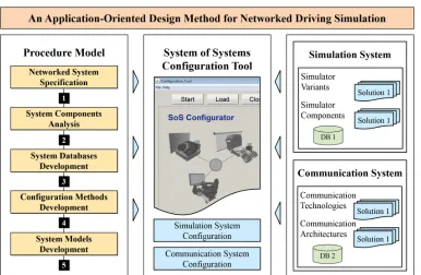
In particular, the concepts of model-based system engineering for building system models are adopted in the design method [14]. The design method consists basically of a procedure model and system of systems (SoS) configuration software as shown in Figure 3. These primary components are described as follows:
• Procedure model
The procedure includes the necessary development phases that are arranged in a specific hierarchy towards the design of multidisciplinary system models for platforms of networked driving simulation. Each development phase contains a set of specific tasks, which shall be carried out in order to obtain the phase objectives. The procedure model specifies the methods and approaches used in each task. Moreover, the procedure model reveals the results of each individual phase. This work is concerned with the comprehensive description of the procedure model and its phases.
• SoS configuration software
The SoS configuration software embeds the methods and approaches of the procedure model to generate application-oriented system models. The SoS configuration software guides non-expert system users in a sequential process to achieve the end objective. Non-expert users can be operators or domain-specific experts. They do not have to acquire deep multidisciplinary knowledge in order to use the SoS configuration software for system model design and generation. A comprehensive description of the design of the SoS configuration software is beyond the scope of this work. The design concepts of an analogous software tool are discussed thoroughly in Reference [18].
the configuration of the constituent simulation systems is carried out in accordance with the requirements of the concerned application scenarios. The second major aspect handles mainly the prioritization process of various network characteristics and functions of available competing communication systems in accordance with the requirements of the concerned application scenarios. Hence, suitable communication systems are selected to guarantee proper system operation and achieve substantial results. The following subsections describe the different phases of the procedure model and their tasks in detail.
4.1. Networked System Specification
The objective of this phase is to provide a clear understanding of the networked driving simulation system by formalizing a holistic system description. Principally, this description combines various aspects of the target system. Available system architecting and description techniques for SoS to date are not sufficient as they typically focus on specific aspects of the SoS [9]. For instance, some architecting techniques concentrate on the synergy of the constituent systems. Others focus on the communication between the constituent systems, with the argument that this particular aspect is common for all SoS types. However, the utilization of a well-established domain-spanning conceptual design method is necessary for the specification of networked driving simulation systems. This assures a broader consideration during its design as a system of systems.
To that end, the CONSENS specification technique is adopted in this phase [19]. The term ‘CONSENS’ is an English acronym that stands for ‘conceptual design specification technique for the engineering of complex systems’. This specification technique mitigates the design complexity by describing the various aspects of the multidisciplinary systems using a set of coherent partial models. In particular, the effective usability of the CONSENS specification technique for the field of conventional driving simulation was validated in Reference [7]. Furthermore, the essential CONSENS partial models in this regard were determined and structured in a specific workflow [7]. Since the CONSENS specification technique is open for the conceptual design of newly emerging complex systems, it undergoes some minor modifications in this work for the development of networked driving simulation. The following subsection discusses the CONSENS workflow adopted in this work.
4.1.1. CONSENS Workflow for Networked Driving Simulation
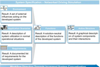
The outcome of the CONSENS specification technique is represented as a principle solution that is described by seven interrelated partial models. Specifically, these partial models are: environment, application scenarios, requirements, functions, active structure, shape, and behavior [20]. Each partial model describes a specific aspect of the target system. To build a coherent system of systems model, the focus is given to the first five partial models in particular. The shape and behavior partial models are not considered in this work as they are more relevant to the development of commercial mechatronic products, such as printers and air conditioners. Figure 4 shows a specified workflow for the five relevant partial models along with their summarized results.
Figure 4. CONSENS workflow for networked driving simulation development.
4.1.2. Identify Environment
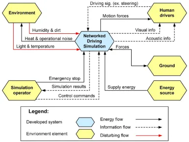
The environment partial model defines all possible external influences that can affect the networked driving simulation system. These external influences can be either environment elements or disturbance variables. Within the environment partial model, the networked driving simulation system is considered as a black box. That is, the internal structure and the constituent systems are not visible in this partial model. In this work, the environment partial model of the networked driving simulation system was determined based on the comprehensive analysis of typical driving simulation facilities as shown in Figure 5. Specifically, the analyses result in the identification of five main environment elements. These are described as follows:
• Drivers
Human drivers represent a crucial environment element. They use the input devices within the driving platforms of the participating driving simulators to control a simulated vehicle in a virtual environment. The main input signals are: acceleration pedal position, brake pedal position, gear selector position, and steering wheel angle. The drivers receive feedback from their driving simulators in the form of motion or vibration, as well as visual and acoustic information. Basically, the motions and vibrations are generated by the eventually utilized motion platforms. In addition, some input devices, such as active steering wheels, can deliver relative motions to the drivers. The visual feedback is represented with virtual scenes displayed to the drivers via the visualization systems. The acoustic feedback is delivered via the acoustic systems as sound effects that accompany the 3D models. The visual and acoustic signals are generated often together by the visualization software.
• Simulation operator
• Energy source
This can be a wall outlet that provides electrical energy to the constituent systems and building components of the networked driving simulation system. Eventually, some components may require power supplies to convert the electrical power of the wall outlet to the levels suitable for their circuitry.
• Ground
This is the physical base of the networked driving simulation system. Dynamic forces occur between the ground and the networked driving simulation system as actions and reactions, especially when the participating driving simulators are equipped with motion platforms. • Environment
The surrounding environment affects the networked driving simulation system through disturbing influences, such as humidity, dirt, light, and temperature. The networked driving simulation system affects the surrounding environment through the produced heat and operation noise.
Figure 5 shows the environment partial model of a networked driving simulation system. The environment elements are illustrated as yellow hexagons, while the networked driving simulation system is represented as a blue hexagon in the center of the model. The interrelations between the networked driving simulation system and the main environment components are categorized mainly as information, energy, and disturbing flows. The information flow denotes the exchange of information between the units of the whole system, such as the measured system variables or environment conditions. The energy flow denotes the transfer of energy between the units of the system, such as mechanical, thermal, or electrical energy. The disturbing flow represents any external factors affecting the normal operation of the system.
Figure 5. Example environment partial model of a networked driving simulation system.
model to systematically determine and mitigate external causes of eventual future malfunctions. The following is an elaboration of the partial model of the application scenarios and its results with respect to networked driving simulation systems.
4.1.3. Define Application Scenarios
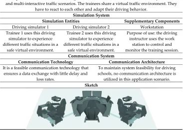
This partial model specifies the potential application scenarios of the networked driving simulation system. Each application scenario describes the target system with respect to the aim of use, operation modes, and the primary constituent systems and building components utilized in this particular application scenario. Specifically, the application scenarios are modeled using the so-called profile pages [19]. Each profile page contains characterizing information about a particular scenario, such as the title, ID, and last modification date. Moreover, each profile page provides a concise description of the application scenario [20]. Eventually, a sketch or a schematic can be added to provide better understanding of the application scenario. As a system of independent and heterogeneous systems, the partial model of the application scenarios of networked driving simulation in this work has a different form than that presented in Reference [19]. Specifically, an overall application scenario is described for the whole networked driving simulation system. This description principally highlights the ultimate goal of the developed system of systems. In addition, a purpose of use is described for each anticipated constituent simulation system. Two or more driving simulators and eventually a traffic simulator can represent a typical set of the constituent simulation systems. Furthermore, a rough description of the essential role of the communication system can be added eventually to the profile page. Table 6 shows the profile page of an example application scenario of a networked driving simulation system that is intended for use in modern driving schools. The example application scenario involves two driving simulators and a workstation for session control and monitoring.
Table 6. Example application scenario of a networked driving simulation system
Application
Scenario 1 Multi-Driver Training in Driving Schools
Status
1 September 2017 Page 1 Description: An instructor at a driving school handles two trainees simultaneously in realistic and multi-interactive traffic scenarios. The trainees share a virtual traffic environment. They
have to react to each other and adapt their driving behavior. Simulation System
Simulation Entities Supplementary Components
Driving simulator 1 Driving simulator 2 Workstation Trainee 1 uses this driving
simulator to experience different traffic situations in a
safe virtual environment.
Trainee 2 uses this driving simulator to experience different traffic situations in a
safe virtual environment.
Purpose of use: the driving instructor uses the work
station to control and monitor the training session. Communication System
Communication Technology Communication Architecture It is a feasible communication technology that
ensures a data exchange with little delay and loss rates.
To maintain system feasibility for driving schools, no communication architecture is utilized in this application scenario. Sketch
the requirements partial model. The following is an elaboration of the requirements partial model and its results with respect to networked driving simulation systems.
4.1.4. Derive Requirements
This partial model specifies a comprehensive list of requirements of the networked driving simulation system. Principally, this list can include functional and non-functional requirements [20]. Moreover, the individual items of requirements can be denoted as demands or wishes (D/W). Table 7 shows an excerpt of an example list of requirements of a networked driving simulation system.
Table 7. Example list of requirements of a networked driving simulation system (excerpt)
ID No. Requirements of Networked Driving Simulation D/W
1
Requirement of Driving Simulator 1
1 Scene simulation system
1.1 It shall cover a 120° horizontal field of view D
… …
2 Motion simulation system
2.1 It shall provide three degrees of freedom W
… …
2
Requirement of Driving Simulator 2
1 Scene simulation system
1.1 It shall cover a 240° horizontal field of view W … …
2 Motion simulation system
2.1 It shall provide five degrees of freedom D
… …
As a system of independent systems, the structure of the list of requirements of networked driving simulation in this work has a different form than the standard form presented in the CONSENS specification technique [19]. Specifically, a separate set of requirements is defined for each independent constituent system and component that is denoted by a unique ID as shown in Table 7. The different sets of requirements together form the overall requirements of the networked driving simulation system. The following is an elaboration of the functions partial model and its results with respect to networked driving simulation systems.
4.1.5. Deduce Functions
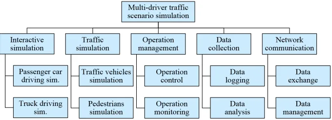
The functions of the networked driving simulation system are defined based on system requirements and application scenarios. Interactive simulation, traffic simulation, operation management, data collection, and network communication are the fundamental system functions identified based on a comprehensive analysis of the networked driving simulation. Each of these defined functions may undergo further top-down hierarchical subdivisions [20]. Figure 6 shows the functions and sub-functions of a networked driving simulation system.
The defined system functions are realized by solution patterns towards system concretization. For instance, the interactive simulation function can be carried out by two or more driving—like passenger car or truck—simulators of different or equal complexity grades. The simulation of traffic vehicles and pedestrians can be performed with an independent traffic simulator. A workstation can provide capabilities of operation control and monitoring. A database console can carry out the data logging function and serve for subsequent simulation session analysis. A communication technology, for instance, such as Ethernet, can carry out the data exchange between the constituent systems and building components. Data management can be achieved by communication architecture, like high-level architecture [21]. As a lot of solutions may be available, a classification scheme (morphological box) can be utilized to facilitate the systematic combination of available solutions [17]. According to the SoS definition adopted in this work, networked driving simulation systems are composed of further heterogeneous constituent systems and building components. Therefore, combining only compatible solutions does not apply in this context in contrast to the design of typical mechatronic systems [17]. The following is an elaboration of the active structure partial model and its results with respect to networked driving simulation systems.
4.1.6. Build Active Structure
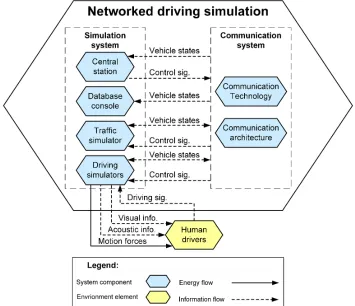
The active structure partial model is created based on the defined system functions and the possible constituent systems and building components of networked driving simulation. In contrast to the environment partial model that considers the whole system as a black box, the active structure partial model concretizes the system by illustrating its internal structure in more detail [20]. Specifically, it shows the main system components and their primary interrelationships in the form of information and energy flows. Figure 7 shows the active structure of a networked driving simulation system including all possible (yet not all necessary) constituent systems and building components. These correspond to the particular system functions defined previously.
The presented active structure partial model includes six constituent systems and building components that belong to two main member groups: simulation system group and communication system group. On the one hand, the driving simulators and the traffic simulator are constituent systems that belong to the simulation system group. Similarly, the workstation and database station are considered as supplementary system components that belong to the simulation system group. On the other hand, the communication technology and the communication architecture belong to the communication system group. To illustrate, Figure 7 depicts the drivers that represent a crucial environment element to illustrate the interaction with the driving simulators that act as central constituent systems of the networked driving simulation system.
In summary, the collective results of the five specified partial models form together a principle solution that acts as a communication and cooperation basis between the experts of the involved development domains [20]. This basis is used for the subsequent design and development phases of the networked driving simulation system in this work. The following subsection presents a comprehensive analysis of system components as a further step towards concretization.
4.2. System Components Analysis
The objective of the second development phase is the identification, description, and classification of the components of the networked driving simulation system. This development phase depends mainly on the results of the system specification phase. Nonetheless, prior to the identification of the system components, a distinction must be clear between the terms ‘constituent systems’ and ‘building components’. On the one hand, the constituent systems are independent participants within the networked driving simulation system. They can carry out meaningful tasks of their own, even if they are not networked to an entire system. On the other hand, the building components can provide services to the system of systems. However, they cannot carry out meaningful tasks of their own, more specifically, when they are not networked to one or more constituent systems. The following is an elaboration of the system components identification task and its results.
4.2.1. Identify System Components
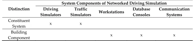
The active structure partial model initially revealed the possible five system components of the networked driving simulation system. These system components can be identified further based on the presented distinction between the constituent systems and building components of the networked driving simulation. On the one hand, the driving and traffic simulators are constituent systems. They can be used separately for useful, independent purposes. On the other hand, workstations, database consoles, and the communication system are building components. They present services to the entire system, but they are not useful if utilized independently without constituent systems. Table 8 presents the five system components and the clear distinction between the constituent systems and the building components.
Table 8. Distinction between constituent systems and building components
Distinction
System Components of Networked Driving Simulation Driving
Simulators
Traffic
Simulators Workstations
Database Consoles
Communication Systems Constituent
System x x
Building
Component x x x
4.2.2. Describe System Components
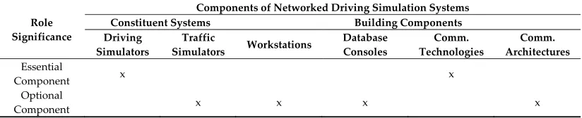
The five main identified system components of the networked driving simulation system can be characterized as essential and optional components based on their roles. Essential system components are vital to achieve the central purpose of networked driving simulation: multi-driver traffic scenario simulation. However, the system of networked driving simulation can operate without the optional components and still achieve this central purpose. The following is a concise description and a role characterization of each system component of the networked driving simulation system from a solution-neutral perspective.
• Driving simulators
They are operated by human drivers to control the respective simulated vehicles. The driving simulators can be of different types, such as a passenger car simulator or a truck simulator. Moreover, driving simulators of different complexity grades can principally participate within the networked driving simulation system. By any means, the participation of at least two driving simulators is necessary not only to achieve the central purpose, but also to establish a system of networked driving simulation. If a third driving simulator is added to the system, one of the driving simulators can be eventually considered as an optional component. However, driving simulators are characterized as essential constituent systems in general.
• Traffic simulators
They generate traffic participants, such as programmed vehicles and pedestrians, to add more complexity to the multi-driver traffic scenario. One traffic simulator is often sufficient for the system of networked driving simulation. However, more than one traffic simulator can be integrated within the system to provide different granularity levels of traffic simulation, such as macroscopic and microscopic traffic flows [22]. The system of networked driving simulation can operate without the utilization of traffic simulators. In this case, the multi-driver traffic scenario simulation depends only on the participating interactive driving simulators. Hence, traffic simulators are characterized as optional constituent systems.
• Workstations
A workstation is utilized to provide control and monitoring operations on the networked driving simulation system. That is, the simulation operator can make commands to stop/start the system and control particular building components. Moreover, the simulation operator can monitor various signals that give indications about the operation and performance of the system and its building components. Principally, the system of networked driving simulation can operate without the use of a workstation. Hence, the workstation is characterized as an optional building component.
• Database consoles
A database console is utilized to capture and save the simulation data. Moreover, operators and developers can conduct simulation analysis or generate after-action-review reports. However, the system of networked driving simulation can operate without the use of a database console. Hence, the database console is characterized as an optional building component.
• Communication systems
Unlike the communication technologies, the system of networked driving simulation can operate without the use of communication architectures. Hence, the communication architectures are characterized as optional building components. Table 9 shows the identified and described system components together with their role significance within the networked driving simulation system.
Table 9. Role significance of constituent systems and building components
Role Significance
Components of Networked Driving Simulation Systems
Constituent Systems Building Components
Driving Simulators
Traffic
Simulators Workstations
Database Consoles
Comm. Technologies
Comm. Architectures
Essential
Component x x
Optional
Component x x x x
The identification and description of system components provided more understanding towards system concretization. Using the results of the identification and description tasks, the following is an elaboration of the components classification task. Main categories of system components are specified as an essential preparation step for the subsequent development phases.
4.2.3. Classify System Components
Based on the functions and active structure established in the previous development phase, system components can be classified into two main groups: the simulation system group and communication system group as shown in Figure 8.
Figure 8. Classification of networked driving simulation system components.
simulators are presented in References [6,7]. The workstations and database consoles can be assigned to the simulation system group. However, these belong to the supplementary components to indicate their relative uncritical role within the system of networked driving simulation. On the other hand, the communication system group includes various communication technologies and communication architectures. This particular classification reflects the functional role of the five main system components within the networked driving simulation as a system of systems. It is used as a basis for the next development phases. The following section presents the development of system databases and the deployment of solution elements.
4.3. System Databases Development
The third development phase depends on the results of the preceding phases and presents another step towards system concretization. The objective of this development phase is to build system databases that contain entries of the analyzed system components, which are concretized as solution elements. While system components are solution-neutral, the solution elements represent concrete products of the system components provided from different developers and manufacturers. In addition, an approach to filling the system databases with entries of the solution elements is presented in this development phase. The system databases are accessible and editable from the system of systems (SoS) configuration software. This is necessary for the subsequent development phases that address the configuration of the networked driving simulation system and the generation of system models. The following is an elaboration of the structure of the system databases.
4.3.1. Build System Databases for Solution Elements
In this task, system databases are developed based on the classification of system components presented in the previous phase. More specifically, two system databases are built for the two main groups of system components: simulation system database and communication system database.
On the one hand, the simulation system database includes only solution elements of components related to the simulation task of the overall system of networked driving simulation. The simulation system database has four tables representing the four component categories that belong to the simulation system group: driving simulators, traffic simulators, workstations, and database consoles. These four database tables are filled with entries of the corresponding solution elements. A database for the solution elements of the individual driving simulator components has been created and filled within Hassan’s method [7]. It has tables for solution elements of three categories of driving simulator components: hardware, software, and resources. This particular database is merged with the simulation system database developed in this work. Its entries can be used eventually during the next phase of system configuration.
On the other hand, the communication system database includes solution elements of components related to the communication task of the overall system of networked driving simulation. The communication system database has two tables representing the two components that belong to the communication system group: communication technologies and communication architectures. Similarly, these two database tables are filled with entries of the corresponding solution elements. Figure 9 depicts the two developed system databases and the main associated tables.
Figure 9. The developed system databases and the main tables.
4.3.2. Fill System Databases with Solution Elements
Apart from the database tables used in Hassan’s methods, six database tables were identified in the previous development task to include solution element entries of six system component categories: driving simulators, traffic simulators, workstations, database consoles, communication technologies, and communication architectures. These database tables must be specified further with attributes before registering entries of corresponding solution elements. The table attributes presented in this development task can be extended arbitrarily so that the design conforms to the open systems approach of the system of systems engineering [9].
23 of 50
Table 10. Database table of driving simulators with building components of specified fidelity levels
ID Name Visualization System Motion System Acoustic System Driver Platform Eye Distance (A) Field of View (B) Rear-View Mirrors (E) Continuity (F) Resolution (G) Motion Standard (L) Motion < 6 DOF (K) Motion > 6 DOF (M) Vehicle Dynamics (N) Tire Model (O) Primary Sound (P) Auxiliary Sound (Q) Sound System (R) Mock-Up (S) HMI (T) Steering (U) Pedals Set (V)
1 ATMOS
simulator 2 3 2 3 2 ‒ 3 ‒ 3 3 1 1 1 4 2 2 1
2 Airmotion
_ride 2 1 3 1 2 1 ‒ ‒ 2 2 1 1 1 1 1 1 1
3 HNI PC
simulator 1 1 3 1 1 ‒ ‒ ‒ 2 2 1 ‒ 1 1 1 1 1
doi:10.20944/preprints201709.0005.v2
Peer-reviewed version available at
Designs 2017 , 1 , 6; doi:10.3390/designs1010006
Peer-reviewed version available at
In addition to the ID and name attributes, this database table has four more attributes in accordance with the four driving simulator components identified in Negele’s guidelines [6]: visualization system, motion system, acoustic system, and driver’s platform. Reference [6] provides a detailed description of these components together with all possible fidelity levels. In accordance with Negele’s guidelines, specific fidelity levels are assigned to the individual components of the driving simulators in this work as shown in Table 10. The subsequent application-oriented configuration and model generation processes will make use of these fidelity level assignments. To conform to the SoS definition adopted in this work, the traffic simulation is considered as a separate task that is independent of the driving simulators in contrast to both Negele’s guidelines and Hassan’s method. The database table of traffic simulator entries mainly has four attributes in addition to the ID: environment database, objects simulation, granularity level, and visualization type. A detailed description of these characteristics is provided in Reference [6]. The third member of the simulation system database is the workstations table. This database table includes solution element entries of workstations that have different capabilities or specifications. The set of attributes can include the ID, name, manufacturer, number of monitors, computer specifications, etc. The fourth member of the simulation system database is the database consoles table. Similarly, this database table includes entries of solution elements of database consoles that have different capabilities or specifications. The set of attributes can include the ID, name, developer, design software, interfaces, storage capacity, and computer specifications. Some of the solution elements of the individual driving simulator components can be characterized based on the features identified in Negele’s guidelines [6]. Specifically, nine driving simulator components were identified in Hassan’s method: visualization system, motion platform, driver’s platform, acoustic system, visualization software, motion controller, vehicle model, HMI interface, and acoustic software. The visualization software, motion platform controller, and HMI interface in Hassan’s method do not have corresponding features in Negele’s guidelines. Hence, the remaining six driving simulator components from Hassan’s method are correlated to features from Negele’s guidelines. This correlation step represents the link established in this work between Hassan’s method and Negele’s guidelines. The database tables of the individual driving simulator components are extended in this work to allow for the fidelity level assignments of the solution elements. With respect to the communication system, a database table includes entries of all available communication technologies as solution elements. These communication technologies differ mainly through network characteristics. In addition to the ID and name attributes, this database table has one main attribute representing significant characteristics of the communication technologies [26]. For instance, this attribute is divided into eight sub-attributes: bandwidth, latency, jitter, packet loss rate, determinism, error rate, transmission mode, and segment length. Another database table includes entries of all available communication architectures as solution elements. These communication architectures differ mainly through the provided functions and services for networked simulation. In addition to the ID and name attributes, this database table has one main attribute representing significant characteristics, functions, and services of the communication architectures. Further attributes can be added to the database table of communication architectures, such as the provider and the version of the underlying standard. The following subsection presents a central development phase of the design method.
4.4. Configuration Methods Development
Table 11. Morphological box of the networked driving simulation system (excerpt)
System Components
Solution Elements
1 2 3
Driving Simulators
Traffic Simulators
Workstations
Database Consoles
Communication Technologies
Communication Architectures
In general, the morphological box represents a well-established approach that can be used particularly when it comes to system composition [17]. In this work, the system components and the corresponding available solution elements are inserted into the rows of a morphological matrix as shown in Table 11. While the first four system components belong to the simulation aspect of the networked driving simulation system, the latter two system components belong to the communication aspect. The solution elements of system components must be combined systematically to obtain an overall solution. The networked driving simulation system is composed of independent, heterogeneous systems. Hence, the combination of solution elements is not governed by their consistency or compatibility in this work in contrast to Hassan’s method [7]. The solution elements are selected based on the offered capabilities and functionalities with respect to the requirements of the concerned application scenarios. The following is a discussion of a configuration method for the simulation aspect of the networked driving simulation system.
4.4.1. Simulation System Configuration Method
Selection Approach for Available Driving Simulators
Classifying driving simulators into three categories (low-level, mid-level, and high-level) collectively is not practical [13]. A driving simulator may have high capability for one particular component and low capability for other components based on the purpose of use [14]. Hence, driving simulators are classified in this work in accordance with the 15 application classes defined in Negele’s guidelines [6]. These application classes give more insight into the fidelity levels of the individual driving simulator components. While seven application classes are considered as not common or practical, eight application classes are fully specified in Negele’s guidelines [6]. Nonetheless, the specifications of available driving simulators may not exactly fulfill the whole requirements of the application classes. Therefore, a cost function is defined to give a quantified indication of the specification/requirement deviations.
The relative significances of the individual driving simulator components are specified for each application class in Negele’s guidelines [6]. For instance, the motion system is more significant than the visualization system for the application class 1a (skill-based responses and vehicle stabilization). In this work, the relative significance is quantified, where each driving simulator component takes a unique integer number from 1 to 4. Higher numbers mean more relative significances. With respect to the application class 1a for example, the significance numbers: 4, 3, 1, and 2 are assigned to the simulator components: motion system, visualization system, acoustic system, and driver’s platform respectively. Based on the specified and quantified relative significances, Equation (1) presents the cost function developed in this work to give an indicative measure of the deviation between the specifications of the available driving simulators and the requirements of the application classes:
Fidelity level deviation = SignificanceN × |Level ( ) − Level ( )|
, (1)
where:
m Designation of the driving simulator component
Significancem Specified relative significance value of a simulator component
n Designation of the feature of a driving simulator component N Maximum number of features of a driving simulator component LevelReq Requirement feature fidelity level of a simulator component
LevelSpec Specification feature fidelity level of a simulator component
This cost function is applied to each available driving simulator with respect to each application class. The minimal deviation value among all available driving simulators with respect to a particular application class indicates a best possible match between the specifications and the requirements. With respect to any particular application class, Equation (2) presents a simple function used to find the minimal deviation value among all driving simulators.
Best matching simulator = Min (Deviation , Deviation , Deviation , … , Deviation ), (2)
where n is the number of available driving simulators. The resulting minimal deviation value is used to select the driving simulator, whose specifications best match the requirements of a concerned application class. Further cost functions can be eventually developed, provided that they can give unique selections of driving simulators. The developed cost function has been applied to the three exemplary driving simulators of Table 10 and showed very good results, where no ambiguous selections were provided. Error! Not a valid bookmark self-reference.Table 12 shows these results with respect to the eight specified application classes.
Table 12. Results of the developed cost function for three example driving simulators
Example Driving Simulators
Specified Driving Simulator Application Classes
ATMOS
driving simulator 2.04 2.15 3.22 3.22 2.00 1.81 2.00 2.00
Airmotion_ride
driving simulator 3.26 2.23 1.48 1.48 1.38 2.38 1.80 1.80
HNI PC-based
driving simulator 3.15 2.30 1.30 1.30 1.96 2.96 1.78 1.78
Example minimal deviation values are highlighted in Table 12 supposing that the database table contains entries of only three driving simulators. For instance, the HNI PC-based driving simulator can be used for the application class 3b (navigation driving tasks with rule-based responses) and the application class 3c (navigation driving tasks with knowledge-based responses). The Airmotion_ride driving simulator can be used for the application class 4b that addresses secondary driving tasks with rule-based responses [6]. The ATMOS driving simulator can serve the application class 4c that addresses secondary driving tasks with knowledge-based responses [6]. If other entries of driving simulators are added to the database table and the cost function is applied, the results of the minimal deviation function will differ with respect to each application class.
Selection Approach for Further Available Simulation System Components
The selection of solution elements of traffic simulators, workstations, and database consoles is more convenient and straightforward due to the limited number of characterizing features. A similar approach can be applied to these simulation system components, however, without the use of a particular predetermined significance factor. That is, the deviation between the specifications of the available solution elements and the requirements of the application scenarios can be determined through any simple cost functions based on comparison tables.
Selection Approach for Available Driving Simulator Components
The available driving simulators may not be satisfactory if the deviations between their specifications and the requirements of the concerned application classes are large. In such cases, new driving simulators can be built through combining solution elements of the different driving simulator components. Hassan’s method can be utilized for this particular purpose [7]. In this regard, the previous development phase presented an approach to assign feature fidelity levels from Negele’s guidelines to the solution elements of the driving simulator components specified in Hassan’s method. Moreover, the associated database table has been modified to include these assignments. According to Negele’s guidelines, driving simulator components are characterized by a set of features. For instance, the visualization system is characterized by five features: eye distance, field of view, rear-view mirrors, continuity, and resolution.
Nonetheless, the features of an available solution element, together, may not have the exact fidelity levels that fulfill the corresponding requirements of a particular application class. Therefore, a cost function must be defined to give a quantified indication of the deviation. No relative significances for the features of the individual driving simulator components are specified in Negele’s guidelines. Hence, no particular significance factor is used within the cost function. Equation (3) presents the cost function developed in this work to give an indicative measure of the deviation between the specifications of individual driving simulator components and the corresponding requirements of the application classes:
Fidelity level deviation = Level ( ) − Level ( ) , (3)
where:
n Designation of the feature of a driving simulator component N Maximum number of features of a driving simulator component LevelReq Requirement feature fidelity level of a simulator component
This cost function is applied to all available solution elements of each driving simulator component with respect to the corresponding requirements of each application class. Among all solution elements of a particular driving simulator component, the minimal deviation value indicates a best possible specifications match to the corresponding requirements of the concerned application class. With respect to any particular driving simulator component and an application class, Equation (4) presents a simple function used to find the minimal deviation value among all solution elements. Best matching component = Min(Deviation , Deviation , Deviation , … , Deviation ), (4)
where n is the number of available solution elements of any particular driving simulator component. This approach complements the process of driving simulator configuration introduced in Hassan’s method [7]. Specifically, the selection of solution elements of driving simulator components is governed by their capability to fulfill the corresponding requirements of the concerned application scenarios. The following is a discussion of a configuration method for the communication aspect of the networked driving simulation system.
4.4.2. Communication System Configuration Method
The communication system aspect in this work includes two system components: communication technologies and communication architectures. While using a communication technology is essential for the operation of the networked driving simulation system, the communication architectures are classified as optional building components. There are a lot of solution elements for both building components from different providers. Moreover, the available solution elements are usually subjected to continuous development to establish variants of different characteristics and functions. A careful selection of the communication system is necessary to reach the expected outcomes of the networked driving simulation system.
Determining Priority of Communication Characteristics and Functions
Communication technologies are characterized typically by a set of network characteristics, such as bandwidth and latency. However, no particular communication technology can provide the best possible specifications regarding all network characteristics [27]. Therefore, it may be difficult to find an absolute optimal solution element for all application scenarios due to the presence of various conflicting network characteristics and myriad choices of available communication technologies. This leads to a typical multi-criteria decision-making problem [28]. Thereby, the network characteristics represent the criteria and the communication technologies represent the alternatives. In general, there are different methods in the literature to handle multi-criteria decision making problems [28]. Nonetheless, some of these methods require a prior assignment of priority weights to the different criteria. This is necessary to ultimately reach a compromised solution. The compromised solution in this regard refers to a choice that satisfies the most important criteria to a sufficient extent while partially satisfying the less important criteria.
29 of 50
Table 13. Priority analysis matrix including example network characteristics
Priority Scheme 1 = Equally Important
5 = More Important 10 = Much More Important
0.2 = Less Important 0.1 = Much Less Important
Network Characteristics
Sum of Weights Priority Weight (%) Bandwidth Packet Loss Rate Determinism Latency Segment Length
Bandwidth x 5 0.2 1 10 16.2 29.35
Packet loss rate 0.2 x 0.2 1 5 6.4 11.59
Determinism 5 5 x 5 10 25 45.29
Latency 1 1 0.2 x 5 7.2 13.04
Segment length 0.1 0.2 0.1 0.2 x 0.4 0.730
doi:10.20944/preprints201709.0005.v2
Peer-reviewed version available at
Designs
2017
,
1
, 6;
doi:10.3390/designs1010006
Peer-reviewed version available at
Designs
2017
,
1
, 6;
Table 13 for a set of five network characteristics. For instance, the bandwidth can be less important than the determinism, but much more important than the segment length for a particular application scenario. The overall relative priority weight of each network characteristic is calculated as a sum of weights. The final priority weighting percentages of each network characteristic are calculated according to Equation (5).
Priority weighting (%) = (Sum of weights × 100) / Sum of weights , (5)
where:
n and m Designations of the network characteristics n and m M Total number of network characteristics
The priority weighting percentages reflect the unique significances of the individual network characteristics with respect to a concerned application scenario. Although the shown example priority analysis matrix includes only five network characteristics, it can be extended vertically and horizontally to include more network characteristics as desired.
Similarly, the communication architectures are characterized typically by a set of functions for networked simulation. However, no particular communication architecture can provide the best possible specifications regarding all functions. Hence, the communication functions must be prioritized with respect to the application scenarios to reach a compromised solution. A similar approach can be used to assign priority weights to the functions of the communication architectures based on the requirements of the concerned application scenarios.
Selection Approach for Available Communication Systems
After determining the relative priorities of the communication characteristics and functions, a decision-making method is required to avoid an exhaustive and impractical search among all available solution elements of the communication technologies and communication architectures. The cost–benefit analysis method is used in this work as a well-established decision-making process recognized by systems engineering [29]. Based on this method, Table 14 shows an exemplary assessment of three communication technologies with respect to five network characteristics.
Table 14. Example assessment according to the cost-benefit analysis method
Network Characteristics Priority Weight (%) Communication Technologies
Ethernet 10 Mbps CAN Bus InfiniBand
Fulfillment (%) Partial Assessment (%) Fulfillment (%) Partial Assessment (%) Fulfillment (%) Partial Assessment (%)
Bandwidth 29.35 80 23.5 20 5.87 100 29.4
Packet loss rate 11.59 10 1.16 100 11.6 100 11.6
Determinism 45.29 00 0.00 100 45.3 00 0.00
Latency 13.04 00 0.00 100 13.0 00 0.00
Segment length 0.730 100 0.73 50 0.37 30 0.22
Final assessment (%) 25.39 76.14 41.22
![Table 3. Morphological box for driving simulator components (excerpt) [7]](https://thumb-us.123doks.com/thumbv2/123dok_us/7938347.1317943/8.612.132.483.83.470/table-morphological-box-driving-simulator-components-excerpt.webp)
![Table 5. Consistency matrix of driving simulator solution elements (excerpt) [7]](https://thumb-us.123doks.com/thumbv2/123dok_us/7938347.1317943/10.612.102.515.186.342/table-consistency-matrix-driving-simulator-solution-elements-excerpt.webp)