829
©IJRASET: All Rights are Reserved
Experimental Study on the Effects of Process
Parameters on MRR in Incoloy 825 using
Wire EDM Process
Muhammed Shiyas1, Rahul M2, Muhammed Kareem3, Shyam Krishnan P R4, N N Raeez Mohammed5
1, 2, 3, 4, 5
Mechanical Engineering Department, Adi Shankara Institute of Engineering and Technology, Kalady, Kerala. PIN-683574
Abstract: Incoloy 853 is the latest version of super alloy in Incoloy series with improved corrosion resistance, mechanical properties and weldability. So, it is preferred for wide range of application like chemical processing, oil and gas, nuclear fuel reprocessing, acid production, pulp and paper production industry etc. This project deals with the experimental study on the effects of various process parameters of WEDM like pulse on time (TON), pulse off time (TOFF), peak current (IP) and wire feed (WF) have been investigated to reveal their impact on material removal rate on Incoloy 825. The regression equation of Material Removal Rate is also finding out by using MiniTab’18 software so that the variation of predicted MRR can be analysed. Keyword s: Incoloy 825, WEDM, Material Removal Rate, Regression equation, Pulse ON/OFF time, Peak current, Wire Feed
I. INTRODUCTION
[image:1.612.200.420.530.696.2]Wire Electrical discharge machining (WEDM) is a non-traditional, thermoelectric process which wear away material from the work piece by a series of discrete sparks between a work and tool electrode submerged in a liquid dielectric fluid (Soft water (D.M Water) + Gel). These electrical discharges melt and vaporize minute amounts of the work material, which are then ejected and flushed away by the dielectric. The schematic representation of the WEDM cutting process is shown in Figure 1. Wire electrical discharge machining (WEDM) is a specialized thermal machining process capable of accurately machining parts with varying hardness or complex shapes [3]. At present, WEDM is a wide spread technique used in industry for high-precision machining of all types of conductive materials such as metals, metallic alloys, graphite, or even some ceramic materials, of any hardness. As newer and more exotic materials are developed, and more complex shapes are presented, conventional machining operations will continue to reach their limitations and the increased use of wire EDM in manufacturing will continue to grow at an accelerated rate. As an alloying element, Cr has very significant effects on the metallurgical aspect of the martensite stainless steels. Cr and C are specifically added to steel to ensure the formation of the super alloys (INCOLOY 825) after the hardening. Ni can be added, and it enhances both the yield strength and ductility of these alloys. The present study highlights the effects of various process parameters of WEDM like pulse on time (P ON), pulse off time (P OFF), peak current (IP) and wire feed (WF) have been investigated to reveal their impact on material removal rate on Incoloy 825 using one variable at a time approach.
830
©IJRASET: All Rights are Reserved
II. LITERATUREREVIEW
“Nickel, Cobalt, and Their Alloys” edited by Joseph R. Davis [1], ASM Speciality hand book (2000) This hand book gives the Chemical composition, Mechanical Properties, Physical properties, Chemical properties specification, and Applications of INCOLOY 825. This hand book also gives the corrosion rate of these alloys. “Non-conventional Machining Version 2- Electro Discharge Machining; Lesson39” an online book from Mechanical Engineering Dept., IIT Kharagpur. This book gives the working and Parameters influencing the Wire EDM. “Effects of process parameters on material removal rate in WEDM” H. Singh, R. Garg Mechanical Engineering Department, National Institute of Technology, Kurukshetra, India Received 06.11.2008; published in revised form 01.01.2009. This paper presents the effects of various process parameters of WEDM to reveal their impact on material removal rate of hot die steel (H-11) using one variable at a time approach. Material Data sheet of VDM alloys of Incoloy 825 are also studied. All its property, chemical composition etc., are obtained from this material data sheet. International Journal of Mechanical And Production Engineering, ISSN: 2320-2092, Volume- 4, Issue-7, Jul.-2016Optimization of Surface Roughness and Material Removal Rate in Turning of AISI D2 OPTIMIZATION OF SURFACE ROUGHNESS AND MATERIALREMOVAL RATE IN TURNING OF AISI D2 by R.A. Muley, A.R.K Ulkarni and R.R. Deshmukh, Mechanical Engineering Department, JNEC, Aurangabad. This journal presents the optimization of material removal rate (MRR) and surface roughness for a given range of cutting parameters in turning operation on AISI D2 steel.
III.PROBLEMIDENTIFICATION
In conventional machining technique the properties of the work material may get changed due to increase in temperature due to this reason non-conventional machining techniques such as WEDM is used for maintaining the properties. In non-conventional machining there is no direct contact between the tool and the work piece, energy is utilized in its direct form (thermal, mechanical, electrical…). Incoloy 825 is a new super alloy in the Incoloy series. It has very good properties such as high corrosion resistance, impact strength, tensile strength etc. The only limitation of this alloy is its lack of machinability. If conventional machining techniques are used on this material, it will damage the crystal structure due to the rise in temperature this will lead to the change of properties of the material. So for machining materials without losing its properties non-conventional technique such as Wire cut EDM is preferred.
IV.EXPERIMENTALPROCEDURE
A. Material: Incoloy 825
INCOLOY 825 which is favoured in many Industry field is taken for this experimental investigation. It is a Ni-Fe-Cr alloy with addition of Cu, Mo, Ti which is high resistance to aqueous corrosion. It has high nickel content, sufficient to resist chloride ion stress corrosion cracking, and a very stable austenite structure. The levels of Mo and Cu enable the alloy to resist reducing agents and acids. Chromium gives resistance to oxidising conditions, such as nitric acid solutions, nitrates and oxidising salts. The alloy is titanium stabilised to resist pitting and intergranular attack after fabrication, particularly welding, which includes heating in the critical sensitisation temperature ranges from 650°C – 760°C. It is mainly used for chemical processing, oil and gas well piping, nuclear fuel reprocessing, acid production, pickling equipment propeller shafts, tank trucks and so on[1,2].
TABLEI
Chemical Composition % of Incoloy 825
Grade Ni% Cr% Mo% Fe% Al% Ti% C% Mn% Si% Cu% P% S%
Incoloy
825 38-46
19.5-23.5 2.5-3.5 Bal. Max 0.2 0.6-1.2
Max 0.05
Max 1.0
Max
0.5 1.5-3.0
Max 0.02
Max 0.03
TABLEII
Mechanical Properties % of Incoloy 825
Heat Treatment Tensile Strength Yield Strength
σp0.2/ MPa
Elongationσ
σ5 /% Brinell Hardness
831
©IJRASET: All Rights are Reserved
TABLEIII
Physical Properties % OF Incoloy 825
Grade Density Melting Point
Incoloy 825 8.1g/cm³ 1370ºC- 1400ºC
B. Equipment: Wire Cut EDM
Wire Electrical discharge machining (WEDM) is a non-traditional, thermoelectric process which erodes material from the work piece by a series of discrete sparks between a work and tool electrode immersed in a liquid dielectric medium. These electrical discharges melt and vaporize minute amounts of the work material, which are then ejected and flushed away by the dielectric. The schematic representation of the WEDM cutting process is shown in Figure 1.Wire electrical discharge machining (WEDM) is a specialized thermal machining process capable of accurately machining parts with varying hardness or complex shapes, which have sharp edges that are very difficult to be machined by the main stream machining processes. At present, WEDM is a common technique used in industries for high-precision machining of all types of conductive materials such as metals, metallic alloys, graphite, or even some ceramic materials, of any hardness [3-5].
Many Wire-EDM machines have adopted the pulse generating circuit using low power for ignition and high power for machining. However, it is not suitable for finishing process since the energy generated by the high-voltage sub-circuit is too high to obtain a desired fine surface, no matter how short the pulse-on time is assigned [6].As newer and more exotic materials are developed, and more complex shapes are presented, conventional machining operations will continue to reach their limitations and the increased use of wire EDM in manufacturing will continue to grow at an accelerated rate [7].
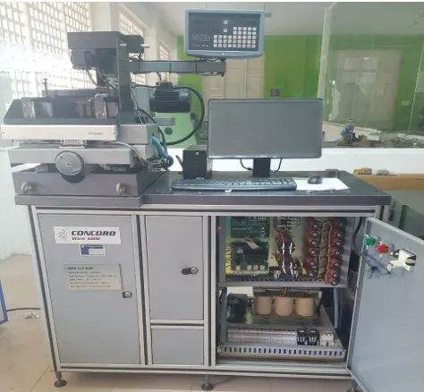
Fig. 2 CONCORD Wire EDM cutting machine
C. Experimental Methodology
The experimental studies were performed on CONCORD wire EDM, model no: DK-7712 with a CNC control system (Figure 2). For the dielectric fluid a mixture of soft water (D.M water) and silica gel is used. Various input parameters varied during the experimentation are pulse on time (P ON), pulse off time (P OFF), peak current (IP) and wire feed rate (WF). The effects of these input parameters are studied on material removal rate using one factor at a time approach. The units of some input parameters such as pulse on time, pulse off time, wire feed etc. are taken as per the machine setting [8, 9].
[image:3.612.193.430.335.554.2]832
©IJRASET: All Rights are Reserved
2 mm thickness and 40 mm length was used. During the experiments 2mm × 40mm was cut to obtain a rectangular punch of 2 mm × 40 mm × 1 mm. To evaluate the effects of machining parameters on performance characteristic (MRR), and to identify the performance characteristic under these machining parameters, a specially designed experimental procedure is required.
TABLEIV Experimental Parameters
V. OBSERVATION
Various experiments were performed to find how the output parameter varies with the variation in the input parameters. The experiments were performed in constant voltage mode of the WEDM. In the first set of experiments peak current (IP) is varied from 1 amp to 3 amp in the decrements of 1 amp. All other input parameters such as wire feed, wire tension, servo voltage, pulse on time, and pulse off time are fixed to some value. The change in material removal rate due to change in pulse on time is shown in Table V. Fixed input variables in first set of experiments are:
P ON= 40sec ; P OFF= 9sec; WF = 190mm/s
TABLEV
EXPERIMENTAL PARAMETERS WITH VARYING IP
SI No. Peak Current (A)
Pulse ON Time (s)
Pulse OFF Time (s)
Wire feed (mm/s)
Time (s)
MRR (mmᵌ/s)
1 1 40 9 190 300.93 0.04785165985
2 2 40 9 190 301.86 0.04770423375
3 3 40 9 190 300.00 0.048
In the second set of experiments pulse on time (P ON) is varied from 40sec to 50sec in the steps of 5sec. All other input parameters such as wire feed, wire tension, servo voltage, peak current, pulse off time were kept constant. The change in material removal rate due to change in pulse on time is shown in Table VI.
Fixed input variables in second set of experiments are: P OFF=11sec; IP = 2 A; WF = 200mm/s
TABLEVI
Experimental Parameters with varying P ON SI No. Pulse ON
Time (s)
Peak Current (A)
Pulse OFF Time (s)
Wire feed (mm/s) Time (s) MRR (mm³/s)
1 40 2 11 200 284.61 0.05059555181
2 45 2 11 200 284.40 0.05063291139
3 50 2 11 200 288.00 0.05
SI No. Peak
Current (A) Pulse ON Time (s) Pulse OFF Time (s)
Wire feed (mm/s)
1 1 40 9 190
2 1 45 13 190
3 1 45 13 200
4 1 45 13 210
5 2 40 9 190
6 2 40 11 200
7 2 45 11 200
8 2 50 11 200
9 3 40 9 190
10 3 50 9 210
11 3 50 11 210
833
©IJRASET: All Rights are Reserved
In the third set of experiments pulse off time (P OFF) is varied from 9sec to 13sec with regular increment of 2sec. All other input parameters such as wire feed, wire tension, servo voltage, peak current, pulse on time are fixed to some constant value. The change in material removal rate due to change in pulse on time is shown in Table VII.
Fixed input variables in third set of experiments are: P ON= 50 sec; IP = 3 A; WF = 210 mm/s
TABLEVII
Experimental Parameters with varying P OFF
SI No. Pulse OFF Time(s)
Peak Current (A)
Pulse ON Time(s)
Wire feed (mm/s) Time (s) MRR (mm³/s)
1 9 3 50 210 272.18 0.05290616504
2 11 3 50 210 271.08 0.05312084993
3 13 3 50 210 286.42 0.05027581873
In the next set of experiments wire feed (WF) is varied from190mm/s to 210mm/s in the steps of 10mm/s. All other input parameters such as pulse on time, pulse off time wire tension, servo voltage, peak current time are fixed to some value. The change in material removal rate due to the change in pulse on time is shown in Table VIII.
Fixed input variables in fourth set of experiments are: P ON = 45sec; P OFF = 13sec; IP =1 Amp;
TABLEVIII
Experimental Parameters with varying P OFF
SI No. Wire feed (mm/s)
Peak Current (A)
Pulse ON Time (s)
Pulse OFF Time (s)
Time (s)
MRR (mm³/s)
1 190 1 45 13 302.40 0.04761904762
2 200 1 45 13 295.37 0.04875241223
3 210 1 45 13 284.59 0.05059910749
VI.RESULTANDANALYSIS
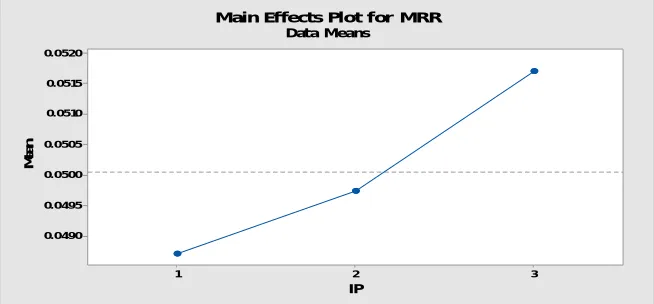
The experiments are based on one factor experiment strategy. In this only one input parameter was varied while keeping all others input parameters at constant values. During this experimental procedure, four sets of experiments were performed. After analysing the results of the experiments performed, various facts came into light. The effect of peak current (IP) on the output parameter is shown in Figure 3. The graph shows that material removal rate increases with the increase in the peak current ie. maximum the peak current results in maximum Material Removal Rate. So the peak current can be adjusted to get the desired material removal rate.
3 2 1 0.0520 0.0515 0.0510 0.0505 0.0500 0.0495 0.0490 IP M e a n
Main Effects Plot for MRR
[image:5.612.83.530.176.248.2]Data Means
[image:5.612.84.532.369.445.2] [image:5.612.142.469.559.711.2]834
©IJRASET: All Rights are Reserved
For the next set of experiment P ON is varied. The effect of pulse on time (P ON) on the output parameter ie. The Material Removal Rate is shown in Figure 4.The graph shows that material removal rate increases with the increase in the pulse on time. Pulse ON can be increased to get the maximum Material Removal Rate. So the pulse on time can be adjusted to get the desired material removal rate.
50 45
40 0.0515
0.0510
0.0505
0.0500
0.0495
0.0490
0.0485
P ON
M
e
a
n
Main Effects Plot for MRR
[image:6.612.127.488.134.369.2]Data Means
Fig. 4 Pulse ON v/s Material Removal Rate
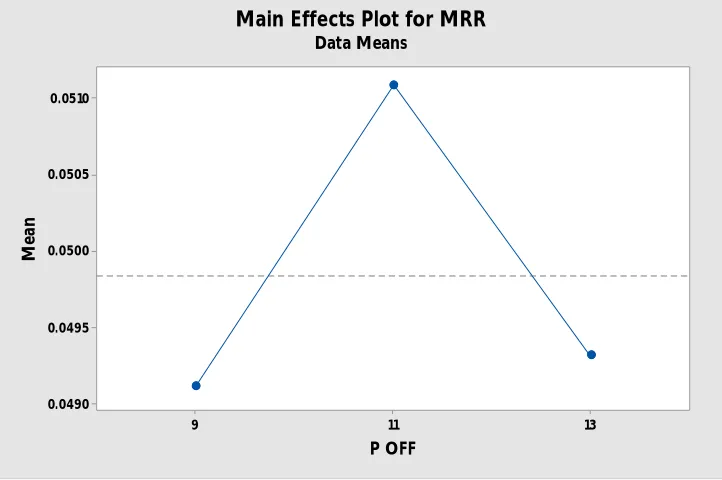
For the third set of experiments the effect of pulse off time (P OFF) on the output parameter is shown in the figure 5. And from the graph it results that firstly the Material Removal Rate and then it decreases with the pulse OFF time.
13 11
9 0.0510
0.0505
0.0500
0.0495
0.0490
P OFF
M
e
a
n
Main Effects Plot for MRR
Data Means
Fig. 5 Pulse OFF v/s Material Removal Rate
[image:6.612.130.491.420.660.2]835
©IJRASET: All Rights are Reserved
210 200
190 0.052
0.051
0.050
0.049
0.048
W F
M
e
a
n
Main Effects Plot for MRR
[image:7.612.130.493.75.312.2]Data Means
Fig. 6 Wire Feed v/s Material Removal Rate
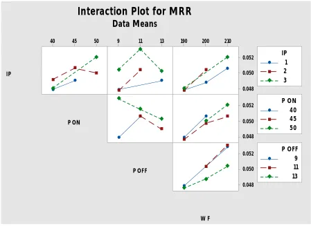
The interaction plot for MRR is shown in figure 7
50 45
40 9 11 13 190 200 210
0.052
0.050
0.048
0.052
0.050
0.048
0.052
0.050
0.048 IP
P ON
P OFF
W F
1 2 3 IP
40 45 50 P ON
9 11 13 P OFF
Interaction Plot for MRR
Data Means
Fig. 7 Interaction Plot for MRR
[image:7.612.86.535.360.687.2]836
©IJRASET: All Rights are Reserved
parameter design of performance characteristics, for the purpose of designing and improving the quality of the product [10]. Regression analysis can be used for prediction and forecasting of Material Removal Rate using the experimental datas.
A. Design Of Experiment Based On Taguchi Method
To evaluate the effects of cutting parameters of wire EDM process in terms of cutting performance characteristics such as surface roughness a Taguchi method used here to model the wire EDM process. In this study, Taguchi method, a powerful tool for parameter design of performance characteristics, for the purpose of designing and improving the product quality [10]. A collection of data is accomplished after cutting the Incoloy 825 material by wire EDM. cutting time has been observed and noted after each experiment and material removal rate (MRR) have been calculated by applying formula shown in equation (1). These collected data have been analysed by using powerful statistical software Minitab 16. In this software, Taguchi method has been considered for analysis of collected values of response parameters.
MRR= (mm3/sec) (1)
Where, l = cutting length (mm), h = cutting thickness (mm), k = kerf of cutting (mm), = machining time (sec).
Dring statistical analysis and ANOVA analysis, larger is better concept is used for deciding the significant input parameters during analysis of MRR. Smaller is better criterion is considered for deciding the significant input parameters during analysis of surface roughness (Ra) [11]. Regression Analysis is regarded as a powerful tool for representing the relationship between input parameters and the process responses [12].
TABLEIIX Analysis of variance
Source DF Adj SS Adj MS F-Value P-Value
Regression 4 0.000035 0.000009 11.79 0.003
IP 1 0.000000 0.000000 0.01 0.912
P ON 1 0.000000 0.000000 0.26 0.625
P OFF 1 0.000002 0.000002 2.95 0.130
W F 1 0.000013 0.000013 17.30 0.004
Error 7 0.000005 0.000001
Total 11 0.000040
TABLEXCoefficients
Term Coef SE Coef T-Value P-Value VIF
Constant 0.01081 0.00699 1.55 0.166
IP 0.000049 0.000432 0.11 0.912 2.01
P ON 0.000050 0.000098 0.51 0.625 2.59
P OFF -0.000371 0.000216 -1.72 0.130 2.01
837
©IJRASET: All Rights are Reserved
B. Regression Equation
Equation represents the prediction models for Material Removal Rate:
MRR = 0.01081 + 0.000049 IP + 0.000050 P ON - 0.000371 P OFF + 0.000204 W F
C. Experimental MRR v/s Predicted MRR
TABLEXIII
Resultant table with predicted MRR and its error
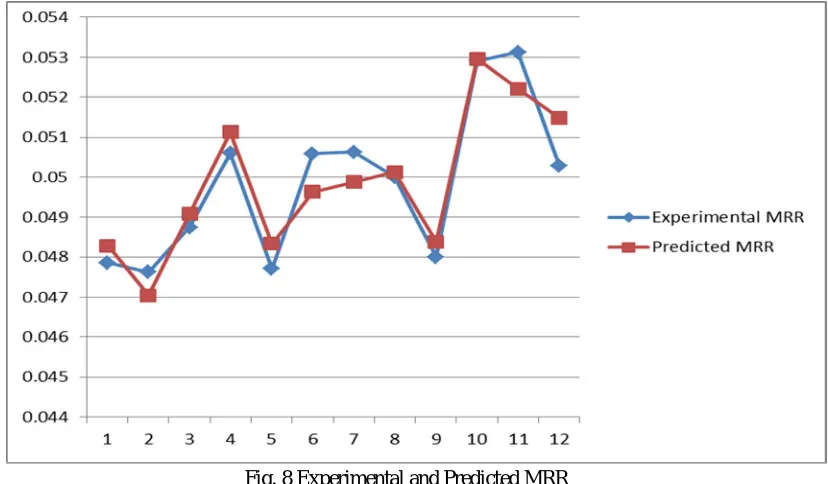
[image:9.612.60.553.191.421.2]The plot between the predicted MRR and experimental MRR is shown in figure 8. The difference between the two plots gives its error.
Fig. 8 Experimental and Predicted MRR
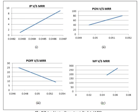
The plot between the predicted MRR and the varying parameters is shown in figure 9. That is the plot of SI
No.
Peak Current
(A)
Pulse ON Time
(s)
Pulse OFF Time
(s)
Wire feed (mm/s)
MRR (mm³/s)
Error Experimental
Predicted (Using Regression
equation)
1 1 40 9 190 0.04785165985 0.04828 -0.00042834 2 1 45 13 190 0.04761904762 0.047046 0.000573048 3 1 45 13 200 0.04875241223 0.049086 -0.000333588 4 1 45 13 210 0.05059910749 0.051126 -0.000526893 5 2 40 9 190 0.04770423375 0.048329 -0.000624766 6 2 40 11 200 0.05059555181 0.049627 0.000968552 7 2 45 11 200 0.05063291139 0.049877 0.000755911
8 2 50 11 200 0.05 0.050127 -0.000127
9 3 40 9 190 0.048 0.048378 -0.000378
[image:9.612.103.517.458.700.2]838
©IJRASET: All Rights are Reserved
Fig. 9 Plot on Varying Parameter v/s Predicted MRR
VII. CONCLUSION
The significance of input variables peak current, pulse on time, pulse off time and wire feed rate of Wire EDM on Material removal rate of Inconel 825 super alloy has been studied. Regression techniques have been adopted using MiniTab'18 software to find the deviation between predicted MRR and experimental MRR. From the experiment the maximum MRR is obtained with parameters of 3 A current, 50 s pulses on time, 11 s pulse off time and 210 mm/s wire feed. And minimum MRR is obtained with parameters of 1 A current, 45 s pulse on time, 13 s pulse off time and 190 mm/s wire feed. This infers that the material removal rate increases with the increase in Peak current and decrease in Wire feed rate. MRR also increases with the increase in Pulse ON time. In the case of pulse off time the experimental MRR, firstly increases and then decreases and predicted MRR is a decreasing slope. And so the MRR and P OFF are inversely proportional. A linear regression equation has been obtained for the material removal rate
MRR = 0.01081 + 0.000049 IP + 0.000050 P ON - 0.000371 P OFF + 0.000204 W F
There is a slight deviation between the predicted MRR and experimental MRR, this deviation represents the accuracy of regression equation.
VIII.ACKNOWLEDGMENT
It is with immense pleasure and satisfaction that we bring out this project report. We feel obliged to acknowledge the support and guidance that came from the various quarters during the course of the completion of the project.
We would like to express our deep sense of gratitude to our college and staffs for the continuous support, providing the facilities and for the technical support.
[image:10.612.87.529.76.433.2]839
©IJRASET: All Rights are Reserved
Finally, above all we owe our gratitude to the almighty for showering abundant blessings. Last but not the least we express our gratitude to our parents and friends for their continuous, moral and material support throughout the course and in helping us to finalize the presentation.
REFERENCES
[1] Data sheet of Incoloy 825 [Online} Available http://www.niwire.com/product/corrosion-resistant-alloy/incoloy-825/ 2015 NiWire Industries Co., Ltd. [2] “Nickel, Cobalt, and Their Alloys” edited by Joseph R. Davis, ASM Speciality hand book (2000). A hand book on Incoloy 825.
[3] K.H. Ho, S.T. Newman, S. Rahimifard, R.D. Allen, State of the art in wire electrical discharge machining (WEDM), International Journal of Machine Tools and Manufacture 44 (2004) 1247-1259.
[4] A. Gatto, L. Luliano, Cutting mechanisms and surface features of WEDM metal matrix composite, Journal of Material Processing Technology 65 (1997) 209-214.
[5] I. Puertas, C.J. Luis, A study on the machining parameters optimization of electrical discharge machining, Journal of Materials Processing Technology 143-144 (2003) 521- 526.
[6] Y.S. Liao, J.T. Huang, Y.H. Chen, A study to achieve a fine surface finish in Wire-EDM, Journal of Materials Processing Technology 149 (2004) 165-171. [7] T.A. Spedding, Z.Q. Wang, Study on modeling of wire EDM process, Journal of Materials Processing Technology 69 (1997) 8-28.
[8] Technological Manual of CONCORD Wire-cut Electrical Discharge Machine.
[9] Effects of process parameters on material removal rate in WEDM, Journal of Achievements in Materials and Manufacturing Engineering VOLUME 32 ISSUE 1 January 2009.
[10] Phadke MS, "Quality Engineering using robust design", Prentice Hall, Eaglewood Cliffs,1989
[11] Analysis of Effects of Cutting Parameters of Wire Electrical Discharge Machining on Material Removal Rate and Surface Integrity H. R. Tonday and A. M. Tigga 2016 IOP Conf. Ser.: Mater. Sci. Eng. 115 012013
![Figure 1. Wire electrical discharge machining (WEDM) is a specialized thermal machining process capable of accurately machining parts with varying hardness or complex shapes [3]](https://thumb-us.123doks.com/thumbv2/123dok_us/1256372.652932/1.612.200.420.530.696/electrical-discharge-machining-specialized-machining-accurately-machining-hardness.webp)