Abstract— This paper presents a novel method for providing security by compressing the encrypted images based on auxiliary information. The proposed method encrypts the uncompressed input image using chaos encryption algorithm and also generates auxiliary information using modulo-256 encryption. The auxiliary information generated is used for data compression and also for image reconstruction of the original image. The channel provider compressed the encrypted information using quantization process and it is carried out with the help of some optimal parameters derived from a part of auxiliary information and compression ratio-distortion criteria. The compressed data includes an encrypted sub-image, the quantized data, the quantization parameters and the part of encrypted auxiliary information. The receiver reconstructed the original image by utilizing the compressed encrypted information with secret key. The hidden bits are extracted from encrypted encoded version of binary map and then an approximated encryption image will be determined from decoded binary map and estimated key. The proposed method is implemented in MATLAB and the performance is also carried out for various images. The simulation results shows that the compressed encrypted image is easily reconstructed at the receiver with high compression ratio and better PSNR at low bandwidth.
Index Terms— Modulo-256 encryption, Interpolation, binary map, auxiliary information, chaos encryption.
I. INTRODUCTION
Compressing encrypted information is an emerging technology mainly used in reducing the amount of cipher-text without disclosing the plaincipher-text content [1], [2]. Generally, the compression process is left to a channel or service provider who has less number of resources without encryption key. The content owner encrypts the uncompressed data for privacy protection [3]. At the receiver, an authorized user can reconstruct the original content from compressed encrypted data with secret key. For a given bit rate, achieving good clarity of the image is the ultimate theme of the image compression methods. The quality reduction in an image due to bit stream or file manipulation is indicated by scalability and is also known as progressive coding or embedded bit streams. Scalability is mostly used in lossless compression and it is used for viewing images before downloading. Scalability has
Manuscript received August 03, 2015; revised August 08, 2015. Sundaraiah Pakam is with JNTUA College of Engineering, Pulivendula, 516390 Andhra Pradesh, INDIA.
Chandra Mohan Reddy Sivappagari is with JNTUA College of Engineering, Pulivendula, 516390 Andhra Pradesh, INDIA. (Phone: +91 9441023800; e-mail: [email protected]).
different forms which are quality progressive, resolution progressive and component progressive.
For encrypted data compression, the cipher text signals are considered as the source, and the secret key and estimate of plaintext content are considered as the side information. The aim of the encrypted data compression is to efficiently compressing cipher texts and to retrieve the plaintexts from compressed data by exploiting the side information. In [4], Slepian-Wolf has proposed a number of practical schemes using Slepian-Wolf coding for lossless compression. The lossless compression technique for color and gray images in different bit planes using Low Density Parity Check (LDPC) codes and an effective gray scale compression technique are proposed in [5] and [6]. In [7], the image is encrypted by dividing it into 16 x 16 blocks as well as pixels in every block. Another working [8] proposes a method that embeds the information into a digital signal such as image, video, audio by using interpolation technique. It gives more image quality due to small modification of pixels. The novel hybrid steganographic algorithm gives a new procedure to hide the information in the areas where cryptography is prohibited by using Direct Sequence Spread Spectrum (DSSS) technology, frequency hopping and bit-rate variation.
In most of the literature, adaptive Steganography, Discrete Cosine Transform (DCT) and Discrete Wavelet Transform (DWT) technique are used for preventing the data from the attackers when the encrypted message is small. Whereas, these methods are not efficient to prevent the data from the attackers and it leads to development of steganography enhancement technique that hides the data in video frames [9]. In [10] and [11], novel concepts have been used in Steganography and proposed new techniques for data hiding. Spread Spectrum Image Steganography(SSIS)is a digital steganography technique that retrieves large length data in digital images keeping same image size and dynamic range[12].Run Length Encoding (RLE)is a simple compressing data technique in which a sequence of consecutive characters are divided as single value of data and count. It is applicable to small size file but not for large size files. This encoding is useful for uncompressed original information that contains lengthy substrings of same character or binary digit.
This paper proposes a novel method for providing security and the compression is achieved better than the existing methods. The proposed method uses a two level encryption and bits wrap for providing better security. This method hides the compressed encrypted bits of binary map using cipher text bits. The cipher text bits are obtained by
A Novel Method for Compressing Encrypted
Images using Auxiliary Information
encrypting the secret key, and also an alternate hidden secret key is generated to extract the bits of the binary map at the receiver. This secret key provides higher security and the attackers cannot extract the original content without the knowledge of this secret key. The compression is achieved by the quantization procedure using auxiliary information.
This paper is organized into four sections. Section 2 describes about the proposed methods for image encryption and compression and also image decryption and decompression at the transmitter and receiver respectively. This is followed by the simulation results in section 3. The conclusions are drawn in section 4.
II. PROPOSED METHOD
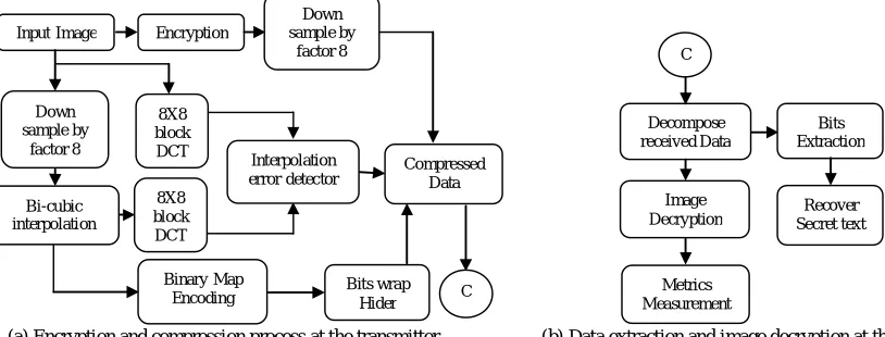
The block diagrams of the proposed method used at the transmitter and at the receiver are shown in Fig 1(a) and Fig 1(b) respectively. At the transmitter, the input image is encrypted and down sampled by a factor of eight. The encryption process is performed with modulo-256addition on the sum of input image and uniformly distributed random matrix. On other hand, the two parts of auxiliary information is also calculated in which the first part is for compression and another one is for decryption process at the receiver. The first part of auxiliary information is calculated based on mean square error between the DCT of the down sampled version and DCT of the interpolated version of the input image. This information is used to compress the data. The interpolation process is performed using Bi-cubic interpolation technique. The second part of the auxiliary information is calculated by performing the XOR operation between the remainders of sum of input image and random matrix and the remainders of sum of interpolated image and random matrix. The remainders are calculated by dividing the both sums mentioned above with 256. The bits wrap hider performs the encryption of binary map and also hides the bits with the bits of cipher text, which is obtained by encrypting the secret key. The compression block compress the received data and transmits to the receiver.
A. Image encryption and compression
The image encryption and compression processes are performed at the transmitter. The block diagram of the encryption and compression process is shown in Fig 1(a). The uncompressed original image is encrypted by adding uniformly distributed random numbers. These random numbers are generated using the secret key with a size of source image and by performing modulo 256 operation. The random numbers are distributed in between [0, 255]. The mathematical representation of encryption process is given in (1).
(, ) (, ),256
,1 1,1 2mod ) ,
(i j ai j ri j i n j n
e (1)
e(i, j)represents the encrypted data at positions (i, j), a(i, j) are source image intensity values and r(i, j) are uniformly distributed random numbers. The pixel values of e(i, j) are also uniformly distributed within [0, 255]. n1 and n2
indicates the rows and columns in source image respectively. Then, the total number of pixels is n=n1 × n2
and the total amount of data in source image is 8×n. If bandwidth of the channel is sufficient then there is no need of other operation, otherwise the content owner has to send auxiliary information for the compression of down sampled encrypted image and for reconstruction of the image at the receiver. Assume that the n1 andn2 are
multiples of 8. The content owner down samples the original image by a factor 8 and interpolates it to its original size using Bi-cubic interpolation technique. This interpolated image is denoted as b(i, j). Then the interpolated and original images are divided into a number of blocks sized 8×8 in order to perform 2D DCT in each block. With viewing the coefficients as 64 sub bands, the content owner calculates the square roots of the average interpolation distortion σ(u,v), which measures the difference between original and interpolated images, in each sub band. This information is the first part of the auxiliary information and the mathematical expression is provided in (2).
64
8 , 8 ( ) 8 , 8 ( )
, (
2 1 1
8
0 1 8
0
2
1 2
n n
v j u i B v j u i A v
u
n
i n
j
(2)
[image:2.612.92.499.561.716.2]Where 1 ≤ u, v ≤ 8. And the second part of the auxiliary information (also called as binary map) is also generated by the content owner using the equation (3).
Fig 1: Block diagram of the proposed method Down
sample by factor 8
Binary Map
Encoding Bits wrap Hider
Compressed Data
C
Input Image Encryption
Down sample by
factor 8
8X8 block
DCT Interpolation
error detector 8X8
block DCT Bi-cubic
interpolation
Decompose received Data
C
Bits Extraction
Recover Secret text Image
Decryption
Metrics Measurement
256 ) , ( ) , ( 256 ) , ( ) , ( ) ,
(i j ai j ri j bi j ri j
m (3)
The values of a(i, j) and b(i, j) are almost similar, hence, most part of the binary map becomes 0 and a small part of it is 1. Therefore, the binary map can be reduced by using RLE algorithm and converted to vector form. Then the compressed data of binary map is encrypted by using bitwise XOR operation and this compressed encrypted data is called as second part of auxiliary information.
) ( ) ( )
(i m i r2 i
me v
Where r2(i)is the uniformly distributed random integer
matrix with values 0 and 1 with the size of mv(i). The
binary bits of me(i) are replaced with the binary bits of
cipher text generated by encrypting the input secret key using Chaos encryption. While encrypting, a hidden secret key is generated with the length of binary equivalent of cipher text. This hidden secret key is used to restore the hidden bits of compressed encrypted data of second part of auxiliary information and cipher text. Then, these two parts of auxiliary information are forwarded to the channel provider. The channel provider takes 2D DCT of encrypted image block by block manner and forms DCT coefficients as given in (4).
8 1 , 8 1 , 64 1 , 8 , 1 ), 8 , 8 ( )
( 12 1 2
) , ( n j n i n n p v u v j u i E p Duv
(4)
Based on the first part of auxiliary information, the quantization parameters are selected for each sub band and are calculated as:
64 1 , 8 , 1 , ) , int( , ) , ( ) ( mod )
( 12
) , ( )
,
( p uv uv p nn
v u preal p D round p Q v u v
u
The compression ratio achieved at the transmitter is calculated using the equation (5).
(5) Where La is the length of auxiliary information. Finally, the
channel provider collects down sampled version of encrypted image, quantization parameters and second part of auxiliary information. This information is transmitted to the receiver through the communication channel.
B. Data Extraction and Image Decryption
The block diagram of the process of image extraction and decryption performed at the receiver is shown in Fig 1(b).The received compressed encrypted image is processed only after the authentication of the user with the use of secret key. Once the user is authenticated then the received data is decomposed into the corresponding sub blocks. The decomposed sub blocks contains that the encrypted sub image, quantization parameters and compressed encrypted version of auxiliary information. The sub image is decrypted by performing the modulo-256 addition on the difference of encrypted sub image and down sampled version of uniformly distributed random matrix. This decrypted image is interpolated to its original size using Bi-cubic interpolation technique. On the other side, the hidden bits of the auxiliary information are restored using the hidden secret key and the resulting auxiliary information is decrypted by performing the XOR operation. The decrypted
auxiliary information is decompressed and restored to its original form. Using this auxiliary information, the values of uniformly distributed random matrix are reorganized to eliminate the errors present in pixel values of the image. Now the approximate version of the original image is reconstructed by adding the interpolated image and resultant random matrix. Then DCT is performed on the approximate reconstructed image and the DCT coefficients are modified using quantization parameters to get the more clarity of the reconstructed image. The resultant image is undergone to inverse DCT and the resultant image is passed through two dimensional wiener filter to remove the adaptive noise in the reconstructed image. The resultant reconstructed image is best viewed with best quality. The flow chart of data extraction and image decryption algorithm is shown in Fig 2.
III. SIMULATION RESULTS
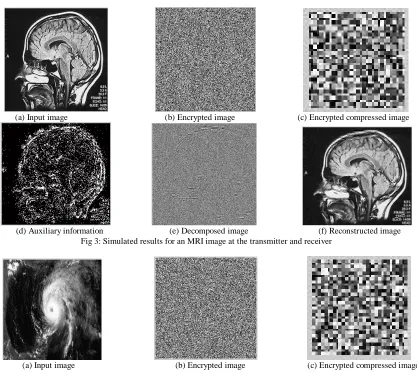
The proposed compressing the encrypted input image at the transmitter and also extraction of data and decryption of the compressed image at the receiver are implemented in MATLAB. The performance of the proposed algorithms is validated with three types of images namely: Magnetic Resonance Imaging (MRI) image, satellite image and image captured by using camera sensors of each size is 256x256.At the transmitter, the uncompressed MRI image, as shown in Fig 3(a), is applied as input to the encryption and compression algorithm. The encrypted and compressed images along with its auxiliary information of MRI image are shown in Fig 3(b)–(d). The achieved compression ratio for MRI image is 0.3094.
The encrypted compressed image is the input image to the data extraction and decryption algorithm. The decrypted and reconstructed images of encrypted compressed image are shown in Fig 3(e) and Fig 3(f) respectively. The Peak Signal to Noise Ratio (PSNR) is also calculated and is 41.6470 dB with a Mean Square Error (MSE) 4.4533.
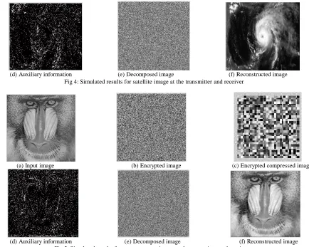
Similarly the performance of the developed algorithms is verified by taking input image as satellite and camera sensor image. The simulated results for the input satellite image and camera sensor image are provided given Fig 4(a)–(f) and Fig 5(a)–(f) respectively. The compression ratio, PSNR and MSE achieved for the satellite image are 0.3046, 41.8024 dB and 4.2938 and for camera sensor image are 0.3059, 42.2839 dB and 3.8432 respectively.
[image:3.612.318.547.663.714.2]The quality of the reconstructed image are measured with the help of compression ratio, PSNR and MSE and these values for all the three images are given in Table I. From the Table I, it is observed that PSNR of the three images is more than 20dB so that the human eye cannot distinguish between the source image and the reconstructed image.
Table I: Quality measurements of reconstructed images
Input image Resolution Compressing
Ratio PSNR(dB) MSE
Satellite 256 X 256 0.3046 41.8024 4.2938
MRI 256 X 256 0.3094 41.6470 4.4533
Camera 256 X 256 0.3059 42.2839 3.8432
Fig 2: Flow chart for data extraction and decryption process at the receiver
(a) Input image (b) Encrypted image (c) Encrypted compressed image
(d) Auxiliary information (e) Decomposed image (f) Reconstructed image Fig 3: Simulated results for an MRI image at the transmitter and receiver
(a) Input image (b) Encrypted image (c) Encrypted compressed image Restore the hidden bits of
Auxiliary information
Decrypt Auxiliary information Decrypt the down sampled version of encrypted image
Start
Decompose the received data Authenticate the user
Get Quantization parameters
Restore Auxiliary information
Get the uniformly distributed random matrix Take DCT
Interpolate the decrypted image
Reconstruct the approximate decrypted image
Take inverse DCT
Get the result by eliminating the adaptive noise through wiener filter
Stop
[image:4.612.104.521.348.721.2][image:5.612.94.528.46.393.2]
(d) Auxiliary information (e) Decomposed image (f) Reconstructed image Fig 4: Simulated results for satellite image at the transmitter and receiver
(a) Input image (b) Encrypted image (c) Encrypted compressed image
(d) Auxiliary information (e) Decomposed image (f) Reconstructed image Fig 5: Simulated results for camera sensor image at the transmitter and receive
IV. CONCLUSIONS
This paper proposed a novel real time steganography technique for the digital images. At the transmitter, an encrypted sub image, the quantized data, the quantization parameters and the second part of the auxiliary information are generated and are transmitted to the receiver. At the receiver, the original uncompressed image is reconstructed using the compressed encrypted data and secrete key. In the proposed method, a rule with ratio-distortion criteria with the aid of auxiliary information is used to select the quantization parameters by the channel provider. Compared with existing methods, the effectiveness of compression is improved and the computational difficulty is significantly made less. The performance of proposed algorithm is verified on various images and the PSNR value is greater than 20dB. This method is so simple to understand and to analyze.
REFERENCES
[1] Daniel Schonberg, Stark Draper, Kannan Ramchandran, “On Compressing Encrypted Data,” IEEE Transactions on Signal Processing, Vol. 52, Issue 10, Oct 2004, pp. 2992–3006.
[2] Zekeriya Erkin, Alessandro Piva, Stefan Katzenbeisser, R. L. Lagendijk, Jamshid Shokrollahi, Gregory Neven and Mauro Barni, “Protection and Retrieval of Encrypted Multimedia Content: When Cryptography Meets Signal Processing,” EURASIP Journal on Information Security, 2007, pp. 1–20.
[3] N. S. Kulkarni, B. Raman, and I. Gupta, “Multimedia Encryption: A Brief Overview,” Recent Advances in Multimedia Signal Processing and Communications Studies in Computational Intelligence, Springer-Verlag, Volume 231, 2009, pp 417-449.
[4] David Slepian, and Jack K. Wolf, “Noiseless coding of correlated information sources,” IEEE Transactions on Information Theory, Vol. 19, Issue 4, July 1973, pp. 471-480.
[5] R. Lazzeretti, and M. Barni, “Lossless Compression of Encrypted Grey-Level and Color Images,” Proceeding of 16th European Signal Processing Conference (EUSIPCO 2008), Lausanne, Switzerland, August 25-29, 2008.
[6] W. Liu, W. Zeng, L. Dong, and Q. Yao, “Efficient Compression of Encrypted Grayscale Images,” IEEE Transactions on Signal Processing, Vol. 19, No. 4, pp. 1097–1102, April 2010.
[7] A. Kumar and A. Makur, “Lossy Compression of Encrypted Image by Compressing Sensing Technique”, Proceedings of IEEE Region 10 Conference (TENCON 2009), 2009, pp. 1-6.
[8] Lixin Luo, Zhenyong Chen, Ming Chen, Xiao Zeng, and Zhang Xiong, “Reversible image watermarking using interpolation technique,” IEEE Transaction on Information Forensics and Security, Vol. 5, No.1, March 2010, pp. 187–193.
[9] Abbes Cheddad, Joan Condell, Kevin Curran, and Paul Kevitt, “Enhancing Steganography in Digital Images,” Proceedings of the 2008 Canadian Conference on Computer and Robot Vision, 2008, pp. 326-332.
[10] Bret Dunbar, “A Detailed look at steganographic techniques and their use in an Open-Systems Environment,” Sans Institute, 2002. [11] Bender. W, Grulh. D, Morimoto. N, and Lu. A, “Techniques for Data
Hiding,” IBM Systems Journal, Volume: 35, Issue: 3.4, 1996, pp. 313-336.