© 2019, IRJET | Impact Factor value: 7.34 | ISO 9001:2008 Certified Journal
| Page 859
PERFORMANCE EVALUATION OF MICRO GRID
Pappu Kumar
1, Dr. Upendra prasad
21
PG Scholar, Department of Electrical Engineering, BIT Sindri, Dhanbad (Jharkhand), India
2Professor, Department of Electrical Engineering, BIT Sindri, Dhanbad (Jharkhand), India
---***---Abstract -
Micro grid is essentially a low voltage or medium voltage conveyance which comprises of a bunch of micro-sources for example, photo voltaic cluster, energy unit, wind turbine and fuel cell. In this work, the dependability and performance analysis of a typical micro grid, compiled with Photovoltaic (PV) arrays and Proton Exchange Membrane Fuel cell (PEMFC) is bestowed. The micro-grid system is designed to operate either in an islanding/autonomous mode to attain the load demand. The Voltage Source Converter (VSC) Controller and Phase Locked Loop (PLL) are based on DQ Transformation. This Transformation is applied to effectually control the -grid voltage, current and frequency and easy flow of power can be achieved from generation to consumption. The voltage as well as the frequency of the proposed micro-grid is consistent even if there is a sudden load or power fluctuation. A dc-dc converter is used to connect the PV and the PEMFC when the State of Charge (SOC) falls to its minimal limit, the rated power can be attained by a backup generator called PEMFC. The propounded PV-PEMFC micro-grid is critically investigated to scrutinize its performance improvisation by extensive simulation analysis to the dc grid. Voltage Source Converter (VSC) helps to maintain the output voltage and output current by enforcing the implementation of Maximum Power Point Tracking (MPPT) techniques by P & O algorithm. The system’s improvement in power quality can be demonstrated with the help of results presented. A relative analysis is carried out to study the proposed system with Voltage source converter (VSC) controller. Using this technique the total harmonic distortion (THD) at the Load common coupling point is improved.Key Words
:
PV Array, PEMFC, MPPT, Voltage Source converter, Phase Locked Loop.
1. INTRODUCTION
Micro grid is a platform for supply –side storage and demand resources located in a local distribution grid. As energy age and circulation organizations contend in the commercial center, we have seen an expanding enthusiasm for sustainable and elective energy sources. Not with standing this opposition, organizations are looking for requests from clients for higher quality and cleaner power. Additionally considering the universes coal stocks are diminishing and the making of enactment which is pushing for greener energy arrangements. A Micro grid should be capable of handling both normal state and emergency state operation.
PV modules are considered as the main source of alternate power generation because of various factors like no
incurring of fuel cost, emission less power generation, long life, less maintenance cost and ease of availability [1]. An optimal configuration of PV arrays with an efficient Maximum Power Point Technique (MPPT) coupled with power electronic converter results in the extraction of maximal power from PV modules. The implementation of Perturb & Observe (P&O) algorithm in this work is because of its simplicity and ease of execution [2]. As a Major energy alternative, fuel cells can be used in DC micro grid and have the following benefits like continuous availability, no emission, better efficiency, less servicing cost and are well matched for DG applications. Most widely used fuel cells in the market are Proton Exchange Membrane Fuel Cell (PEMFC).
The output of PV is normally depends upon the atmospheric conditions and cell temperature and also it is not available during night. So it is an uncontrollable source. To overcome the irrepressible nature of this source, a PEMFC backup generator is used in the integrating. Fuel cell output power can regulate the output power of a Micro grid system even though Fuel cell works only at higher efficiency within a specific range. The different combination of DG systems and their operations in various modes are discussed in detail in literature [4, 5]. The voltage source converter (VSC) is controlled by typical regulators like phase locked loop controller. The conventional techniques requires exact scientific model of the systems and are very receptive to alterations in parameters [6].
© 2019, IRJET | Impact Factor value: 7.34 | ISO 9001:2008 Certified Journal
| Page 860
UG
FUEL CELL PG SYATEM
PV ARRAY PG SYSTEM
DC-DC CONVERTER
DC-DC CONVERTER
DC/AC CONVERTER
PCC TR CB
ELECTRICAL LOADS
Fig 1.1: Block diagram of M-G
2.1 PV MODULE
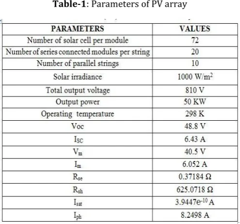
A photovoltaic system basically uses one or more solar modules or panels in series or parallel connection according to the desire of the user to convert solar energy to electrical energy. The components required for a solar PV array are solar panel, electrical connections and mostly MPPT algorithms are used to find the maximum power point of the produced solar power and the photovoltaic cell is the building unit of a photovoltaic array. These cells are made up from semiconductor devices such as germanium, silicon etc. These semiconductor devices are used as very thin wafers who work on the principle of potential difference due to the presence of holes and electrons. Due to the potential difference across the wafer, voltage is produced. Electrons attain energy when subjected to solar radiation and are free to move around. If we connect an electrical circuit with the wafer, we can harness electricity from the wafers. The electricity is produced due to the movement of electrons causing the flow of current .and for low voltage generation in a PV cell (around 0.5V), several PV cells are connected in series (for high voltage) and in parallel (for high current) to form a PV module for desired output. In case of partial or total shading, and at night there may be requirement of separate diodes to avoid reverse currents The p-n junctions of mono-crystalline silicon cells may have adequate reverse current characteristics and these are not necessary. There is wastage of power because of reverse currents which directs to overheating of shaded cells. Athigher temperatures solar cells provide less efficiency and installers aim to offer good ventilation behind solarpanel. Usually there are of 36 or 72 cells in general PV modules. The modules consist of transparent front side, encapsulated PV cell and back side. The efficiency of a PV module is less than a PV cell. This is because of some radiation is reflected by the glass cover and frame shadowing. In any PV system a single PV cell is not enough for generation of energy. The voltage required is met by series connection of these cells and parallel connection is made as per current requirement based on panel ratings. In this paper the data for the solar power plant is considered from the 50KW grid connected solar power plant.
+
_
_
n p
+
_ +
_ +
_ +
_ +
_ +
Photon ≥ Eg
[image:2.595.310.558.247.478.2]Fig 2.1: Representation of semiconductor
Table-1: Parameters of PV array
2.2 MAXIMUM POWER POINT TRACKING
The efficiency of a solar cell is very low and also when solar cells are connected together to form a panel then its efficiency is still not increased [8]. In order to increase the efficiency (𝜂) of solar cell or solar panel we have to use maximum power transfer theorem. The maximum power transfer theorem says that the maximum power is transfer when the output resistance of source matches with the load resistance i.e. solar cell or solar panel impedance. So all MPPT principles are based on maximum power transfer theorem that always trying to matching the impedance of load to source. There are so many methods proposed to find that maximum point [2]. In this paper P&O method is implemented. In this paper MPPT required to maintain 810 V DC voltages as constant. The effectiveness of MPPT is given by following equation.
0
0
(t) dt
(t) dt
t
measured
MPPT t
actual
P
P
© 2019, IRJET | Impact Factor value: 7.34 | ISO 9001:2008 Certified Journal
| Page 861
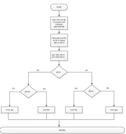
START
Read V(k) and I(k) from panel and Calculate p(k)=V(k)*I(k)
Delay p(k) and V(k) by (K-1) Instant
p(K-1), V(K-1)
p= p(k)- p(k-1) V= V(k)-V(k-1)
P>0
V<0 V<0
D=D- D D=D+ D D=D+ D D=D- D
RETURN
YES NO
[image:3.595.37.292.86.357.2]YES NO YES NO
[image:3.595.318.553.293.411.2]Fig 2.2.1: Flow chart of perturb and Observe Algorithm
Fig 2.2.2: Variation of I-V curve with solar radiation
Fig 2.2.3: Variation of P-V curve with solar radiation
3. FUEL CELL
A fuel cell is an electrochemical device that produces electric power in the form of direct current by converting chemical energy present in the fuel (hydrogen). . Preferably hydrogen is used as a fuel and oxygen is used as an oxidant for Fuel Cells. Although air can be used instead of oxygen but there is decrease in the Fuel Cell efficiency for this kind of arrangement. There are many types of Fuel cell line PEMFC, MCFC, AFC, SOFC. But only PEMFC can be operated at normal air temperature. PEMFC is lightweight so it can be easily transported, used for distribution power generation. There are a number of fuel cells that can be chosen according to the power rating. 1kW FC has the output voltage range of about 25-50 V and 30 kW and above Fuel cells have output voltage of about ( 200-400V).
[image:3.595.44.283.397.515.2]Fig 3.1: Construction of fuel cell
Table -2: chemical reactions in different types of fuel cells
4.
VSC CONTROLLER
[image:3.595.38.290.557.712.2]© 2019, IRJET | Impact Factor value: 7.34 | ISO 9001:2008 Certified Journal
| Page 862
[image:4.595.311.573.76.510.2]active power and ac voltage while the inner loop controls the dq currents. A frame of reference transformation is required for this control. The ac voltages and currents are first transformed into dq quantities via Park’s transformation, and the outer control loop generates the respective dq current references depending on the control objectives. The inner current control loop regulates the dq currents and generates the appropriate switching pulses for converters. Current references depending on the control objectives. The inner current control loop regulates the dq currents and generates the appropriate switching pulses for converters.
Fig 4.1: Simulation model of VSC controller
4 (a).
Transformation from abc reference frame to
dq
0.In the conventional PLL, three-phase voltage vector is
translated from the abc natural reference frame to the αβ stationary reference frame by using Clarke’s transformation, and then translated to dq rotating frame by Park’s transformation as shown in Fig. 4.2. The angular position of this dq reference is controlled by a feedback loop which makes the q-axis component equal to zero in steady state. Therefore, under steady state condition, the d-axis component will be the voltage vector amplitude.
Va
Vb
Vc
abc
αβ
V
Vα
V
βαβ
dq
[image:4.595.307.576.89.293.2]Vq
Fig 4.2: Representation of Discrete transformation
This method utilizes two synchronous reference frames i.e., the voltage vector v is decomposed into positive sequence pharos 𝑣+and negative sequence pharos 𝑣−, as shown in Fig.4.2. In the general equation of 𝑉𝛼𝛽, α- and β-axis components both contain the information of the positive sequence and negative sequence which makes it difficult to detect the positive sequence component.
5. PROPOSED METHODOLOG OF MICRO GRID
PV ARRAY
FUEL CELL MPPT
BOOST CONVERTER
VSC CONTROLLER
VSC CONTROLLER
LC FILTERS in cascade
LC FILTERS in cascade
LOCAL LOAD 1
LOCAL LOAD 2
UTILITY GRID
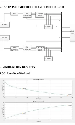
6. SIMULATION RESULTS
6 (a). Results of fuel cell
Fig 6.1: V-I and P-I output characteristics of fuel cell
6(b). Results of PV array
[image:4.595.51.267.254.372.2] [image:4.595.307.573.540.733.2] [image:4.595.39.286.561.656.2]© 2019, IRJET | Impact Factor value: 7.34 | ISO 9001:2008 Certified Journal
| Page 863
6 (c). Three phase RMS voltage and RMS current
waveform outside of inverter.
6 (d)
.
Output power generated in Micro grid
7. CONCLUSION
In recent years many research and developments have been carried out in the field of Micro grid. In this paper many issues related to Micro grid like effective control, power quality and protection have been addressed. Combined output of PV cell and Proton Exchange Membrane fuel cell i.e. 40 KW is connected to the conventional grid and changes in Total Harmonic Distortion are studied. Total harmonic distortion in voltage waveform and current was found to be 1.16 % and 2.55 % respectively at the Load common coupling point. Calculated THD values in this project shows better results. Also, a Micro grid of approximately 40 KW capacities has been designed to operate both in islanded as well as in grid connected mode. The designed system is economical and feasible because it uses Voltage source
converter controller and combination of PV module and fuel cell.
REFERENCES
[1] V. V. P and A. Singh, "A Comparative Analysis of PID and Fuzzy Logic Controller in an Autonomous PV-FC Micro grid," 2018 International Conference on Control, Power, Communication and Computing Technologies (ICCPCCT), Kannur, pp. 381-385.
[2] S. Kauri and B. Dived, " Power quality issues and their mitigation techniques in micro grid system-a review," 7th India International Conference on Power Electronics (IICPE),
Patiala, 2016, pp. 1-4.
[3] P. B. Borase and S. M. Akolkar, "Energy management system for micro grid with power quality improvement," 2017 International conference on Microelectronic Devices, Circuits and Systems (ICMDCS), Vellore, 2017, pp. 1-
[4] K. Tang, C. Sheen, W. Chen, B. Liu, Q. Yuen and Y. Sun, "Micro grid modeling and simulation scenario design for power quality analysis," IEEE PES Asia-Pacific Power and Energy Engineering Conference (APPEEC), Brisbane, QLD, 2015, pp. 1-5.
[5] R. Diva, S. M. Nandukrishnan and M. G. Nair, "Hardware implementation of power sharing and power quality improvement for grid integration of micro grid,"
International Conference on Technological Advancements in Power and Energy ( TAP Energy), Kollam, 2017, pp. 1-6
[7] G. Seritan, I. Triştiu, O. Ceaki and T. Boboc, " Power quality assessment for microgrid scenarios," International Conference and Exposition on Electrical and Power Engineering (EPE), Iasi, 2016, pp. 723-7.