http://www.scirp.org/journal/jst ISSN Online: 2161-1238 ISSN Print: 2161-122X
DOI: 10.4236/jst.2017.72002 Jun. 30, 2017 25 Journal of Sensor Technology
Study of an Omnidirectional Guide Wave
Sensor Using an EMAT
Riichi Murayama, Kazuki Iwaya
Intelligent Mechanical Engineering Department, Fukuoka Institute of Technology, Fukuoka, Japan
Abstract
Nondestructive inspection of structures is important for ensuring the safety of the social infrastructure. Among them, the ultrasonic inspection method plays a role as a major technology. However, when examining a huge structure, the inspection time tends to be very long. Therefore, a system for transmitting and receiving ultrasonic waves in all directions from the ultrasonic sensor has been constructed. Several types of ultrasonic sensors using this concept have already been devised, but since the ultrasonic energy is dispersed in all dire- ctions, there is a problem that a sufficient detection performance cannot be ensured, especially when the thickness of the material to be inspected becomes thick. Therefore, we developed a highly sensitive omnidirectional ultrasonic sensor utilizing the resonance phenomenon of the ultrasonic wave propa- gating in the thickness direction. The omnidirectional ultrasonic system also consists of an electromagnetic ultrasonic transducer (EMAT) using a circular magnet. It is possible to inspect the plate thickness from 0.3 mm to 10 mm and the inspection range of the diameter of 300 mm around the sensor by the developed system. It is indicated that the developed system allows the high- speed inspection of huge structures.
Keywords
EMAT, Surface Wave, Omnidirectional Detection, Inspection
1. Introduction
Periodic inspections are being conducted every 1 to 2 years to ensure the safety of giant structures such as gas tanks and power plants. Depending on the type of the structure, the periodic inspection ranges from 1 to 6 months. This means that it is very important to make the periodic inspection short. For example, in case of an ultrasonic method, an inspector uses an ultrasonic probe with an
ef-How to cite this paper: Murayama, R. and Iwaya, K. (2017) Study of an Omnidirec-tional Guide Wave Sensor Using an EMAT. Journal of Sensor Technology, 7, 25-38.
https://doi.org/10.4236/jst.2017.72002
Received: May 20, 2017 Accepted: June 27, 2017 Published: June 30, 2017
Copyright © 2017 by authors and Scientific Research Publishing Inc. This work is licensed under the Creative Commons Attribution International License (CC BY 4.0).
DOI: 10.4236/jst.2017.72002 26 Journal of Sensor Technology fective range of about 10 mm2 to inspect on earea at a time. Therefore, it takes more than one month to inspect a gas tank. In addition, the ultrasonic sensor using the piezoelectric vibrator requires a medium, such as oil and water, to transmit and receive the ultrasonic wave in the material being inspected [1][2]. In addition, it is very difficult to uniformly paste them on the surface of the ma-terial. If the uniformity cannot be maintained, the reliability of the inspection cannot be assured.
One of the answers to solve this problem is a guide wave because its distance attenuation is rather low. This means that a guide wave can inspect alarge area [3]. For example, inspecting a pipe [4], rail [5], and cold rolled steel [6] using a guide wave has been tried. Furthermore, the inspection of an aircraft has also been reported [7]. However, the success is not sufficient for a large structure and there is still the problem of the couplant. There is a guide wave inspection sys-tem using an air-coupled ultrasonic transducer as a more convenient method because an air-coupled ultrasonic transducer does not need to use a couplant thus why the system can easily move the transducer over the structure [8][9]. However, the performance can be easily affected by the local environment surr- ounding the probe. As another approach, an array system using a PZT-trans- ducer has been studied by many researchers [10][11][12]. However, there is still the problem that the system needs to use a couplant. As an omnidirectional ul- trasonic inspection system that does not require a couplant, an omnidirectional EMAT for transmission using circular array magnets has been reported [13]. Thus a system that combines the omnidirectional transmitter-EMAT for S0, A0, SH0 plate waves, and the receiver-EMATs concentrically placed around the transmitter-EMAT has been developed [14] [15] [16]. An EMAT array system has been also studied [17]. An omnidirectional array system using a magneto-strictive material patch instead of an EMAT has been reported [18][19]. An in-spection system has been proposed using an EMAT consisting of the same shaped circular magnet and an electromagnetic induction coil for the transmit-ter and receiver-EMAT, and using the transmittransmit-ter-EMAT and receiver-EMAT at distance of a few hundred mm [13]. An omnidirectional EMAT for an SH-plate wave has also been developed [20][21].
These reports basically revealed an omnidirectional EMAT for transmission using a circular magnet, but the receiver-EMAT is a system that scans the effec-tive range of the ultrasonic wave transmitted from the transmitter-EMAT around the transmitter-EMAT.
It was not a truly omnidirectional inspection system that used a plate wave or a surface wave. Furthermore, when transmitting or receiving plate waves or sur-face waves by the EMAT, the sensitivity rapidly decreases when the plate thick-ness increases. However, the solution to this problem could not be clearly pre-sented.
DOI: 10.4236/jst.2017.72002 27 Journal of Sensor Technology
[22] as a measure to minimize the thickness concern of the material are prop- osed in this paper.
2. Driving Principle of Integrated Transmitter and Receiver
Omnidirectional Electromagnetic Acoustic Transducer
(Electromagnetic Acoustic Transducer = EMAT) [23] [24]
[25]
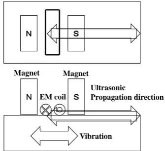
The basic principle is the same as the surface wave EMAT using the magnetos- trictive effect as shown in Figure 1. A biased magnetic field is created in the propagation direction of a surface wave or a plate wave, and a high-frequency induction magnetic field in the same direction is generated by an electroma- gnetic induction coil. The magnetostrictive vibration generated by this complex induction magnetic field induces a surface wave or a plate wave oscillating in the traveling direction [26] [27]. In order to apply this principle to the omnidirec- tional EMAT, a ring-shaped permanent magnet is used. The circular electr- omagnetic induction coil is installed inside the magnet. The concentric high- frequency electromagnetic wave then generates a concentric vibration by them agnetostrictive effect and transforms into an omnidirectional surface wave or a plate wave as shown in Figure 2.
3. Optimization of the Omnidirectional Transmitter-EMAT
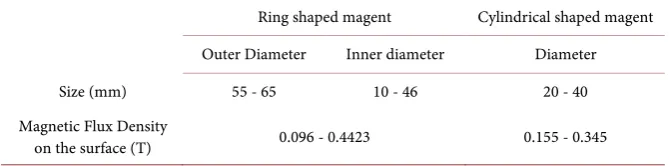
In order to optimize the omnidirectional transmitter-EMAT, it has been invest- igated as how to combine the magnet and the electromagnetic induction coil, in which the inner magnetic flux density becomes an appropriate value using ma-nybar magnets and ring magnetsas shown in Table 1. The optimum electr- omagnetic induction coil to be used has also been studied by changing the di-ameter of the wire and the number of turns.3.1. Experimental Conditions
[image:3.595.288.456.540.693.2]As the first experiment, a steel plate with a thickness of 0.6 mm, a length of 1000 mm, and a width of 1000 was used. The omnidirectional transmitter-EMAT was
Figure 1. Drive principle of a conventional EMAT
for a surface wave.
Ultrasonic
Propagation direction
N S
Magnet
EM coil Magnet
N S
DOI: 10.4236/jst.2017.72002 28 Journal of Sensor Technology
Figure 2. Drive principle of an omnidirectional E-
[image:4.595.206.541.307.390.2]MAT for a surface wave.
Table 1. Specifications of the scale of the magnetsused to obtain the optimum magnetic
flux density.
Ring shaped magent Cylindrical shaped magent Outer Diameter Inner diameter Diameter Size (mm) 55 - 65 10 - 46 20 - 40 Magnetic Flux Density
on the surface (T) 0.096 - 0.4423 0.155 - 0.345
placed at the center of the steel plate. The receiver-EMAT for the surface wave was placed at the distance of 300 mm as shown in Figure 3. In order to deter-mine the influence of the plate thickness, steel plates with a size of 1000 mm × 1000 mm and a thickness of 0.6 mm to 10 mm were also prepared.
Figure 4 shows a diagram of the experimental equipment system. The pulser injects a burst pulse-type high-frequency electrical current of ±50 Vpp to the om-nidirectional transmitter EMAT. On the receiving side, the electrical signal in-jected from the receiver-EMAT was first amplified by the preamplifier with a frequency band of 1 kHz to 1 MHz and the amplification degree of 40 dB. It is then amplified by the degree of 30 dB with the frequency band of 100 kHz to ∞ by the main amplifier. The driving frequency was initially fixed at 800 kHz. The specification of the magnet size used to obtain the optimum magnetic flux den-sity is also shown.
3.2. Experimental Results about How to Combine Both Permanent
Magnets
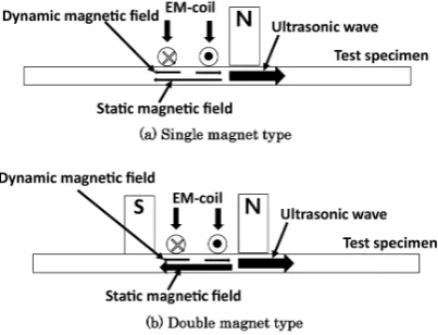
As shown in Figure 5(a), a single ring magnet was first used and a circular elec-tromagnetic induction coil was installed at the inner peripheral edge of the ring magnet. However, as shown in Figure 6(a), a sufficient magnetic flux density could not be obtained, and the received signals having an insufficient S/N ratio were obtained. Therefore, as shown in Figure 5(b), the magnetic flux density
N
Electromagnetic induction coil Ring shaped
permanent magnet
DOI: 10.4236/jst.2017.72002 29 Journal of Sensor Technology
Figure 3. Experimental setup for testing the
[image:5.595.300.441.68.197.2]omnidirectional EMAT using a conventional EMAT as a receiver for a surface wave.
Figure 4. Diagram of the experimental equipment system.
Figure 5. Structure of the omnidirectional transmitter-EMAT.
between the ring magnet and cylindrical magnet was used. The results are shown in Figure 6(b). It was confirmed that it is possible to obtain a magnetic flux density of over 200 mT at the edge position between both magnets. Therefore, the received signal was significantly improved as shown in Figure 6(b) by instal-ling the circular electromagnetic induction coil. Finally, the combination of both magnets was reconsidered so that the most suitable magnetic flux density could be obtained at a position where the electromagnetic induction coil is actually in-stalled between both magnets. As a result, it was possible to obtain a received signal with a sufficient S/N as shown in Figure 6(c).
As a result, the best received signal has been obtained by the combination of a ring-type neodymium magnet with a 40 mm outer diameter × 30 mm inner
Omnidirectional transmitter-EMAT
Receiver-EMAT
300 mm
Signal wave
generator power amplifierHigh frequency Transmitter-EMAT
Receiver-EMAT Pre-amplifier
Amplifier + Filter
[image:5.595.247.503.252.332.2] [image:5.595.273.475.372.526.2]DOI: 10.4236/jst.2017.72002 30 Journal of Sensor Technology
Figure 6. Measurement results of the magnetic flux density and the received signal.
diameter × 10 mm height and a cylindrical magnet of 8 mm diameter × 10 mm height. The magnetic flux density at the position of the electromagnetic induc-tion coil was 0.122 T to 0.193 T. The received signal amplitude was 0.856 V and the S/N ratio was 30.57.
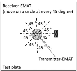
Next, in order to check whether the omnidirectional transmitter-EMAT is transmitting a surface wave in all directions on the sample plate, the received- EMAT was circularly scanned around the omnidirectional transmitter-EMAT as shown in Figure 7 and the received signal was confirmed. It has been confirmed that the surface wave could be transmitted in all directions although there was a variation of about 10% as shown in Figure 8.
4. Omni-Directional Receiver-EMAT
The omnidirectional receiver-EMAT has been developed in order to detect the reflectedultrasonic wave from all directions and the status of the area around the omnidirectional transmitter-EMAT was evaluated.
Experimental Results
DOI: 10.4236/jst.2017.72002 31 Journal of Sensor Technology
Figure 7. Method to obtain the orientation distribution
of the injected surface wave intensity.
Figure 8. Experimental result of the received signal
amplitude distribution in the propagation direction.
Figure 9. Omnidirectional receiver-EMAT using a larger magnet than that
of the omni-directional transmitter-EMAT.
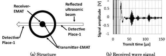
and the group velocity is about 3200 m/s, the signal appeared to be divided into two independent signals. It was confirmed that the time for the shift of the two split signals coincided with the time for propagating between the diameters of the magnetic induction coil for the receiver. That is, as shown in Figure 9(a), when the diameter of the magnetic induction coil for the receiver is large, it is possible to detect the reflected ultrasonic wave at two different positions. There-fore, as shown in Figure 10(a), it is considered that the signal does not split into two parts if the diameter of the electromagnetic induction coil for the receiver is as small as possible with respect to the omnidirectional transmitter-EMAT. The circular electromagnetic induction coil for the receiver has been installed under
Test plate Receiver-EMAT
(move on a circle at every 45 degree)
Transmitter-EMAT
45 °
45 °
45 °
45 °
45 °
45 ° 45 °
45 °
0 0.1 0.2 0.3 0.4 0.5 0.6
0 45 90 135 180 225 270 315 360
S
igna
l
am
pl
it
ude
(V
)
[image:7.595.283.464.242.360.2] [image:7.595.233.512.407.532.2]DOI: 10.4236/jst.2017.72002 32 Journal of Sensor Technology
Figure 10. Omnidirectional receiver-EMAT using a cylindrical magnet
installed at the center of the omnidirectional transmitter-EMAT.
the cylindrical magnet for the transmitter-EMAT to solve this problem. As a re-sult, as shown in Figure 10(b), it was possible to clearly detect the reflected sig-nal from the end the test piece with a sufficient S/N ratio.
Figure 11 shows the detection performance by making a through hole of from 1 mm to 10 mm diameter at positions of 100, 200, 300, and 400 mm from the center of the omnidirectional transmitter and receiver-EMAT. Although the signal intensity sharply decreases as the traveling distance increases, it was con-firmed that a through hole with a diameter of 3 mm can be detected up to a dis-tance of 300 mm.
5. Resonance Experiment Result
Figure 12 shows the relationship between the plate thickness and the received signal amplitude when the driving frequency is 800 kHz. When the plate thick-ness exceeds 2 mm, the signal amplitude rapidly decreases. In addition, the sig-nal cannot be detected for a thickness over 6 mm. Therefore, the resonance me-thod was used as shown in Figure 13. A transverse wave is also generated in the thickness direction by the transverse-EMAT. If the driving frequency is selected at the frequency value corresponding to the reciprocal of the time that the transverse wave propagates in the plate thickness direction, the transverse wave intensity will drastically increase and lead to making the strong guide wave being transformed from the transverse wave as a result.
[image:8.595.232.515.78.174.2]DOI: 10.4236/jst.2017.72002 33 Journal of Sensor Technology
Figure 11. Relationship between the received signal
amplitude and propagation distance.
Figure 12. Relationship between the received signal
[image:9.595.288.460.76.186.2]amplitude and plate thickness.
Figure 13. Concept of the resonance method for the surface wave.
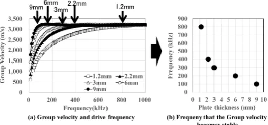
simulator-SWAN21 [28]. The results are shown in Figure 16. The optimum frequency for the 6 mm and 9 mm plates seems to be observed at around a 200 kHz-drive frequency. However, it is unclear for the 2.3 mm thick plate. Figure 17 shows the drive frequency when the A0 mode group velocity is almost con-verging at the same velocity. The frequency is almost the same as the optimum drive frequency determined by the experiment and the calculated resonance
0 5 10 15 20 25 30 35
0 100 200 300 400
Si
gn
al
am
pl
itude
(
S/N
)
Propagation distance (mm) 3mm 5mm 10mm 20mm
0 0.2 0.4 0.6 0.8 1 1.2
0 2 4 6 8 10
Sig
na
l Am
plit
ud
e
[V]
[image:9.595.290.456.234.332.2] [image:9.595.229.517.384.595.2]DOI: 10.4236/jst.2017.72002 34 Journal of Sensor Technology
Figure 14. Received signal reflected by the sheet edge (Distance = 200 mm plate thickness
[image:10.595.208.535.230.399.2]= 9 mm).
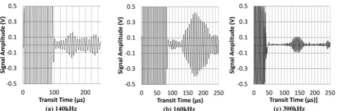
Figure 15. Experimental result of the resonance method.
Figure 16. Generated guide wave intensity using SWAN21.
frequency. For under 6 mm thick plates, at first, the drive frequency when the A0 mode group velocity is almost converging at the same velocity and the calculated resonance frequency is rather different. Next, the EMAT uses an electromagnetic wave to generate and detect an ultrasonic wave. An electromagnetic wave gener-ally decreases in proportion to the square of the frequency. This means that the effect of the resonance phenomenon has been cancelled out. This is why the op-timum drive frequency has not increased as the thickness decreases. In any case, as shown in Figure 18, the received signal with a sufficient strength up to
0 0.1 0.2 0.3 0.4 0.5 0.6
0 100 200 300 400 500
A0
m
ode I
nt
ens
ity
Frequency[kHz]
Thickness=9mm Thickness=2.3mm
[image:10.595.260.490.442.574.2]DOI: 10.4236/jst.2017.72002 35 Journal of Sensor Technology
[image:11.595.196.403.238.381.2]Figure 17. Drive frequency when the group velocity (A0) becomes stable.
Figure 18. Signal amplitude before and after the resonance method.
Figure 19. Reflected signal from any drilled hole.
a thickness of 9 mm was obtained. Figure 19 shows the reflected signal from one of drilled holes. Although it is not a sufficient signal, it was confirmed that the system can detect any defects even if the thickness is 9 mm.
6. Conclusions
An omnidirectional ultrasonic inspection system capable of transmitting and receiving ultrasonic waves in all directions to reduce the inspection time of large area structures has been developed.
0 0.5 1 1.5 2 2.5 3
0 2 4 6 8 10
Si gn al Am pl itu de [V ]
Plate Thickness [mm]
○:before resonance operation
■:after resonance operation
-0.5 -0.4 -0.3 -0.2 -0.1 0 0.1 0.2 0.3 0.4 0.5
0 50 100 150 200 250
Si gna l A m pl itude (V)
Transit Time (μs)
-0.5 -0.4 -0.3 -0.2 -0.1 0 0.1 0.2 0.3 0.4 0.5
0 50 100 150 200 250
Si gna lA m pl itude (V)
Transit Time (μs)
-0.5 -0.4 -0.3 -0.2 -0.1 0 0.1 0.2 0.3 0.4 0.5
0 50 100 150 200 250
Si gna l A m pl itude (V)
Transit Time (μs)
(a) 20mm diameter (b) 10mm diameter (c) 5mm diameter
Flaw signal
[image:11.595.61.541.415.573.2]DOI: 10.4236/jst.2017.72002 36 Journal of Sensor Technology By combining rod-type and cylindrical-type magnets, it was possible to fabri-cate a prototype transmitter and receiver-EMAT which can inspect in all direc-tions. Especially, the cylindrical inner magnet was also used for the receiver- EMAT. The developed EMAT is very simple and small. However, the detection ability dramatically decreased as the thickness of the test specimen increased. The resonance method was then applied to the developed omnidirectional EMAT. Although the optimum drive frequency determined by the experiment was different from the calculated results, the detection ability was dramatically improved even if the plate thickness became thicker.
Of course, it was insufficient for practical use in its detection capability, the scope of inspection, etc. Advanced studies aimed at improving the performance of the receiving ultrasonic probe are continuing.
References
[1] Peter, C. and David, A. (1996) The Use of Lamb Waves for the Long Range Inspec-tion of Large Structures. Ultrasonics, 34, 287-290.
https://doi.org/10.1016/0041-624X(96)00024-8
[2] Cawley, P. (1994) The Rapid Non-Destructive Inspection of Large Composite Structures. Composites, 25, 351-357.
https://doi.org/10.1016/S0010-4361(94)80005-7
[3] Thompson, R.B. (1997) Experiments in the Use of Guided Ultrasonic Waves to Scan Structures. Review of Progress in Quantitive NDE, 16A, 121-128.
[4] Alleyne, D.N., Pavlakovic, B., Lowe, M.J.S. and Cawley, P. (2001) Rapid Long-Range Inspection of Chemical Plant Pipework Using Guided Waves. Insight, 43, 93-96. https://doi.org/10.1063/1.1373757
[5] Wilcox, P., Pavlakovic, B., Evans, M., Vine, K., Cawley, P., Lowe, M. and Alleyne, D. (2003) Long Range Inspection of Rail Using Guided Waves. Review of Progress in Quantitative Nondestructive Evaluation, 22A, 236-243.
https://doi.org/10.1063/1.1570142
[6] Ball, D.F. and Shewring, D. (1973) Some Problems in the Use of Lamb Waves for the Inspection of Cold-Rolled Steel Sheet and Coil. Nondestructive Testing, 6, 138- 145. https://doi.org/10.1016/0029-1021(73)90015-7
[7] Malyarenko, E.V. and Hinders, M.K. (2000) Fan Beam and Double Crosshole Lamb Wave Tomography for Mapping Flaws in Aging Aircraft Structures. The Journal of the Acoustical Society of America, 108, 1631-1639.
https://doi.org/10.1121/1.1289663
[8] Safaeinili, A., Lobkis, O.I. and Chimenti, D.E. (1996) Quantitative Materials Cha-racterization Using Air-Coupled Leaky Lamb Waves. Ultrasonics, 34, 393-396. https://doi.org/10.1016/0041-624X(96)00056-X
[9] Chimenti, D.E. and Song, J. (2007) Performance of Spherically Focused Air Coupled Ultrasonic Transducers. Review of Progress in Quantitative Nondestructive Evalua-tion, 26, 862-869. https://doi.org/10.1063/1.2718059
[10] Miao, H.C. and Li, F.X. (2015) Realization of Face-Shear Piezoelectric Coefficient d(36) in PZT Ceramics via Ferroelastic Domain Engineering. Applied Physics Let-ters, 107, 122902. https://doi.org/10.1063/1.4931685
DOI: 10.4236/jst.2017.72002 37 Journal of Sensor Technology 118, Article ID: 214102.https://doi.org/10.1063/1.4936781
[12] Belanger, P. and Boivin, G. (2016) Development of a Low Frequency Omnidirec-tional Piezoelectric Share Horizontal Wave Transducer. Smart Materials and Struc-tures, 25, Article ID: 045024.https://doi.org/10.1088/0964-1726/25/4/045024 [13] Songling, H., Zheng, W., Wei, Z. and Shen, W. (2014) A New Omni-Directional
EMAT for Ultrasonic Lamb Wave Tomography Imaging of Metallic Plate Defects. Sensors, 14, 3458-3476. https://doi.org/10.3390/s140203458
[14] Paul, D.W. (2003) Omni-Directional Guided Wave Transducer Arrays for the Rap-id Inspection of Large Areas of Plate Structures. IEEE Transactions on Ultrasonics, Ferroelectrics, and Frequency Control, 50, 699-709.
[15] Wilcox, P.D., Lowe, M. and Cawley, P. (2005) Omnidirectional Guided Wave In-spection of Large Metallic Plate Structures Using an EMAT Array. IEEE Transac-tions on Ultrasonics Ferroelectrics and Frequency Control, 52, 653-665.
https://doi.org/10.1109/TUFFC.2005.1428048
[16] Wilcox, P.D., Lowe, M.J.S. and Cawley, P. (2005) The Excitation and Detection of Lamb Waves with Planar Coil Electromagnetic Acoustic Transducers. IEEE Trans-actions on Ultrasonic Ferroelectrics and Frequency Control, 52, 2370-2383.
https://doi.org/10.1109/TUFFC.2005.1563281
[17] Koduru, J.P. and Rose, J.L. (2013) Transducer Arrays for Omnidirectional Guided Wave Mode Control in Plate like Structures. Smart Materials and Structures, 22, Article ID: 015010.https://doi.org/10.1088/0964-1726/22/1/015010
[18] Vishnuvardhan, J., Muralidharan, A., Krishnamurthy, C.V. and Balasubramaniam, K. (2009) Structual Health Monitoring of Anisotropic Plate Using Ultrasonic Guided Wave STMR Array Patches. NDT & E International, 42, 193-198.
[19] Dee, J.K., Kim, H.W. and Kim, Y.Y. (2013) Ominidirectional Lamb Waves by Axi-symmetrically-Configured Magnetostrictive Patch Transducer. IEEE Transactions on Ultrasonics Ferroelectrics and Frequency Control, 60, 1928-1931.
https://doi.org/10.1109/TUFFC.2013.2777
[20] Seung, H.M., Kim, H.W. and Kim, Y.Y. (2013) Development of an Omini-Direc- tional Shear-Horizontal Wave Magnetostrictive Patch Transducer for Plates. Ultra-sonics, 53, 1304-1308.
[21] Seung, H.M., Park, C. and Kim, Y.Y. (2016) An Omnidirectional Shear-Horizontal Guided Wave EMAT for a Metallic Plate. Ultrasonics, 69, 58-66.
[22] Otani T., Ogi, T. and Hirao, M. (2000) Ultrasonic Attenuation Monitoring of Fati-gue Damage in Low Carbon Steels with Electromagnetic Acoustic Resonance (EMAR). Journal of Alloys and Compounds, 310, 440-444.
[23] Thompson, R.B. (1973) A Model for the Electromagnetic Generation and Detection of Rayleigh and Lamb Wave. IEEE Transactions, SU-20, 340-346.
[24] Thompson, R.B. (1980) The Relationship between Radiating Body Forces and Equivalent Surface Stresses: Analysis and Application to EMAT Design. Journal of Nondestructive Evaluation, 1, 79-85.https://doi.org/10.1007/BF00566116
[25] Koorosh, M., Chris, C., Chris, M., Maciej, J., Anthony, S., Reza, J.S., Adalbert, K. and Marcello, P. (2004) Optimal Design of EMAT Transmitters. NDT & E Interna-tional, 37, 181-193.
[26] Hirao, M. and Ogi, H. (2004) Development of EMAT Techniques in EMATS for Science and Industry. Kluwer Academic Publishers, London.
DOI: 10.4236/jst.2017.72002 38 Journal of Sensor Technology 1043.
[28] Japan Probe Ltd. (2013) Ultrasonic Propagating Simulator SWAN21. http://www.jp-probe.com/en/product/?ca=18&res_id=1406019676-328879
Submit or recommend next manuscript to SCIRP and we will provide best service for you:
Accepting pre-submission inquiries through Email, Facebook, LinkedIn, Twitter, etc. A wide selection of journals (inclusive of 9 subjects, more than 200 journals)
Providing 24-hour high-quality service User-friendly online submission system Fair and swift peer-review system
Efficient typesetting and proofreading procedure
Display of the result of downloads and visits, as well as the number of cited articles Maximum dissemination of your research work