On-grid and Off-grid Operation of Multi-Input Single-Output
DC/DC Converter based Fuel Cell Generation System
R. Noroozian*, M. Abedi**, G. B. Gharehpetian** and S. H. Hosseini***
Abstract: This paper presents the modeling and simulation of a proton exchange membrane fuel cell (PEMFC) generation system for off-grid and on-grid operation and configuration. A fuel cell DG system consists of a fuel cell power plant, a DC/DC converter and a DC/AC inverter. The dynamic model for fuel cell array and its power electronic interfacing are presented; also a multi-input single output (MISO) DC/DC converter and its control scheme is proposed and analyzed. This DC/DC converter is capable of interfacing fuel cell arrays to the DC/AC inverter. Also the mathematical model of the inverter is obtained by using average technique. Then the novel control strategy of DC/AC inverter for different operating conditions is demonstrated. The simulation results show the effectiveness of the suggested control systems under both on-grid and off-grid operation modes.
Keywords: distributed generation (DG), modeling, PEM fuel cell (PEMFC), operation, and power electronic interface.
1 Introduction 1
The fuel cells can be used in the cars, buildings, hospitals, hotels, industrial facilities fast food outlets, etc. These applications have two off-grid and on-grid operation modes [1].
The fuel cells generate DC electrical energy from hydrogen by using a chemical process and their emissions are water. Therefore, power electronic circuits are an enabling technology that is necessary to convert DC electrical power generated by a fuel cell into usable AC power for passive loads, automotive applications, and interfaces with electric utilities. The fuel cell DG system is interfaced with the utility network via boost DC/DC converters and a three-phase pulse-width modulation (PWM) DC/AC inverter. In recent decades, various power electronic circuits have been proposed to interface fuel cell DG system with the
Iranian Journal of Electrical & Electronic Engineering, 2009.
Paper first received 25 Sep. 2008and in revised form 27 Dec. 2008.
* R. Noroozian is with the Department of Electrical Engineering, Faculty of Engineering, University of Zanjan, P.O.Box 45195-313, Zanjan, Iran.
E-mail: [email protected].
** M. Abedi and G. B. Gharehpetian are with the Department of Electrical Engineering, Amirkabir University of Technology, Tehran, Iran.
E-mail: [email protected]; [email protected]
*** S. H. Hosseini is with the Department of Electrical Engineering, Tabriz University, Tabriz, Iran.
E-mail:[email protected].
utility grid [1-4]. The DC voltage generated by a fuel cell stack varies widely and is low in magnitude. Therefore, a boost DC/DC converter is necessary to generate a regulated higher voltage DC for desired inverter input voltage. The boost DC/DC converter is responsible for drawing power from the fuel cell, and therefore should be designed to match fuel cell ripple current specifications. Conventional DC/DC converters, such as push-pull, half bridge and full-bridge converters can be used to boost the low voltage of the fuel cell to the required level. However, the transformers in these converters have considerable turns ratios (such as 1:20), and hence, high leakage inductances, which results in low energy efficiency and difficulty in control of the DC/DC converter [5]-[6]. DC/DC boost converters are usually used to interface the DC output of fuel cell units with the utility network. The static (V-I) characteristics of fuel cells show more than a 30% difference in the output voltage between no load to full-load conditions [7-8]. This inevitable decrease, which is caused by internal losses, reduces the utilization factor of the fuel cells at low loads. To increase the utilization of fuel cells, this paper, multi-input single-output (MISO) DC/DC converter for fuel cell arrays, which provides well-regulated output voltage, has been presented and analyzed. The advantages of this converter are its simple configuration, fewer component number, lower cost and higher efficiency. Another advantage of MISO
DC/DC converters is that their switching frequency can be lower than a traditional converter, which means reduced switching losses and increased efficiency. Therefore, the MISO DC/DC converter is useful for combining fuel cell arrays.
The DC/AC voltage source inverter (VSI) has been widely used to interconnect a fuel cell energy system to a utility grid under both on-grid and off-grid operations [1], [4]. The control strategy of the DC/AC inverter should be able to deliver a preset amount of active and reactive power to the grid or be able to supplying the isolated unbalanced AC load by constant balanced AC voltage magnitude and frequency. Therefore, the DC/AC inverter controller in on-grid mode controls the active and reactive power flows to the utility grid. Therefore, a novel and simple control system based instantaneous power control strategy has been proposed and developed for DC/AC inverter [9-11].
The DC/AC inverter controller in off-grid operating mode regulates the voltage and the frequency of isolated unbalanced load. Therefore, a novel control system
based on d−q−0 rotating frame has been proposed for
DC/AC inverters. In d−q−0 rotating frame, the load
current and voltage components in the d−q channels
are given rise to 2ω current ripples. The zero
component appears as a disturbance at ω [12-14].
These three sequences are regulated independently by the Proportional Integral (PI) controllers.
This paper presents the modeling and controlling of fuel cell generation system under off-grid and on grid modes. Also, the mathematical model of the DC/AC inverter is derived by using the average large signal model. Two separate novel controllers are designed for these purposes. The proposed system has been modeled and simulated. The simulation results show the generated power from the fuel cell DG system can be controlled.
The results also show that the fuel cell generation system is capable to supplying the unbalanced AC loads by constant balanced AC voltage magnitude and frequency
2 System Configuration
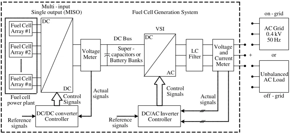
Fig. 1 shows the schematic diagram of the fuel cell generation system, which has been studied in this paper. The basic components of this system are the fuel cell power plant, MISO DC/DC converter and DC/AC inverter. A validated 500 W PEMFC dynamic model, reported in [15], is used to model the fuel cell power
plant. The fuel cell power plant consists of n fuel cell
arrays connected in parallel. The MISO DC/DC converter is used to boost the low voltage of the fuel cell to make a high voltage DC bus. In this paper, the DC bus voltage (MISO DC/DC converter output) is
chosen as Vdc=750V. The controllers of the boost
DC/DC converters are designed to keep the DC bus
voltage within specified limit (±5%). The DC/AC
inverter is a three-phase six-switch VSI with neutral clamped DC capacitors, which interfaces the DC bus
with a 220V/400V AC power system. An LC filter
connected to the inverter filters the switching frequency harmonics and generates a high quality sinusoidal AC waveform suitable for the load. The VSI controller in on-grid mode controls the active and reactive power delivered from the fuel cell energy system to the utility grid. The active and reactive power flows follow within specified reference values, which can be set by using power management units. The VSI controller in off-grid operating mode regulates the unbalanced load voltage of balanced and sinusoidal with constant amplitude and frequency. Supercapacitors or battery banks are connected to the DC bus to provide energy storage capability under different operating conditions.
(MISO) output Single
input -Multi
#1 Array
Cell Fuel
#2 Array
Cell Fuel
n # Array
Cell Fuel
DC
DC
DC
AC Banks
Battery or capacitors
-Super
Filter LC Meter
Voltage
Meter Current
and Voltage
Hz 50
kV 0.4
Grid AC
grid -on
grid -off
Load AC Unbalanced
Signals Control
Signals Control
Controller converter DC/DC
Controller Inverter DC/AC
signals Reference
Bus DC
or
+
System Generation Cell
Fuel
signals Actual plant
power cell
Fuel signals
Actual
signals Reference
VSI
Fig. 1. Fuel cell generation system.
3 Dynamic Models for Fuel Cell Array
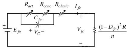
Fig. 2 shows the electrical circuit model that describes the dynamic behaviour of fuel cell for its electrical terminals [15]. In Fig. 1, Efc is the equivalent internal potential and activation voltage drop. Ract, Rconc, and Rohmic are the equivalent resistances of activation, concentration, and ohmic voltage drops inside the fuel cell stack, respectively. These resistors are current (Ifc)
and/or temperature (T) dependent. Cfc represents the
equivalent capacitance of the system. VC represents the voltage across of equivalent capacitance. Dfc is the duty cycle of each boost converter. Vfc and Ifc is the output voltage and current of each fuel cell array, respectively. R is the equivalent resistance of load for MISO DC/DC converter.
In Fig 2, we have:
fc fc fc a
C C
C I C R
V dt
dV
+ −
= (1)
fc ohmic C fc
fc E V R .I
V = − − (2)
fc 2 fc
fc I
n R ) D 1 (
V = − (3)
where, Ra=Ract+Rconc, τfc=RaCfc is the time constant of associated to activation and concentration voltages.The activation and concentration losses represent a delay in the fuel cell output voltage. Corresponding to equation (3), the power supplied by the fuel cell to the load is depending on the operating point set by the duty cycle and the number of fuel cell arrays.
In this paper, the fuel cell current is 20 A (rated operating point) and its output voltage (Vfc,cell) is about 27 V [4], [15]. Therefore, the number (Ns) of fuel cell stacks we need to connect in a series to get a voltage of
V 108 is
. 4 27 108
= =
s
N (4)
The total power rating of the series connection of 4 PEMFC stacks (0.5 kW each) is 2 kW. The number (Np) of these 2 kW PEMFC units that need to be connected in parallel to compose a 30 kW fuel cell array is
. 15 kW 0.5 4
kW 30
= ×
= × =
stack s
array p
P N
P
N (5)
Therefore, each fuel cell array is composed of 15
4× stacks with the power rating of 30 kW.
4 MISO DC/DC Converter
The output voltage of fuel cells at the series of the stacks is uncontrolled DC voltage, which fluctuates with load variations as well as with the changes in the fuel input. It has to be controlled by DC/DC boost converter.
The MISO DC/DC converter topology used for the combination of DC output of fuel cell power array is shown in Fig. 3.
fc
C
fc
I
fc V act
R
+
− conc
R
fc
E +
−
ohmic R
n R Dfc
2 ) 1
( −
+ −
C V
Fig. 2. Electrical model of PEMFC.
The low voltage inputs of fuel cells, i.e., Vfc1, Vfc2, Vfc3 and Vfcn have been connected to the DC bus by series connected boost converters. The single output of DC/DC converter is fed to the DC/AC inverter, to produce the AC output for AC grid under both on-grid and off-grid modes. The power flow and output voltage of fuel cells have been controlled by controlling the duty cycles of n IGBT switches, Sfc1, Sfc2, Sfc3 and Sfcn. The output voltage of MISO DC/DC converter Vdc can be expressed by the following (6):
n fc fcn 2
fc 2 fc 1 fc 1 fc
dcn 2
dc 1 dc dc
D 1
V ... D 1
V D 1
V
V ... V V V
− + + − + − =
+ + + =
(6)
where Dfc1, Dfc2, Dfc3 and Dfcn are the duty cycles of boost converters and Vdc1, Vdc2, Vdc3 and Vdcn are the output voltages of boost converters. If the converter duty cycles and their inputs are equal, the output voltage of MISO DC/DC converter, i.e., Vdc, can be determined by the following (7):
fc fc
dc V
D 1
n V
−
= (7)
where Dfc is the duty cycle of each boost converter, Vfc is the low voltage input of each fuel cell array. Vdc is the output voltage of boost converters.
The output current of MISO DC/DC converter Idc can be expressed by the following (8):
) D 1 ( I ...
) D 1 ( I ) D 1 ( I I
n fc fcn
2 fc 2 fc 1 fc 1 fc dc
− = =
− = − =
(8)
where Ifc1, Ifc2, Ifc3 and Ifcn are the input currents of boost converters, If the converter duty cycles and their inputs are equal, the output current of MISO DC/DC converter, i.e., Idc, can be determined by the following (9):
) D 1 ( I
Idc = fc − fc (9)
where Ifc is the input current of each fuel cell array. Applying now Ohm’s law on the resistance R , we have:
dc
dc RI
V = (10)
Using equations (7), (9) and (10), the equivalent resistance in the fuel cell from its terminals is given by
n R ) D 1 ( R
2 fc fc
−
= (11)
The value of capacitor of each boost converter can be determined as follows:
dc s fc
fc fc fc
V
∆
f R
V ) D 1 ( nD
C= − (12)
where f is the switching frequency, ∆Vdc is the output
voltage ripple of DC/DC converter. The value for inductor of each boost converter can be determined by the following (13):
s fc fc
f 2
R . D
L= (13)
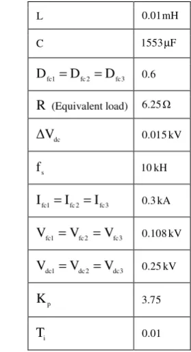
In the control system of MISO DC/DC converter, the output voltage of converter has been compared with a reference value and the error signal is applied to PI-controller. The PI controller (Kp+1/Tis) can be designed using the classic Bode-plot and root-locus method. The output signal of this controller is the one input of PWM switching for adjust the duty cycle. Therefore, the output voltage follows the reference value. In this paper, as an example a triple input single output (TISO) DC/DC converter has been designed and studied. The main components of the dc/dc converter can be determined by the prescribed technical specifications, such as the rated and peak voltage and current, input current ripple, and output voltage ripple, etc., using the equations (7) to (13). The component values for the 90-kW TISO DC/DC converter used in this paper are listed in Table 1.
5 DC/AC Voltage Source Inverter
The DC/AC voltage source inverter exchanges power between the utility grid and the DC bus and vice versa. On-grid (or grid-connected) mode allows the DC/AC inverter to operate parallel to the grid, providing grid support. Off-grid (or stand-alone) mode allows the DC/AC inverter to operate completely isolated from AC grid. There can be a dual mode of operation. In this mode, DC/AC inverter could be automatically switched between the two modes.
5.1 Control Strategy for the On-grid Operation The average large signal model of the DC/AC inverter in on-grid operating condition is shown in Fig. 4. This converter is represented with three ideal current
sources ifaref, ifbref and ifcref. The converter manages the
amount of the current injected to AC grid from the DC
bus. As it can be seen in Fig. 4, the input signals of the DC/AC inverter are source phase voltages, vsa, vsb and vsc, three phase output currents for this converter ifa, ifb and ifc, the reference of the active power, Pref and the reference of the reactive power, Qref. Lf is the inductance of the inverter filter. Rg, and Lg are the resistance and inductance of the AC grid. This controller uses the Hysteresis Current Control (HCC) switching technique. As it can be seen in Fig. 4, we have:
− =
fc fb fa
sc sb sa
i i i
i i i
(14)
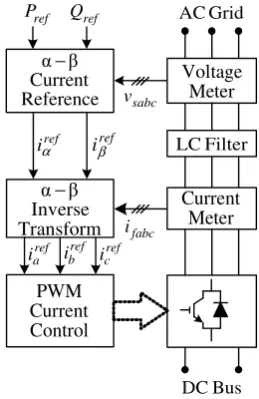
Fig. 5 shows the DC/AC inverter control in on-grid operation. The required power to be injected to AC grid is set by Pref and Qref reference signals. These signals can be chosen by customers or remote power management units [9-11]. However, this control strategy is called P−Q control scheme for on-grid operation.
Table 1. Parameters of TISO DC/DC converter.
L 0.01mH
C 1553µF
3 fc 2 fc 1
fc D D
D = = 0.6
R (Equivalent load) 6.25Ω
dc V
∆ 0.015kV
s
f 10kH
3 fc 2 fc 1
fc I I
I = = 0.3kA
3 fc 2 fc 1
fc V V
V = = 0.108kV
3 dc 2 dc 1
dc V V
V = = 0.25kV
p
K 3.75
i
T 0.01
In this paper, the P−Q control strategy has been
designed based on the instantaneous power control
strategy. The α−β transformation in Fig. 5 performs
the following equations:
=
αβ β α
sc sb sa
s s
v v v T v v
(15)
− − − − = αβ 2 3 2 3 0 2 1 2 1 1 3 2 T
The α−β component related to the reference
current of each network converter can be expressed by equation (16).
−
+
=
α β β α β α β α ref ref s s s s 2 s 2 s ref s ref sQ
P
v
v
v
v
v
v
1
i
i
(16) + C − 1 fc S 1 fc I 1 fc V L 1 dc V + − dc I + + C − 2 fc S 2 fc I 2 fc V L 2 dc V + − + C − 3 fc S 3 fc I 3 fc V L 3 dc V + − + C − fcn S fcn I fcn V L dcn V + − − dc V R 1 fc D 2 fc D 3 fc D fcn DFig. 3. Multi-input and single output (MISO) DC/DC converter.
The α−β inverse transformation box, shown in Fig.
5, calculates the three-phase current references to be fed into the HCC scheme. Thus:
=
β α ref s ref s abc ref sc ref sb ref sai
i
T
i
i
i
(17-a) − − − = 2 3 2 1 2 3 2 1 0 1 3 2 abc T (17-b)
−
=
ref sc ref sb ref sa ref fc ref fb ref fai
i
i
i
i
i
(18)The comparison of the calculated reference currents and the actual currents generated by the DC/AC inverter will result in the error signal, which controls the switches of the inverter.
dc
V Idc
fa v fb v fc v fa i fb i fc i f L sa v sb v sc v sa i sb i sc i g
L Rg
ref fc
i ireffb ireffa
Controller Inverter DC/AC vsa
sb v sc v fa i fb i fc i Hz 50 kV 0.4 Grid AC ref
P Qref
+ − 1 C 2 C
Fig. 4. Average large signal model of the DC/ AC inverter in on-grid mode.
Transform Inverse β α− Control Current PWM ref iβ ref
iα LCFilter
Bus DC Meter Current Meter Voltage Grid AC Reference Current β α− ref Q ref P ref c i ref b i ref a i fabc i sabc v
Fig. 5. Block diagram of DC/AC inverter controller in on-grid operation.
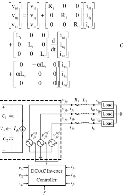
5.2 Control Strategy for the off-grid Operation The average large signal model of the DC/AC inverter in off-grid operating condition is shown in Fig. 6. This inverter is represented with three voltage sources, vfaref, vfbref and vfcref. The equations describing DC/AC inverter voltages and currents are expressed by the following equation:
+ + = fc fb fa f f f fc fb fa f f f lc lb la fc fb fa i i i dt d L 0 0 0 L 0 0 0 L i i i R 0 0 0 R 0 0 0 R v v v v v v (19)
where, vfa, vfb and vfc are line to neutral three phase output voltages of the DC/AC inverter. ifa, ifb and ifc are three phase output currents. vla, vlb and vlc are line to neutral three phase voltages of AC loads. The voltage equations in the d−q−0 reference frame are as follows: ω ω − + + + = 0 f fq fd f f 0 f fq fd f f f 0 f fq fd f f f 0 l lq ld 0 f fq fd i i i 0 0 0 0 0 L 0 L 0 i i i dt d L 0 0 0 L 0 0 0 L i i i R 0 0 0 R 0 0 0 R v v v v v v (20) ref fc v fa v fb v fc v fa i fb i ref fa v vreffb
Controller Inverter DC/AC f fa i fb i fc i lc v lb v la v Load fc i f L lc i lb i la i Load Load lb v la v lc v f R dc
V Idc + − 1 C 2 C
Fig. 6. Average large signal model of the DC/ AC inverter in off-grid mode.
The circuit configuration and control scheme for DC/AC inverter for supplying unbalanced AC load is depicted in Fig. 7. The DC/AC inverter between the DC bus and AC load can be controlled by V−f control strategy, which regulates the voltage and the frequency of AC load [12-14]. In the V−f controller, it is clear that:
a. Frequency (ω) can be obtained by Phase Lock Loop (PLL) using desirable frequency (e.g., 50 Hz).
b. The load phase voltages (vla, vlb and vlc) can be detected and transformed to the d−q−0 synchronously rotating reference frame using following equations:
=
lc lb la 0 dq 0 l lq ld v v v T v v v (21) + ω − − ω − ω − + ω − ω ω = 2 1 2 1 2 1 ) 120 t sin( ) 120 t sin( ) t sin( ) 120 t cos( ) 120 t cos( ) t cos( 3 2Tdq0 o o
o o
Transform 0 q
d− −
Load AC Meter Voltage Filter LC Bus DC lq v ld
v vl0
exp lq v exp ld v exp l v0 Meter Current PI PI PI PI PI PI PI PI PI 0 ldq v lq v ld v 0 l v ω ref fa v ref fb v ref fc v Transform 0 q
d− −
fq i fd
i if0
f L ω fabc i Control Voltage PWM ω f PLL labc v fq i fd i 0 f i − + − + − + ref lq i ref ld
i ilref0 − + − + − + + + + + + − + + ref fd
v vreffq vreff0
Transform Inverse
0 q
d− −
ω f R f L ω f R + + + + +
Fig. 7. Block diagram of DC/AC inverter controller in off-grid operation.
The load phase voltage should be kept balanced and sinusoidal with constant amplitude and frequency. Therefore the expected load voltage in the d−q−0 reference frame should have only the following value:
=
0 3 2 .4 0 0 v v v exp 0 l exp lq exp ld (22)The inverter controller based on d−q−0 rotating reference frame consists of an inner current loop and an outer voltage loop in a three channel arrangement. The current and voltage loops include independent PI controllers for the d , q and 0 channels to eliminate steady state error. The reference load current loops in the d−q−0 coordinate are:
−
−
−
=
) v v ( PI ) v v ( PI ) v v ( PI i i i exp 0 l 0 l exp lq lq exp ld ld ref 0 l ref lq ref ld (23)The output signals from PI controller can be expressed by the equation (19).
ω ω − − − −
+
+
=
0 i R i R 0 i L i L ) i i ( PI ) i i ( PI ) i i ( PI v v v v v v fq f fd f fd f fq f 0 f ref 0 l fq ref lq fd ref ld 0 l lq ld ref 0 f ref fq ref fd (24)The reference output voltages for the DC/AC
inverter are transformed to the a−b−c by using
inverse synchronously rotating frame.
=
ref 0 f ref fq ref fd abc ref fc ref fb ref fa v v v T v v v (25) + ω − + ω − ω − − ω ω − ω = 1 ) 120 t sin( ) 120 t cos( 1 ) 120 t sin( ) 120 t cos( 1 ) t sin( ) t cos( Tabc o o o oThen the available voltages in the a−b−c
coordinate are compared with the triangular wave provided by PWM voltage control block. Therefore the output provides suitable switching pattern of DC/AC inverter.
6 Simulation Results
In this paper, to evaluate the performance of fuel cell generation system, on-grid and off-grid operating conditions have been modeled by PSCAD/EMTDC. The control strategy of DC/AC inverter with neutral clamped DC capacitors has been studied in on-grid and off-grid operation modes.
6.1 On-Grid Operation
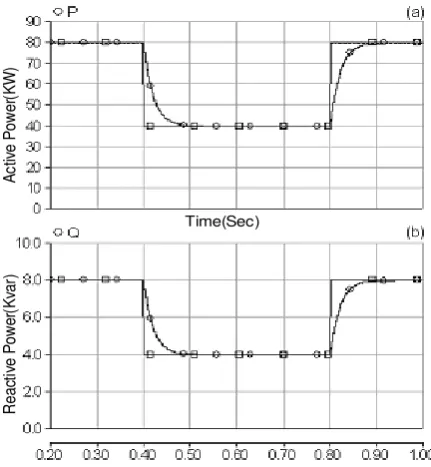
In this case, the reference values of Pref and Qref have been changed from 80 kW to 40 kW and from 8 kVAr to 4 kVAr at t=0.4s, and then from 40 kW to 80 kW and from 4 kVAr to 8 kVAr at t = 0.8 sec., respectively. Figures 8 to 11 show the simulation results. As shown in Fig. 8, the active power injected to the AC grid has been changed from 80 kW to 40 kW at t = 0.4 sec., and then from 40 kW to 80 kW at t = 0.8 sec. In Fig. 8, the reactive power has been changed from the AC grid by the fuel cell unit is changed from 8 kVAr to 4 kVar at t = 0.4 sec. and then from 4 kVAr to 8 kVar at t = 0.8 sec. As it can be seen the parameters follow the reference points and in the steady-state, the fuel cell generation system delivers the active power to the grid and consumes the reactive power from the grid, which matches the reference values of P and Q . The filtered output voltages and currents of each fuel cell array for this case are shown in Fig. 9.
As depicted in Fig. 9, the fuel cell current has some delay because it takes some time for the fuel to be converted to the hydrogen, which is demanded for the request power, and the fuel cell voltage and current depend on each other as voltage-current polarization curve of the stack. Fig. 10(a) shows the active power injected to the DC bus. Corresponding to the Fig. 10(a), active power injected into the DC bus by using fuel cell power plant increases and reach to reference value, which match the above active power reference variation. Fig. 10(b) show the DC bus voltage (the output of TISO DC/DC converter), which match the above grid connected condition. Note that the DC bus voltage comes up to its reference value, 750 V though the fuel cell output voltage is fluctuated in during the simulation time. The voltage ripple at the DC bus is about 1.2%, which is with the acceptable range.
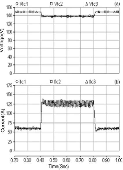
Fig. 11 shows grid-side phase voltages and line currents of the DC/AC inverter. The line currents changes with power reference variations, which goes into the utility grid. Therefore, the inverter can deliver the generator’s power of fuel cell DG system to the grid with low harmonic current. This verifies the
effectiveness of the P−Q control strategy.
6.2 Off-Grid Operation
The response of proposed fuel cell generation system to unbalanced resistive-inductive loading in the off-grid mode has been studied, too. Therefore, the
f
V− control scheme is activated. The unbalanced load
No. 1 has been changed to unbalanced load No. 2 at t=0.4s and at t=0.8s the load has been again changed to its initial value, i.e., load No. 1. The load parameters are given in appendix A. Figures 12 to 15 show the simulation results. Fig. 12 shows the active and reactive power consumed by unbalanced loads. As shown in Fig.
12, the fuel cell generation system is supplying the unbalanced AC loads. The filtered output voltage and current curves of each fuel cell array for this case are shown in Fig. 13. As depicted in Fig. 13, the some delay of fuel cell output voltage and current depend on each other as voltage-current polarization curve of stack. Fig. 14(a) shows the power injected to the DC bus. Corresponding to the Fig. 14(a), power injected into the DC bus by using fuel cell increases and reach to load demand, which match the above unbalanced load requirement. Fig. 14(b) shows the DC bus voltage (the output of TISO DC/DC converter), which match the above load variations. Note that the DC bus voltage comes up to its reference value, 750 V though the fuel cell output voltage is fluctuated in during the simulation time. The voltage ripple at the DC bus is about 1.2%, which is with the acceptable range.
Fig. 15 shows phase voltages and line currents at unbalanced load terminals. The DC/AC inverter maintains the output at the desired level irrespective of unbalanced loads applied on the system.
The AC voltage level across the load remains unchanged with the unbalanced load variation switching
and stay at the reference value Vlqexp in the all time of
simulation. However, the balanced voltages are provided for the unbalanced AC loads while the load phase currents are not sinusoidal. This is because of ability of DC/AC inverter to control its output voltage. The 3-phase line current at load terminals changes with the load variation switching. The frequency (50 Hz in our case) is imposed by a phase lock loop (PLL) block.
This verifies the effectiveness of the V−f control
strategy for the off-grid mode. To quantify the level of the voltage unbalance, the percentage of negative sequence unbalance is expressed in accordance with the definition of the “degree of unbalance in three phase system” [12-14]. In this case, the negative sequence unbalance is lower then 1% which is acceptable. It must be noticed that international standards admit unbalances lower than 2% [12-14].
7 Conclusion
This paper presents the modeling, control and simulation study of a fuel cell generation system for on-grid and off-on-grid operation modes. A validated 500 W PEMFC dynamic model, reported in [1-5], is used to model the fuel cell array. The dynamic model for fuel cell array and its power electronic interface have been presented, too. The multi-input single-output (MISO) DC/DC converter has been studied. This converter is capable of interfacing fuel cell power plant to the DC/AC inverter. Conventional PI voltage controllers are used for the MISO converter to regulate the DC bus voltage. The controller designs for different operating conditions of DC/AC inverter are given using the
average large signal model. The P−Q control scheme
based instantaneous power control strategy is used on the inverter to control the active and reactive power delivered from the fuel cell generation system to the
utility grid. The V−f control scheme based d−q−0
transformed current-voltage controller is used on the inverter under unbalanced load conditions. This controller regulates the load phase voltage in balanced and sinusoidal with constant amplitude and frequency. This point indicates the technical and economical superiority of the proposed system for parallel connection of fuel cells. The simulation results based on PSCAD/EMTDC software show the effectiveness of the suggested control systems in on-grid and off-grid operation modes. The results also show the fuel cell system is maintained within specified limit.
Appendix A
Parameters of the unbalanced AC loads used for simulation: RL load No. 1:
Ω
12.473 7.2717
Zla1= ∠ ° , Zlb1=5.3364∠17.120°Ω
and Zlc1=6.299∠14.438°Ω
RL load No. 2:
Ω
16.908 3.2401
Zlb2= ∠ ° ,Zla2=2.3018∠24.167°Ω
and Zlc2=4.2069∠12.943°Ω
R
e
a
ct
iv
e
P
o
w
er
(K
va
r)
Time(Sec)
A
ct
iv
e
P
o
w
e
r(
K
W
)
Fig. 8. P and Q delivered to the grid.
Fig. 9. Filtered output voltages and currents of each fuel cell array.
P
o
w
e
r(
K
W
)
V
o
lta
g
e
(V
)
Time(Sec)
Fig. 10. (a) Power output from the DC bus; and (b) DC bus voltage.
V
o
lta
g
e
(V
)
C
u
rr
e
n
t(
A
)
Time(Sec)
Fig. 11. Grid-side phase voltages and line currents of the inverter.
Time(Sec)
A
ct
iv
e
P
o
w
er
(K
W
)
R
e
a
c
tiv
e
P
o
w
e
r
Fig. 12. Active and reactive power consumed by unbalanced loads.
Time(Sec)
V
o
lt
a
g
e
(V
)
C
u
rr
e
n
t(
A
)
Fig. 13. Filtered output voltages and currents of each fuel cell array.
Time(Sec)
D
C
V
o
lta
g
e
(V
)
D
C
P
o
w
e
r(
K
W
)
Fig. 14. (a) Power injected into the DC bus; and (b) DC bus voltage.
Time(Sec)
Time(Sec)
V
o
lt
a
g
e
(V
)
C
u
rr
e
n
t(
A
)
Fig. 15. Phase voltages and Line currents at unbalanced load terminals.
References
[1] Fuel Cell Handbook (Seventh Edition), EG&G Services, Inc., Science Applications International Corporation, DOE, Office of Fossil Energy, National Energy Technology Lab, Nov. 2004.
[2] Jung J., Dai M., and Keyhani A., “Modeling and
Control of a Fuel Cell Based Z-Source
Converter”, Proc. of IEEE Applied Power
Electronics Conference and Exposition, Austin, TX, pp. 1112-1118, March ,2005.
[3] Kim Y. and Kim S., “An Electrical Modeling and
Fuzzy Logic Control of a Fuel Cell Generation
System”, IEEE Trans. Energy Conv , Vol. 14,
No. 22, pp. 239-244,1999.
[4] Wang C., Nehrir M. H. and Gao H., “Control of
PEM Fuel Cell Distributed Generation Systems”,
IEEE Trans. Energy Conv.,Vol 21, No.2, pp. 586-595,2006.
[5] Nergaard T. A., Ferrel J. F., Leslie L. G. and Lai
J. S., “Design considerations for a 48 V Fuel Cell to Split single phase inverter system with ultra
capacitor energy storage”, Proc. of 33rd IEEE
Annual PESC, Cairns, Australia, pp. 2007-2012, June 2002.
[6] Wang J., Peng F. Z., Anderson, J., Joseph, A.,
and Buffenbarger, R., “Low cost fuel cell inverter
system for residential power generation”, IEEE
Trans. on Power Electronic, Vol. 19, No. 5, pp. 1315-1322, 2004.
[7] Ozpineci B., Tolbert L. M., Su G. J., Du Z.,
“Optimum Fuel Cell Utilization with Multilevel
DC-DC Converters”, Proc. of 19th IEEE annu.
Applied Power Electronics Conf. and Exposition, pp. 1572-1576, 2004.
[8] Andujar J. M., Segura F. and Vasallo M. J., “A
suitable model plant for control of the set fuel
cell-DC/DC converter”, Renewable Energy, ,
Vol.33,No.4, pp. 813-826,2008.
[9] Mahmoodi M., Gharehpetian G. B., Abedi M.,
Noroozian R., “Novel and Simple Control Strategy for Fuel Cell Converters in DC
Distribution Systems”, Proc. of the First
International Power and Energy Conf., Putrajaya, Malaysia, pp. 358-362, Nov. 2006.
[10] Mahmoodi M., Gharehpetian G. B., Abedi M., Noroozian R., “A Suitable Control Strategy for Source Converters and a Novel Load- Generation Voltage Control Scheme for DC Voltage Determination in DC Distribution Systems”,
Proc. of the First International Power and Energy Conf., Putrajaya, Malaysia, pp. 363-367, Nov. 2006.
[11] Mahmoodi M., Gharehpetian G. B., Abedi M., Noroozian R., “Control Systems for Independent Operation of Parallel DG Units in DC
Distribution Systems”, Proc. of the First
International Power and Energy Conf., Putrajaya, Malaysia, pp. 220-224, Nov. 2006.
[12] Lin B. R. and Lee Y. C., “Three-phase power quality compensator under the unbalanced
sources and nonlinear loads”, IEEE Trans. Power
Electronics, V0l.51, No.5, pp. 1009–1017, 2004. [13] Blazic B. and Papic I., “A new mathematical
model and control of D-StatCom for operation
under unbalanced conditions”, Electric Power
System Research,Vol. 72, No. 3, pp. 279-287, 2004.
[14] Vechiu I., Camblong H., Tapia G., Dakyo B. and Curea O., “Control of four leg inverter for hybrid power system applications with unbalanced
load”, Energy Conversion and Management,
Vol.48, pp. 2119–2128, 2007.
[15] Wang C., Nehrir M. H. and Shaw S. R., “Dynamic Models and Model Validation for
PEM Fuel Cells Using Electrical Circuits”, IEEE
Trans. Energy conv,Vol. 20, No.2, pp. 442-451, 2005.
[16] Short T., “Electric Power Distribution
Handbook”, CRC Press, 2004.
Reza Noroozian was born in Bonab, Iran, in 1975. He received the B.Sc.degree from the Tabriz University, Tabriz, Iran, in 2000, and M.Sc. and Ph.D. degrees from the Amirkabir University of Technology (AUT), Tehran, Iran, in 2003 and 2008, respectively, all Electrical Engineering. Currently, he is an Assistant professor in the Department of Electrical Engineering, Faculty of Engineering, Zanjan University, Zanjan, Iran. His research interests include Power System, Distributed Generation, Power Electronic and Power Quality.
Mehrdad Abedi received his B.Sc., M. Sc. and Ph.D. from Tehran University, London University and Newcastle University in 1970, 1973, and 1977, respectively. He worked for G.E.C. (U.K) till 1978. Since then he joined EE Dept of Amirkabir University (Tehran, Iran) where he is now the professor and member of Center of Excellency on Power System. Prof. Abedi has published more than 25 books and 160 papers in journals and conferences. He is distinguished professor in Iran and is prize winner for two outstanding books. He is also member of Iranian Academy of Science and member of CIGRE. His main interest is electrical machines and power systems modeling, operation and control.
Gevorg B. Gharehpetian was born in Tehran, in 1962. He received his BS and MS degrees in electrical engineering in 1987 and 1989 from Tabriz University, Tabriz, Iran and Amirkabir University of Technology (AUT), Tehran, Iran, respectively, graduating with First Class Honors. In 1989 he joined the Electrical Engineering Department of AUT as a lecturer. He received the Ph.D. degree in electrical engineering from Tehran University, Tehran, Iran, in 1996. As a Ph.D. student he has received scholarship from DAAD (German Academic Exchange Service) from 1993 to 1996 and he was with High Voltage Institute of RWTH Aachen, Aachen, Germany. He held the position of Assistant Professor in AUT from 1997 to 2003, and has been Associate Professor since 2004. Dr. Gharehpetian is a Senior Member of Iranian Association of Electrical and Electronics Engineers (IAEEE), member of IEEE and member of central board of IAEEE. Since 2004 he is the Editor-in-Chief of the Journal of IAEEE. The power engineering group of AUT has been selected as a Center of Excellency on Power Systems in Iran since 2001. He is a member of this center and since 2004 the Research Deputy of this center. Since November 2005 he is the director of the
industrial relation office of AUT. He is the author of more than 222 journal and conference papers. His teaching and research interest include power system and transformers transients, FACTS devices and HVDC transmission.
Seyed Hossein Hosseini was born in Marand, Iran in 1953. He received the M.S. degree from the Faculty of Engineering University of Tabriz, Iran in 1976, the DEA degree from INPL, France, in 1978 and Ph.D. degree from INPL, France, in 1981 all in electrical engineering. In 1982 he joined the University of Tabriz, Iran, as an assistant professor in the Dept. of Elec. Eng., from 1990 to 1995 he was associate professor in the University of Tabriz, since 1995 he has been professor in the Dept. of Elec. Eng. University of Tabriz. From Sept. 1990 to Sept. 1991 he was visiting professor in the University of Queensland, Australia, from Sept. 1996 to Sept. 1997 he was visiting professor in the University of Western Ontario, Canada. His research interests include Power Electronic Converters, Matrix Converters, Active & Hybrid Filters, Application of Power Electronics in Renewable Energy Systems and Electrified Railway Systems, Reactive Power Control, Harmonics and Power Quality Compensation Systems such as SVC, UPQC, FACTS devices.