International Journal of Inventions in Computer Science and Engineering, Volume 5 Issue 5-7 May-July 2018
IMPLEMENTATION OF ACTIVE RELAY NODE IN VANET
COMMUNICATION SYSTEM
A.Rithika1
1
Project Associate, Centre for Interdisciplinary Science, Karupa Foundation Education and Research Centre,
Tamilnadu, India.
ABSTRACT—Vehicular Ad hoc Networks (VANET) consist of radio-equipped vehicles and roadside units (RSU)
and support many safety and commercial applications. Multi-hop forwarding can extend the communication range of both RSUs and vehicular broadcasts. Recently, the use of relay node selection as transmission patterns of repetition-based broadcast medium access control (MAC) for safety messages has been proposed. This thesis proposes a cooperative forwarding protocol in which multiple relays at each forwarding hop form a virtual relay and coordinate their transmission times to correspond to a relay node selection. The protocol thereby exploits spatial diversity while conforming to the relay node selection -based MAC, resulting in fewer collisions and mitigating the effect of hidden terminals. The design is validated through NS2 simulations, which show comparable performance with other forwarding schemes while producing significantly less performance degradation for safety message broadcasts on the same channel.
KEYWORDS
—
RSU,relay node selection,medium access protocol,multi hop forwarding1.Introduction
VANETs support a wide range of applications - from simple one hop information dissemination of, e.g., cooperative awareness messages (CAMs) [1],[8] to multi-hop dissemination of messages over vast distances. Most of the concerns of interest to mobile ad hoc networks (MANETs) are of interest in VANETs, but the details differ. Rather than moving at random, vehicles tend to move in an organized fashion. The interactions with roadside equipment can likewise be characterized fairly accurately. And finally, most vehicles are restricted in their range of motion, for example by being constrained to follow a paved highway.1-5
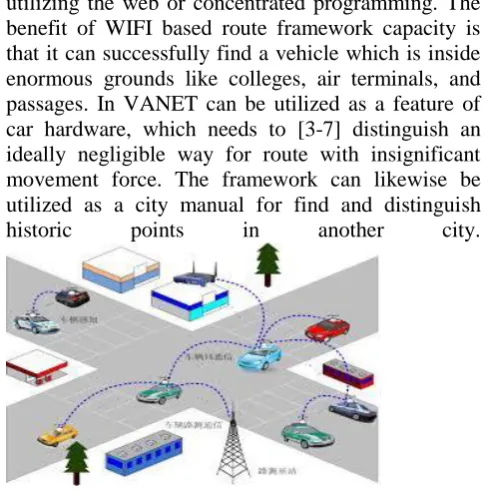
Intelligent vehicular ad hoc networks (inVANETs) use WIFI IEEE802.11p (wave standard) and wimax IEEE802.16 for simple and viable correspondence between vehicles with element versatility. Successful measures, for example, media correspondence between vehicles can be empowered also strategies to track car vehicles.[2],[5] Car vehicular data can be seen on electronic maps
utilizing the web or concentrated programming. The benefit of WIFI based route framework capacity is that it can successfully find a vehicle which is inside enormous grounds like colleges, air terminals, and passages. In VANET can be utilized as a feature of car hardware, which needs to [3-7] distinguish an ideally negligible way for route with insignificant movement force. The framework can likewise be utilized as a city manual for find and distinguish historic points in another city.
International Journal of Inventions in Computer Science and Engineering, Volume 5 Issue 5-7 May-July 2018
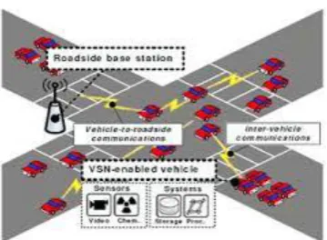
fig 2: vanet with rsu’s
Vehicular ad hoc network (VANET) is an emerging new technology integrating ad hoc network, wireless LAN (WLAN) and cellular technology to achieve intelligent inter-vehicle communications and improve road traffic safety and efficiency. VANETs are distinguished from other kinds of ad hoc networks by their hybrid network architectures, node movement characteristics, and new application scenarios. Therefore, VANETs pose many unique networking research challenges, and the design of an efficient routing protocol for VANETs is very crucial.6
2. Intelligent Transport System
Motivation and Purpose Vehicular accidents have claimed the lives of more Canadians over the past 50 years than the two world wars combined; each day eight Canadians on average die in vehicular collisions. On a global scale, the social and economic impact of road accidents is staggering. The World Health Organization (WHO)[3],[4],[6] and the World Bank estim
ate their direct economic cost at US$ 518 billion. In terms of global burdens of disease and injury, traffic accidents are projected to become the third highest contributor of disability adjusted life years (DALY) by 2020.
A roadmap for the next generation of vehicle safety-enhancing technology is defined under the banner of Intelligent Transportation Systems (ITS), which aim to improve road travel by preventing accidents, managing traffic volume, and streamlining toll collection, etc. A key component of the ITS framework is a vehicular communication network
that provides low-latency and highly-reliable communication amongst vehicles and between vehicles and the roadside infrastructure. The ITS architecture as defined by the U.S. Department of Transportation is illustrated in Fig 1. It is evident that the many envisioned applications and services depend on the viability of the underlying communication platform. [8],[10]Therefore, ITS and safety-enhancing applications in particular have motivated the field of vehicular ad hoc networks (VANET) as a key enabling technology
.
Reference categorizes ITS applications under each of these two types of communication. While V2V applications are mostly safety-related, [9],V2I applications include both safety applications and commercial applications such as electronic toll collection and in-vehicle advertising. These V2I applications require a wireless connection between vehicles and stationary Road Side Units (RSU) deployed along the length of the road.fig 3: U.S. department of transportation its architecture
International Journal of Inventions in Computer Science and Engineering, Volume 5 Issue 5-7 May-July 2018
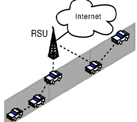
fig 4: use of multi-hop to extend the coverage of an RSU.
2.1intelligent transport innovations
intelligent transport frameworks differ in advances connected, from essential administration frameworks, for example, auto route; activity signal control frameworks; holder administration frameworks; variable message signs; [11],[12]Additionally, prescient methods are being created to permit propelled demonstrating and examination with chronicled benchmark information. Some of these advancements are depicted in the accompanying segments.
2.2 Wireless interchanges
Different types of remote interchanges innovations have been proposed for clever transportation systems.Radio modem correspondence on UHF and VHF frequencies are broadly utilized for short and long range correspondence inside ITS.7
Short-go interchanges of 350 m can be refined utilizing IEEE 802.11 conventions, particularly WAVE or the Dedicated Short Range Communications standard being advanced by the Intelligent Transportation Society of America and the United States Department of Transportation. Hypothetically, the scope of these conventions can be expanded utilizing Mobile specially appointed systems or Mesh organizing.
2.3 Detecting innovations
Mechanical advances in information transfers and data innovation, combined with ultramodern/best in class microchip, RFID (Radio Frequency Identification), and economical wise guide detecting advances, have upgraded the specialized capacities that will encourage driver wellbeing advantages for smart transportation frameworks all inclusive. Detecting frameworks for ITS are vehicle-and foundation based arranged frameworks, i.e., Intelligent vehicle advances. Base sensors are indestructible, [15] (for example, in-street reflectors) gadgets that are introduced or inserted in the street or encompassing the street (e.g., on structures, posts, and signs), as required, and might be physically scattered amid preventive street development upkeep or by sensor infusion hardware for fast organization.8
2.4 Inductive circle discovery
Inductive circles can be set in a roadbed to identify vehicles as they go through the circle's attractive field. The least difficult identifiers essentially check the quantity of vehicles amid a unit of time (ordinarily 60 seconds in the United States) that disregard the circle, while more modern sensors evaluate the pace, length, and class of vehicles and the separation between them. Circles can be put in a solitary path or over various paths, and they work with moderate or ceased vehicles and in addition vehicles moving at fast.
2.5 Video vehicle discovery
International Journal of Inventions in Computer Science and Engineering, Volume 5 Issue 5-7 May-July 2018
2.6 Bluetooth discovery
Bluetooth is an exact and reasonable approach to gauge travel time and make starting point and destination investigation [14]. Bluetooth is a remote standard used to convey between electron dresses from Bluetooth gadgets in passing vehicles. On the off chance that these sensors are interconnected they can compute travel time and give information to root and destination frameworks.9
2.7 Audio recognition
It is additionally conceivable to quantify activity thickness on a street utilizing the Audio flag that comprises of the total sound from tire commotion, motor clamor, motor sitting out of gear commotion, blares and air turbulence commotion. A roadside-introduced mouthpiece grabs the sound that includes the different vehicle clamor and Audio signal handling systems can be utilized to appraise the activity state. The precision of such a framework contrasts well and alternate strategies depicted previously.
3. Movement Planning
Movement arranging (otherwise called the route issue or the piano mover's issue) is a term utilized as a part of mechanical autonomy for the procedure of separating a sought development errand into discrete movements that fulfill development requirements and conceivably enhance some part of the development.
3.1 Concepts
A fundamental movement arranging issue is to deliver a ceaseless movement that interfaces a begin arrangement S and an objective design G, while staying away from crash with known obstructions. The robot and impediment geometry is portrayed in a 2D or 3D workspace, while the movement is spoken to as a way in (potentially higher-dimensional) setup space.10
3.2 Configuration Space
An arrangement depicts the stance of the robot, and the design space C is the arrangement of every single conceivable setup. For instance:
• If the robot is a solitary point (zero-sized) deciphering in a 2-dimensional plane (the workspace), C is a plane, and a design can be spoken to utilizing two parameters (x, y).
• If the robot is a 2D shape that can interpret and turn, the workspace is still 2-dimensional.
• If the robot is a strong 3D shape that can interpret and turn, the workspace is 3-dimensional.
• If the robot is a settled base controller with N revolute joints (and no shut circles), C is N-dimensional.
3.3 Free Space
The arrangement of setups that maintains a strategic distance from crash with snags is known as the free space Cfree. The supplement of Cfree in C is known as the hindrance or illegal region.Often, it is restrictively hard to unequivocally figure the state of Cfree. In any case, testing whether a given setup is in Cfree is effective. To begin with, forward kinematics decide the position of the robot's geometry, and crash recognition tests if the robot's geometry slams into the earth's geometry.
3.4 Completeness and Performance
A movement organizer is said to be finished if the organizer in limited time either creates an answer or accurately reports that there is none. Most finish calculations are geometry-based. The execution of a complete organizer is evaluated by its computational multifaceted nature.
Probabilistic culmination is the property that as more "work" is performed, the likelihood that the organizer neglects to discover a way, on the off chance that one exists, asymptotically approaches zero. A few example based techniques are probabilistically finished. The execution of a probabilistically finish organizer is measured by the rate of meeting.
International Journal of Inventions in Computer Science and Engineering, Volume 5 Issue 5-7 May-July 2018
4. Hybrid Communication
The Vehicular Ad-hoc Network (VANET), a variant of the Mobile Ad-hoc Network (MANET), is a continuously self configuring, infrastructure less network. The Mobile nodes in VANET are vehicle equipped with On-Board Units (OBU), which are wireless communication devices, OBUs used to enable vehicles in VANET to exchange traffic messages with nearby mobile nodes. Communications in VANETs can be divided into two types’ vehicle-to-vehicle communication (V2V) and vehicle-to-infrastructure communication (V2I). Both type of communication are controlled by a short range wireless communication protocol, called the Dedicated Short Range Communication (DSRC) protocol and each vehicles communicate with nearby vehicles and Road Side Units (RSUs) located at roadside can communicate with the traffic control center through the Internet.
4.1 Relay node selection-based cooperative forwarding
This paper presented repetition-based MAC protocols for vehicular broadcast and in particular the RELAY NODE SELECTION-based scheme proposed. However, repetitions within a time frame cannot account for the effects of slow-fading channels and nodes suffering from shadowing effects from obstacles. One well-known method of dealing with these problems is by exploiting spatial diversity and the broadcast nature of wireless transmissions, that is, the independent channel conditions of antennas located at different points in space.
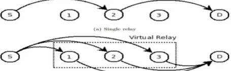
4.2 A simple multi-relay forwarding scheme
To motivate many of the features of the proposed scheme described later in this chapter, let us first consider a naive design of a relay multi-hop forwarding scheme. In designing the routing layer separately from the MAC layer, a naive approach would be to implement a position-based routing scheme such as GPSR or CBF on top of the RELAY NODE SELECTION based MAC. For example, by taking CBF’s approach to opportunistic forwarding, we arrive at a multi-relay forwarding scheme in which a packet’s optimal forwarder is found through contention among the successful receivers of the transmission of the previous hop.
fig 5: transmission queue and synchronous relay node selection-mac for w = 3 and
l = 10.
Each relay will then place its ID and position information in the packet header, update the packet’s hop count, and add w copies of the received packet to its FIFO transmission queue.
4.3 The proposed cooperative forwarding protocol While other multi-relay forwarding schemes exist in literature, the main novel ideas of the scheme proposed in the remainder of this chapter are a) to temporarily assign additional transmission opportunities to the transmission frame of relay nodes; and b) to coordinate the relaying nodes’ transmission times in a structured way, specifically, according to a RELAY NODE SELECTION codeword.
4.4 virtual relays
In order to retain the performance benefits of the RELAY NODE SELECTION-MAC in the multi-hop flows, the channel access times of the multiple relays at each hop should also adhere to a RELAY NODE SELECTION codeword.
fig 6: round-robin time slot assignment for a 3-node virtual relay
International Journal of Inventions in Computer Science and Engineering, Volume 5 Issue 5-7 May-July 2018
network. Finally, the code allocation mechanism forvirtual relays will be described in detail.
4.5 Allocation scheme for relay node selection-MAC A distributed code assignment scheme was proposed and will be summarized briefly. The RELAY NODE SELECTION codebook is divided into a set of “permanent codeword’s” and a smaller set of “temporary or tentative codeword’s” used strictly for network association.
Express the degree of spatial reuse of this scheme by the maximum code density λC, which is the maximum number of codewords per unit length of the road. Given that there are N codewords in the codebook, the code density is λC = N 4R.F.Modified location-based code allocation scheme
Let us consider a vehicular network in a chain topology on a one-dimensional stretch of highway. Begin by dividing the RELAY NODE SELECTION codebook C into three equal subsets which we denote by Ca, Cb, and Cc. The highway is then divided into equal segments or zones of length R, and each zone is associated with one of the three codeword subsets of RELAY NODE SELECTION.
5. Simulation Results
In our proposed method “The Vehicular hoc Network (VANET), a variant of the Mobile Ad-hoc Network (MANET), is a continuously self configuring, infrastructure less network. The Mobile nodes in VANET are vehicle equipped with On-Board Units (OBU), which are wireless communication devices, OBUs used to enable vehicles in VANET to exchange traffic messages with nearby mobile nodes. Communications in VANETs can be divided into two types’ vehicle communication (V2V) and vehicle-to-infrastructure communication (V2I). Both type of communication are controlled by a short range wireless communication protocol, called the Dedicated Short Range Communication (DSRC) protocol and each vehicles communicate with nearby vehicles and Road Side Units (RSUs) located at roadside can communicate with the traffic control center through the Internet”.
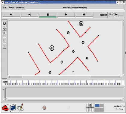
fig 7: formation of nodes
In above figure the multi hop network which has more nodes to placed in a particular location and that are redy to communicate with each other.The reliable RELAY NODE SELECTION-MAC protocol for multi-hop communication. The proposed scheme is cooperative in the sense that forwarding is performed by multiple cooperating relays, thereby exploiting spatial diversity in both the sending and receiving nodes at each hop.
International Journal of Inventions in Computer Science and Engineering, Volume 5 Issue 5-7 May-July 2018
fig 8:RSU’s are identified
fig 9: nodes are ready to communicate with other
The fig 9 shows the RSU is placed in a particular location for a coverage area. For that we are here using two RSU in road side areas. The nearby node in a particular coverage area that passes the information to RSU. A node that successfully receives a packet will first search the list for its packet ID. If not found, the packet’s ID is added to the list. Next, the receiving node will determine its candidacy for becoming a relay using the position information of the destination and the previous hop sender located in the packet header and its own GPS location.The data broadcasting is done to all the nodes through RSU.In RSU all the vehicle’s ID are stored.
fig 10: data broadcasted to all vehicle through RSU
The fig 10 represents the RSU give a request to another node which is in the another coverage area and it treats that node as a active relay node. Each relay will then place its ID and position information in the packet header, update the packet’s hop count, and add w copies of the received packet to its FIFO transmission queue.
fig 11: selection of RSU in a coverage area
International Journal of Inventions in Computer Science and Engineering, Volume 5 Issue 5-7 May-July 2018
fig 12: data is broadcasted to RSU
Fig 12 represents the different node acts as a active relay node to pass the information to neighborhood nodes by using VANET communication system.If we allow each node to transmit not only with its own RELAY NODE SELECTION pattern, but also in designated time slots for forwarding multi-hop traffic which have been assigned to it by the previous hop, each node will be able to transmit with a rate that is greater than that of its RELAY NODE SELECTION (w L).
fig 13:vehicle id is chosen
Figure 8.7 represents the network is connected for the communication.The data broadcasting is done to all the nodes through RSU.In RSU all the vehicle’s ID are stored. Since transmission opportunities are thus allocated per data flow, nodes located at network bottlenecks will automatically obtain more access opportunities to the broadcast channel. Such an approach should be better suited for V2I communications and is the one taken by the proposed forwarding scheme.
fig 14: RSU gets connected with the nodes
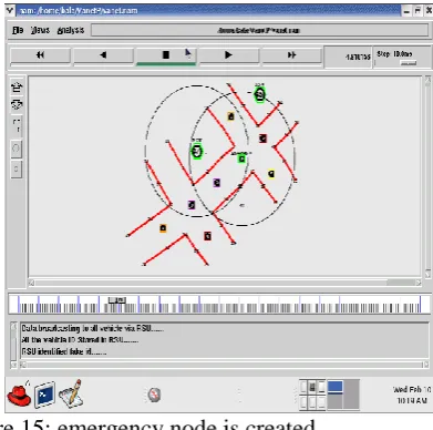
Fig 14 represents the network is connected for the communication.The data broadcasting is done to all the nodes through RSU.In RSU all the vehicle’s ID are stored. While other multi-relay forwarding schemes exist in literature, the main novel ideas of the scheme proposed in the remainder of this chapter are a) to temporarily assign additional transmission opportunities to the transmission frame of relay nodes; and b) to coordinate the relaying nodes’ transmission times in a structured way, specifically, according to a RELAY NODE SELECTION codeword.
figure 15: emergency node is created
International Journal of Inventions in Computer Science and Engineering, Volume 5 Issue 5-7 May-July 2018
based MAC, thereby benefiting from that scheme’srobustness to changes in network topology and the effect of hidden terminals.
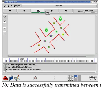
Fig 16: Data is successfully transmitted between the nodes
In Fig 16 represents the emergency vehicle communicate towards target.The nodes changes the mobility apart from accident path. And finally the traffic condition in that area cleared by the implementation of active relay node using intelligent VANET communication system.
6.Conclusion
Thus the process is securing the communication process. Then identify the original user and control the traffic signals. The function of batch verification of multiple messages is included in the proposed ID-based CPPA scheme. The security analysis shows that the proposed scheme can overcome the weaknesses of previously proposed schemes and satisfy the security requirements of ID-based CPPA schemes for VANETs. Our performance analysis results show that the proposed scheme incurs lower computation cost and communication cost because no bilinear pairings are used in our proposed ID-based CPPA scheme.
7. References
[1] TTI, Texas Transportation Institute: urban mobility information, 2007 Annual Urban Mobility Report.
[2] M. Papageorgiou, C. Diakaki, V. Dinopoulou, A. Kotsialos, and Y. Wang, “Review of road traffic control strategies,” Proc. The IEEE, vol. 91, no. 12, pp. 2043-2067, 2003.
[3] T. Hunter, R. Herring, P. Abbeel, and A. Bayen, “Path and travel time inference from GPS probe
vehicle data,” Proc. Neural Information Processing Systems Foundation, Vancouver, Canada, Dec. 2009. [4] H. Hartenstein and K. Laberteaux, VANET: vehicular applications and inter-networking technologies, John Wiley and Sons Publishers, 2010. [5] R. Lu, X. Lin, and X. Shen, “SPRING: A social-based privacy- preserving packet forwarding protocol for vehicular delay tolerant networks,” Proc. IEEE INFOCOM, San Diego, USA, Mar. 2010.
[6] M. Wang, H. Liang, R. Zhang, R. Deng, X. Shen, “Mobility-aware coordinated charging for electric vehicles in VANET-enhanced smart grid,” IEEE Journal Selected Areas of Communications, to appear.
[7] A. Skabardonis and N. Geroliminis, “Real-time monitoring and con- trol on signalized arterials,” IEEE Journal of Intelligent Transporta- tion Systems: Technology, Planning, and Operations, vol. 12, no. 2, pp. 64-74, 2008.
[8] I. Leontiadis, G. Marfia, D. Mack, G. Pau, C. Mascolo, and M. Gerla, “On the effectiveness of an opportunistic traffic management system for vehicular networks,” IEEE Trans. on Intelligent Transportation Systems, vol. 12, no. 4, pp. 1537-1548, 2011.
[9] N. Drawil and O. Basir, “Intervehicle-communication-assisted local- ization,” IEEE Trans. on Intelligent Transportation Systems, vol. 11, no. 3, pp. 678-691, 2010.
[10] Arun Malik , Babita Pandey “Performance Analysis of Various Data Collection Schemes used in VANET”,Indian journal of science and technology, Volume 8, Issue 15, July 2015
[11] MalikSchoch, Elmar, et al. "Communication patterns in VANETs." IEEE Communications Magazine 46.11 (2008): 119-125.
[12] Schoch, E., Kargl, F., Weber, M., & Leinmuller,
T. (2008). Communication patterns in
VANETs. IEEE Communications Magazine, 46(11), 119-125.
[13] Schoch, Elmar, Frank Kargl, Michael Weber, and Tim Leinmuller. "Communication patterns in VANETs." IEEE Communications Magazine 46, no. 11 (2008): 119-125.