Intermodulation Distortion
Swapnil P. Kulkarni Prof. M. R. Madki
Master Student Professor
Department of Electronics Engineering Department of Electronics Engineering
W.I.T.Solapur W.I.T.Solapur
Abstract
Intermodulation distortion (IMD) is a common problem in a variety of areas of electronics. In RF communications in particular it represents a difficult challenge to designers who face tougher requirements on component and sub system linearity. This trend is driven in part, by an increase in radio spectrum congestion. This paper aims to identify the mechanisms responsible for generating intermodulation distortion and to examine some of the methods which may be used to measure and combat the problem. The emphasis is largely directed towards radio communications, yet many of the principles are directly applicable to other fields of application. Where appropriate, examples of real test applications are introduced.
Keywords: Intermodulation distortion (IMD) , Second Order Intercept point(SOI),Third Order Intercept point(TOI), Cognitive radio, software defined radio, nonlinear Distortion, interference cancellation
_______________________________________________________________________________________________________
I. INTRODUCTION
As the second decade of cognitive radio (CR) has begun, research concentrates on real implementations and practical evaluation of the conceived algorithms and concepts. Software defined radios (SDRs) are commercially available and provide ample opportunities for experimental-driven research. However, to meet the requirements of the CR concept, a SDR with a wideband RF front-end is necessary to access many available radio systems. The key issues for these front-ends are dynamic range and linearity. CRs have to sense and communicate under extreme dynamic range conditions with weak signals and strong interferers simultaneously present [1]. In general, these demands for the analogue RF modules and analogue-to-digital converter (ADC) reach still far beyond the state-of-the-art electronics. Now, the CR research community is increasingly addressing practical limitations of the RF hardware.
There are different types of RF imperfections, e.g. mirror frequency interference (I/Q imbalance), non-linear distortions (Intermodulation Distortion), timing jitter, and phase noise [2].
II. WHAT IS ‘IMD’?
Intermodulation distortion is the result of two or more signals interacting in a non linear device to produce additional unwanted signals. These additional signals (intermodulation products) occur mainly in devices such as amplifiers and mixers, but to a lesser extent they also occur in passive devices such as those found in many transmission systems. For example, RF connectors on transmission feeds may become corroded over time resulting in them behaving as non linear diode junctions. The same can apply at the junction of different metals or where magnetic materials are used.
Two interacting signals will produce intermodulation products at the sum and difference of integer multiples of the original frequencies. For two input signals, the output frequency components can be expressed as:
𝑚𝑓1± 𝑛𝑓2
Where , m and n are integers.
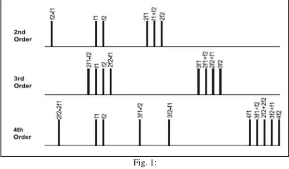
The order of the intermodulation product is the sum of the integers m+n. The ‘two tone’ third order components, (2𝑓1− 𝑓2
and 2𝑓2− 𝑓1) are particularly important because unlike 2nd order distortion, i.e. harmonic distortion at 2𝑓1 or 2𝑓2, they can occur
at frequencies close to the desired/interfering signals and so cannot be easily filtered. Higher order intermodulation products are generally less important because they have lower amplitudes and are more widely spaced. The remaining third order products, 2𝑓1+ 𝑓2 and 2𝑓2+ 𝑓1, do not generally present a problem. The distribution of harmonics and third order products are shown in
Fig. 1:
For example, if two signals, f1 and f2, at 90 MHz and 95 MHz respectively are applied to an amplifier, any non-linearity of the device will result in two tone third order intermodulation products at 85 MHz ((2 x 90) - 95)) and 100 MHz ((2 x 95) - 90), plus two further signals at 275 MHz and 280 MHz, 2nd order harmonics at 180 MHz and 190 MHz and additional 3rd order intermodulation products (or 3rd harmonics) at 270 MHz and 285 MHz It is also possible for second order intermodulation products to be generated at the same frequency as the third order intermodulation products. This is usually because there is already harmonic distortion occurring on the input to the device under test, possibly from the applied test signal. Depending on the phase relationship between the second and third order intermodulation products, this effect may contribute constructively or destructively to the amplitude of the combined intermodulation products. This results in the real two tone third order intermodulation level being either exaggerated or underrepresented respectively. The magnitude of intermodulation products cannot be predicted easily but it is known that their amplitude diminishes with order. Third order intermodulation products have an amplitude proportional to the cube of the input signal whereas second order components have an amplitude proportional to the square of the input signal. Thus if two input signals, equal in magnitude, each rise by1 dB then the third order intermodulation products rise by 3 dB, and the 2nd order components by 2 dB. Higher order terms behave accordingly. However, although 3rd order intermodulation products grow at higher rates, their levels are initially very small compared to lower order components which generally dominate. This RF level dependency leads to a simple test to establish the mechanism responsible for various distortion products, i.e.2nd order or 3rd order effects.
Intermodulation products either side of signal tones may not behave symmetrically. The difference in their level indicates the presence of a more complex mechanism, or in the case of ideally spaced tones it may indicate the effects of frequency response.
Three Tone IM Distortion
Some devices are operated in conditions where a number of inputs may be present, in which case testing should be carried out with multiple outputs .The effect of intermodulation distortion may differ with the introduction of further interfering signals. With three signals present at the input of an amplifier or mixer, three sets of IM products are produced (caused by f1&f2 combining, f1&f3 combining and f2&f3 combining), this is shown in figure 2. A total of 15 different third order products may be generated (including 3rd harmonics) of which 6 are important. For equally spaced tones, 2 of these 6 occur at the same frequency as two of the interfering tones, (C and D in Fig. 2 below). The phase relationship between these intermodulations and the associated interfering signal modifies their combined level. This in turn results in a change in the level of the other intermodulation products generated. A test system assembled for this purpose should allow control of the phase of each signal relative to a common reference, in order that the worse case intermodulation distortion products may be found.
III. REDUCING INTERMODULATION DISTORTION
Fig. 2:
These techniques include : 1) Cartesian loop
2) Feedforward Correction 3) Predistortion
4) Envelope Elimination and Restoration (EE&R)
5) Linear Amplificationusing Nonlinear Components (LINC) / Combined Analog Locked-Loop Universal Modulator (CALLUM).
These techniques for increasing linearity and therefore reducing intermodulation distortion, will be discussed briefly below. Cartesian loop
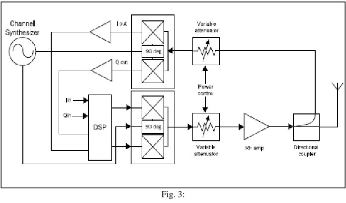
The Cartesian loop technique provides linearisation of a complete transmitter as opposed to just the power amplifier and is shown in Fig. 3.
Fig. 3:
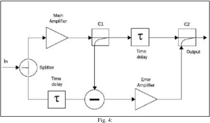
Fig. 4:
The input signal is split to form two identical paths. The signal in the top path is amplified by the main power amplifier. Here, intermodulation, harmonic distortion components and noise are added as a result of the non linearity of the amplifier. The directional coupler takes a sample of the main paths signal and feeds it, 1800out of phase, into the subtractor. In the subtractor a
time delayed portion of the original signal is subtracted from the sample of the main signal to give an error signal. This error signal is linearly amplified to a level where it cancels out the distortion on the time delayed main signal.
This technique may be susceptible to drift in gain and group delay characteristics due to variations in temperature, supply voltage and other variable conditions.
RF Predistortion
Predistortion is conceptually the simplest form of linearization available for an RF power amplifier. Most predistortion systems are based on predistortion of the input system and fall into one of three categories:
RF predistortion IF predistortion Baseband predistortion
The techniques used in RF and IF predistortion are generally similar. Their main advantage is their ability to linearize the entire bandwidth of an amplifier or system simultaneously, therefore making them useful in PCN basestation applications. It is generally used in conjunction with feedforward systems in order to achieve higher degrees of linearity. RF predistortion is a mature technology, with variations such as baseband predistortion proving increasing useful.
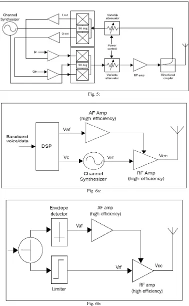
As the name suggests, in this system predistortion is applied at baseband before upconversion to RF. The basic form of the system is shown in Fig. 5. A feedback path is generally provided to support real-time adjustment of the predistortion coefficient in order to maintain a highlevel of linearity. The baseband predistortion method has proved to be less popular than the Cartesian loop approach. This is due to the additional signal processing required and the need for one or more analog-to-digital converters in the feedback path, which greatly add to the overall power consumption. Solutions to the problem of increased power consumption are beginning to appear suggesting that this method may become increasingly popular in the future.
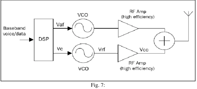
EE&R (Envelope Elimination and Restoration)
The EE&R technique has the advantage that it can be implemented in a number of different ways. Circuits demonstrating the EE&R technique implemented as a linear transmitter and as an amplifier linearization technique are shown in Fig. 6a and Fig. 6b respectively
Fig. 5:
Fig. 6a:
Fig. 7:
The modulating signal is generated in the digital signal processor as two constant envelope phase modulated signals. After upconversion and amplification, these two signals will add to produce the required linear output signal. In order to reduce the intermodulation distortion unwanted signals must be screened and device linearity must be improved.
IV. CONCLUSION
Intermodulation distortion has a debilitating effect on the performance of telecommunications networks. The resulting decreased system capacity and degraded call quality at cell sites results in reduced revenue for the wireless service provider. Controlling the generation of intermodulation is key to maintaining capacity and service quality. Likewise, receivers need to have minimised intermodulation distortion in order to maintain call quality; an increasingly difficult task in todays increasingly congested networks.
REFERENCES
[1] M. Allen, J. Marttila, and M. Valkama, “Digitally-enhanced wideband analog-digital interfaces for future cognitive radio devices,” in NEWCAS
Conference (NEWCAS), 2010 8th IEEE International, June 2010, pp.
[2] 361–364.
[3] M. Valkama, A. Springer, and G. Hueber, “Digital signal processing for reducing the effects of RF imperfections in radio devices - an overview,” Circuits
and Systems (ISCAS), Proceedings of 2010 IEEE International Symposium on, pp. 813–816, June 2010.
[4] G. Fettweis, M. Lohning, D. Petrovic, M. Windisch, P. Zillmann, and W. Rave, “Dirty RF: a new paradigm,” Personal, Indoor and Mobile Radio
Communications, 2005. PIMRC 2005. IEEE 16th International Symposium on, vol. 4, pp. 2347–2355, Sept. 2005.
[5] M. Valkama, A. Shahed Hagh Ghadam, L. Anttila, and M. Renfors, “Advanced digital signal processing techniques for compensation of nonlinear
distortion in wideband multicarrier radio receivers,” Microwave Theory and Techniques, IEEE Transactions on, vol. 54, no. 6, pp. 2356–2366, June 2006.
[6] Q. Zou, M. Mikhemar, and A. Sayed, “Digital compensation of cross modulation distortion in software-defined radios,” Selected Topics in Signal
Processing, IEEE Journal of, vol. 3, pp. 348–361, June 2009.
[7] E. Keehr and A. Hajimiri, “Digitally-assisted linearization of wideband direct conversion receivers,” European Microwave Integrated Circuit Conference,
EuMIC, pp. 159–162, Oct. 2008.
[8] Y. Chiu, “Equalization techniques for nonlinear analog circuits,” Communications Magazine, IEEE, vol. 49, no. 4, pp. 132–139, April 2011.
[9] M. Oude Alink, E. Klumperink, M. Soer, A. Kokkeler, and B. Nauta, “A 50MHz-to-1.5GHz cross-correlation CMOS spectrum analyzer for cognitive radio
with 89dB SFDR in 1MHz RBW,” in New Frontiers in Dynamic Spectrum, 2010 IEEE Symposium on, April 2010, pp. 1–6.
[10] M. Grimm, R. K. Sharma, M. Hein, and R. Thoma, “Mitigation of non-linearly induced interference in cognitive wideband receivers,” 7th Workshop on
Software Radios, Karlsruhe, Germany, March 2012.
[11] P. B. Kenington, High-linearity RF amplifier design. Boston, Mass. [u.a.]: Artech House, 2000.
[12] M. Grimm, A. Krah, N. Murtaza, R. K. Sharma, M. Landmann, R. Thoma, A. Heuberger, and M. Hein, “Performance evaluation of directional spectrum
sensing using an over-the-air testbed,” 4th International Conference on Cognitive Radio and Advanced Spectrum Management, CogART’11, Barcelona, Spain, Oct. 2011.