OPTIMIZATION OF PROCESS
PARAMETERS FOR CNC EDM ON
OHNS TOOL STEEL USING
DESIRABILITY FUNCTION
TSRV Padmalatha
Department of Mechanical Engineering, University College of Engineering, Osmania University, Hyderabad, Telangana 500 007, India
T NAGAVENI
Department of Mechanical Engineering, University College of Engineering, Osmania University, Hyderabad, Telangana 500 007, India
*K.Saraswathamma
Department of Mechanical Engineering, University College of Engineering, Osmania University, Hyderabad, Telangana 500 007, India
[email protected] Abstract
Electrical Discharge Machining (EDM) is well-established unconventional machining and able to machine complex geometries as well as difficult-to-machine materials such as super alloys, carbides, heat treated tool steels, composites, heat resistant steels etc. Present paper is focused on the detailed study and optimization of machining parameters of EDM on response variables using reverse polarity. Experiments were designed and conducted using Central Composite Rotatable Design (CCRD) involving three input factors with five levels. Separate Analysis of Variance (ANOVA) for MRR and TWR were conducted and contribution of each parameter affecting the improvement in MRR and TWR was done through regression equation. Investigation results indicates that MRR and TWR increases with an increase in the current and Ton. Multi response optimization was conducted for maximum MRR and minimum TWR and optimization values are 8.28A (current), 60 µs (Ton) and 10µs (Toff).
Key words: CNC EDM, OHNS tool steel, Pulse current, Ton, Toff, MRR, TWR, reverse polarity.
1. Introduction
Electrical discharge machining (EDM) is one of the widely used non-conventional material removal processes and has replaced most of the conventional machining operations. EDM is now a good machining option in the manufacturing and Production industry mainly in the manufacture of mould, die, and automotive, aerospace and surgical components due to its unique advantages. Electro Discharge Machining (EDM) utilizes electrical energy to generate electrical sparks and removal of material takes place mainly due to liberated thermal energy of the spark (Jain 2009).
melting and partly vaporization. The workpiece top surface which is exposed re-solidifies and consequently cools very quickly. Although the metal removal is due to thermal effect, but there is no heating of bulk material.
The properties of good hardness and machinability of Oil-hardened tool steel (OHNS) makes it economical in making cutting and blanking tools and gauging tools .Applications of tool steels are Blanking and stamping dies, Punches, Rotary shear blades, Thread cutting tools, Milling cutters, Reamers, Measuring tools, Gauging tools, Wood working tools, Broaches, Chasers. Due to their high strength and toughness they are categorized as difficult to machine materials, which throw challenges both in traditional and non-traditional machining processes.
Kiyak, et al. (Kiyak and Çakır 2007) explored the effect of machining parameters on surface roughness of AISI P20 tool steel which is widely used in the plastic mold and die making. Results of their work shows that surface finish and machining outputs were increased with an increase in the current. Haddad et al. (Haddad and Tehrani 2008) carried out MRR, surface roughness (Ra), and roundness study using cylindrical wire electrical discharge turning (WEDT) on AISI D3 tool steel by varying power, voltage, pulse off time, and spindle rotational speed. From the results, they concluded that power or voltage has significant effect on the changes in roughness value and MRR which are increased with increase power or voltage. Kapoor et al. (Kumar, Singh et al. 2009) presented a review on surface modification by EDM which is novel application and added a new dimension to the conventional EDM. In surface modification, substantial quantity of material is transferred from the powder suspended dielectric fluid to the machined surface under suitable machining conditions which modifies the surface composition and its properties. Klocke et al. (Klocke, Schwade et al. 2013) investigated the specific wear behaviour and MRR with different grades of graphite electrode in detail and linked to the physical characteristics of the graphite material. To reduce the tool wear in EDM, Yin et al. (Yin, Wang et al. 2014) investigated a new method simultaneous EDM and ECM (SEDCM). Marashi et al. (Marashi, Jafarlou et al. 2016)done review on powder mixed dielectric in EDM and made some of the following observations. Hydrocarbon dielectrics are still most efficient dielectrics used in PMEDM, but, in recent years water and gas dielectrics applications improved (Marashi, Jafarlou et al. 2016). If in dielectrics additive powders are used the discharge characteristics hugely differ in terms of induced energy intensity, spark frequency, discharge gap and spark size(Marashi, Jafarlou et al. 2016). Investigations study by Shankar et al. indicates that, copper and aluminium electrodes give good machining rates when compared to the copper tungsten, and brass electrodes on EN-31 (Singh, Maheshwari et al. 2004).
Many researchers have done experimental work on EDM of tool steel to find material removal rate and tool wear rate. From literature review, it was observed that very few work has been reported on optimization of machining parameters on oil hardened non- shrinkable tool steel (OHNS) with reverse polarity. Hence, the present work is focused to study and optimize the effect of individual machining parameters such as pulse current, pulse-on- time (Ton) and pulse-pause-time (Toff) on material removal rate (MRR) and tool wear rate (TWR) in electric discharge machining of OHNS tool steel with copper electrode.
2. Experimentation
Experiments were carried out on CNC EDM CREATOR CR-6C (die-sinking type) with servo-head (constant gap) and reverse polarity (shown in Fig.1). Commercial grade Kerosene oil was used as a dielectric fluid. Experiments were conducted as per the experimental plan in random order to eliminate experimental errors (shown in Table 2). Workpiece is prepared by setting the weight maximum as 150 gm. The work pieces were prepared by cutting them into the size of 15 mm ×40 mm ×16 mm and then grounded in order to get good surface finish. Circular copper rod of 12 mm diameter and 100 mm length was taken as an electrode and the facing operation was done on lathe in order to get the good surface finish on the faces of the rod. Each workpiece and tool was weighted and recorded before and after machining. Before machining, EDM tank is filled with kerosene and each work piece was machined for 20 min and all experiments carried out according to the experimental plan shown in Table.2. Difference of weight with respect to time before and after machining indicates the MRR on work piece and TWR on electrode respectively and is expressed as
Fig. 1 CNC EDM CREATOR CR-6C die sinking EDM
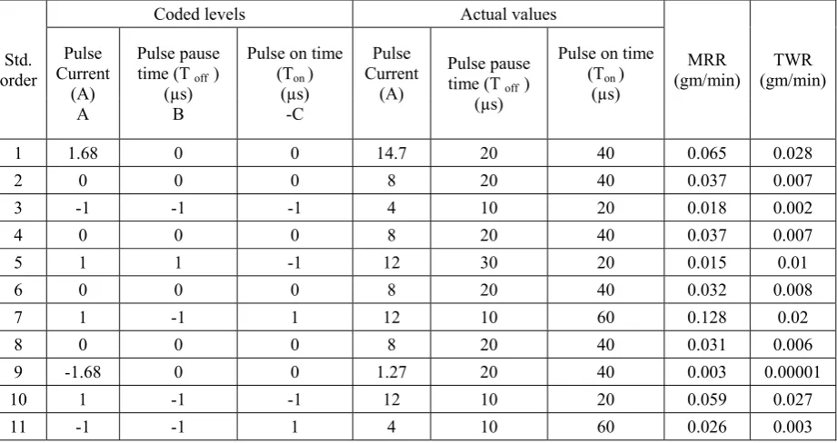
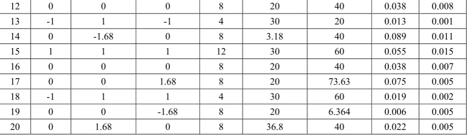
Central composite rotatable design is a full factorial design with central runs and axial runs was used to conduct the experimentation (Montgomery 1997). Two level full factorial designs with six central runs and six axial runs of CCRD was used in this experimentation. Coded and actual values of machining parameters that are used in ED machining of OHNS tool steel is shown in Table 1. The experimental plan and results summary is given in Table 2.
Table 1. Process parameters coded levels and actual values
Machining parameters units Levels
-1.682 -1 0 +1 +1.682 Pulse
Current (A) A 2 4 8 12 15
Pulse pause time
(T off ) (B) µs 3 10 20 30 37 Pulse duration
(Ton ) (C) µs 7 20 40 60 74
Table 2. Experimental plan and results summary
Std. order
Coded levels Actual values
MRR
(gm/min) (gm/min) TWR Pulse
Current (A)
A
Pulse pause time (T off )
(µs) B
Pulse on time (Ton )
(µs) -C
Pulse Current
(A)
Pulse pause time (T off )
(µs)
Pulse on time (Ton )
(µs)
1 1.68 0 0 14.7 20 40 0.065 0.028
2 0 0 0 8 20 40 0.037 0.007
3 -1 -1 -1 4 10 20 0.018 0.002
4 0 0 0 8 20 40 0.037 0.007
5 1 1 -1 12 30 20 0.015 0.01
6 0 0 0 8 20 40 0.032 0.008
7 1 -1 1 12 10 60 0.128 0.02
8 0 0 0 8 20 40 0.031 0.006
9 -1.68 0 0 1.27 20 40 0.003 0.00001
10 1 -1 -1 12 10 20 0.059 0.027
12 0 0 0 8 20 40 0.038 0.008
13 -1 1 -1 4 30 20 0.013 0.001
14 0 -1.68 0 8 3.18 40 0.089 0.011
15 1 1 1 12 30 60 0.055 0.015
16 0 0 0 8 20 40 0.038 0.007
17 0 0 1.68 8 20 73.63 0.075 0.005
18 -1 1 1 4 30 60 0.019 0.002
19 0 0 -1.68 8 20 6.364 0.006 0.005
20 0 1.68 0 8 36.8 40 0.022 0.005
3. RSM Analysis
Analysis of Variance (ANOVA) was conducted separately for MRR and TWR and regression equations were developed to get relationship between responses and machining parameters. The contribution of each parameter of the model, in affecting the improvement in MRR and decrement in TWR was found out through the sum of squares method. It gives the main effect of process parameter on response parameters and these analyses help in design a regression equation for MRR which helps on calculating the MRR. Thus the relationship between input and output parameters is obtained through empirical expressions developed by using the output values of MRR. Analysis was carried out using Stat-Ease Design-Expert® software.
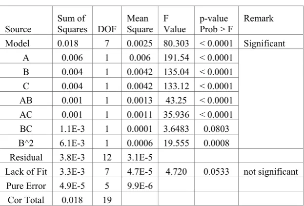
Quadratic model was selected for MRR and TWR from the Lack of fit test. After dropping insignificant model terms, the reduced model of ANOVA for MRR and TWR is shown in Tables 3 & 4 respectively. Value of Prob>F” less than 0.1 indicates model terms are significant. Depending on coefficients calculated, the final regression equations for MRR and TWR is presented below in terms actual values
=
0.00082 + 0.0058 − 0.00099 + 0.000066 − 0.00033 × + 0.00015( ×
) − 0.00002( × ) + 0.000065 --- (2)
( ) = −7.826 + 0.500 − 0.043 + 0.019 − 0.00106 ( × ) + 0.0004 ×
− 0.0115 − 0.00015 --- (3)
Table 3. ANOVA for Tool Wear Rate
Source Squares DOF Sum of Square Mean Value F p-value Prob > F Remark Model 18.37 7 2.62 244.54 < 0.0001 Significant
A 16.45 1 16.45 1532.9 < 0.0001 B 1.04 1 1.046 97.42 < 0.0001 C 0.25 1 0.25 23.49 0.0004 AC 0.057 1 0.06 5.3373 0.0395 BC 0.048 1 0.04 4.55 0.0543 A2 0.490 1 0.49 45.65 < 0.0001 C2 0.049 1 0.05 4.60 0.0530 Residual 0.12 12 0.01
Lack of Fit 0.112 7 0.02 4.85 0.0505 not significant Pure Error 0.016 5 0.003
Table 4. ANOVA for Material Removal Rate
Source Sum of Squares DOF Mean Square F Value p-value Prob > F Remark Model 0.018 7 0.0025 80.303 < 0.0001 Significant
A 0.006 1 0.006 191.54 < 0.0001 B 0.004 1 0.0042 135.04 < 0.0001 C 0.004 1 0.0042 133.12 < 0.0001 AB 0.001 1 0.0013 43.25 < 0.0001 AC 0.001 1 0.0011 35.936 < 0.0001 BC 1.1E-3 1 0.0001 3.6483 0.0803 B^2 6.1E-3 1 0.0006 19.555 0.0008 Residual 3.8E-3 12 3.1E-5
Lack of Fit 3.3E-3 7 4.7E-5 4.720 0.0533 not significant Pure Error 4.9E-5 5 9.9E-6
Cor Total 0.018 19
4. Results and Discussion
4.1 Effect of Pulse current on MRR and TWR
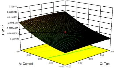
Current is the most imporatnt macining parameter in EDM and ANOVA (shown in Table 3) also highlighting the same. It is evident from the Fig.2 and Fig. 3 that MRR and TWR increases with an increase in the pulse current. As a result, spark energy is increased which will accelerate the action of melting and vaporization, and proceeding the large impulsive force in the spark gap, thereby increasing the MRR and TWR. Higher currents improves the MRR, but at the same time surface roughness and tool wear also increases.
From the interaction plots as shown in Figs.4 &5, it was observed that MRR and TWR increases with an increase in the amount of discharge current and pulse duration, and also increases gas bubbles in the discharge zone. High pulse current and pulse on time also increases surface roughness due to more craters (Kiyak and Çakır 2007).
Fig. 2. Effect of current on MRR Fig. 3. Effect of Pulse current on TWR 0
0.02 0.04 0.06 0.08 0.1
4 6 8 10 12
M
R
R
(g
m/mi
n)
Pulse current (A) Ton 20 µs
Ton 40 µs Ton 60 µs
0 0.01 0.02 0.03 0.04 0.05
4 6 8 10 12
TW
R
(g
m/
mi
n)
Fig.4. Interaction effect of current and Ton on MRR Fig. 5. Interaction effect of current and Ton on TWR
4.2 Effect of pulse pause time (Toff) on MRR and TWR
From the Figs.6 & 7, it is evident that increasing in pulse pause time decreases the MRR and TWR. If increase in pulse pause time the spark contact time with work piece and tool is decreases and hence MRR and TWR will decreases. Due to more time gap in between the successive spark will leads to less amount of material removal. At lower pulse currents even an increase in the pulse pause time, there is no significant effect on both MRR & TWR. But as pulse current increase, the rate of decrease also more.
Fig. 6. Effect of Pulse pause time on TWR Fig. 7. Effect of Pulse pause time on MRR
4.3 Effect of Pulse on time (Ton) on MRR and TWR
Plasma channel discharge energy and the time to transfer this energy into electrode increases with increasing pulse From The Fig. 8, it was perceived that, MRR and TWR increases with increase in the pulse on time, but the rate of increase in TWR is less. Plasma channel discharge energy and the time to transfer this energy in to the electrode increases with increasing pulse on time. This leads to the increase in MRR due to huge molten material crater that is formed on workpiece. When pulse on time alone increases, TWR also increases, but decreases with increse in pulse pause time.
Fig. 8. Effect of pulse on time on MRR Fig.9 Effect of pulse on time on TWR 0
0.05 0.1 0.15 0.2
10 15 20 25 30
M R R (g m/ mi n)
Pulse pause time ( µs) current 12 µs current 8 µs current 4 µs
0 0.04 0.08 0.12 0.16 0.2
20 30 40 50 60
M R R (g m/ mi n)
Pulse on time (µs) Toff 30 µs
Toff 20 µs Toff 10 µs
0 0.01 0.02 0.03
20 30 40 50 60
TW R (g m/ mi n)
Pulse on time (µs)
Toff 30 µs Toff 20 µs Toff 10 µs 0
0.01 0.02 0.03 0.04
10 15 20 25 30
TWR (g m /m in )
Pulse pause time ( µs)
5. Optimization study
Optimization is carried out in terms of desirability function (di) (Sidpara and Jain 2012). For optimization of several response processes widely used methods in industry one of the method is Desirability function approach. It is based on the idea that the "quality" of a product or process which has several quality parameters, even if one of them is outside “desirable" limits, it is considered as totally rejectable. The approach is used to identify process parameters x which provide “most desirable” responses.
Each estimated response variable Ri can be converted to desirability value di, by using desirability function where 0≤ di≤1. With desirability increase the value of di increases. Using geometrical mean, the individual desirability’s are combined in to an equation. This combined response represents the overall desirability assement, that is given by single value of D. In the present case, Material removal rate (MRR) and Tool wear rate (TWR) are the response variables.
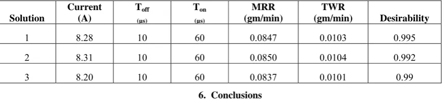
In this case r=1 is selected to consider desirability linear increment. The objective of this optimization study is to maximize MRR (R1) and minimum TWR (R2) which are opposite to each other. The optimum level of independent parameters I found by Design-Expert® Software. The maximum value of D is found by the program search through the level of independent parameters. Table: 5 show the initial three results of the optimization solution for maximizing MRR and minimizing TWR.
Table 5.Results of the optimization study
Solution
Current (A)
Toff (µs)
Ton (µs)
MRR (gm/min)
TWR
(gm/min) Desirability
1 8.28 10 60 0.0847 0.0103 0.995
2 8.31 10 60 0.0850 0.0104 0.992
3 8.20 10 60 0.0837 0.0101 0.99
6. Conclusions
The effect Pulse current, Pulse on time and pulse pause time of EDM on MRR and TWR of OHNS tool steel workpiece and copper electrode with reverse polarity was investigated in the present work. Response surface regression equations were found and presented as Eqs.3-6. The main conclusions are drawn from the experimental study are
• The increase in pulse current leads to a sharp increase in the material removal rate. And also it was observed that, tool wear rate are also increases with increasing the current. So, current was the most significant factor in both MRR and TWR.
• The increase in pulse on time leads to an increase in material removal rate and there is slight increase was observed with respect to the tool wear rate.
• From the optimization study, it was found 8.28A current, 10µs Pulse pause time and 60 µs Pulse on time (are the optimum values to maximize the material removal rate and minimize the tool wear rate.
References
[1] Haddad, M. J. and A. F. Tehrani (2008). "Investigation of cylindrical wire electrical discharge turning (CWEDT) of AISI D3 tool steel based on statistical analysis." Journal of Materials Processing Technology 198(1–3): 77-85.
[2] Jain, V. K. (2009). Advanced machining processes, Allied Publishers.
[3] Kiyak, M. and O. Çakır (2007). "Examination of machining parameters on surface roughness in EDM of tool steel." Journal of Materials Processing Technology 191(1–3): 141-144.
[4] Klocke, F., M. Schwade, A. Klink and D. Veselovac (2013). "Analysis of Material Removal Rate and Electrode Wear in Sinking EDM Roughing Strategies using Different Graphite Grades." Procedia CIRP 6(0): 163-167.
[5] Kumar, S., R. Singh, T. P. Singh and B. L. Sethi (2009). "Surface modification by electrical discharge machining: A review." Journal of Materials Processing Technology 209(8): 3675-3687.
[6] Marashi, H., D. M. Jafarlou, A. A. D. Sarhan and M. Hamdi (2016). "State of the art in powder mixed dielectric for EDM applications." Precision Engineering 46: 11-33.
[7] Montgomery, D. C. (1997). Design and analysis of experiments, Wiley New York.
[8] Sidpara, A. and V. K. Jain (2012). "Nano–level finishing of single crystal silicon blank using magnetorheological finishing process." Tribology International 47(0): 159-166.
[9] Singh, S., S. Maheshwari and P. C. Pandey (2004). "Some investigations into the electric discharge machining of hardened tool steel using different electrode materials." Journal of Materials Processing Technology 149(1–3): 272-277.