AN EFFICIENT ALGORITHM FOR THE REMOVAL
OF IMPULSE NOISE IN IMAGES USING BLACKFIN
PROCESSOR
S. Preethi
1, Ms. K. Subhashini
21
M.E/Embedded System Technologies,
2Assistant professor
Sri Sai Ram Engineering College, Chennai (India)
ABSTRACT
In an image transmission process, there are a lot of noises which are usually divided into three groups:
Gaussian noise, balanced noise and impulse noise. Impulse noise displays as random white or black dots on an
image. It corrupts the image and seriously affects the visual effects. Therefore, the impulse noise reduction has
important significance to image processing. For the images corrupted by impulse noise an imperative
requirement is to remove the noise impulses without disturbing the edges. The linear filtering techniques are
not a proper choice in removing impulse noise. Instead non-linear signal processing techniques such as
median filtering should be involved. Median filters have the capability to remove impulse noise as well as
preserve the edges. At high noise densities it exhibits blurring and insufficient noise suppression. The median
filters operate uniformly across the image and therefore they modify both noise and noise free pixels. Applying
median filter unconditionally across the entire image would inevitably alter the intensities and remove the
signal details of uncorrupted pixels. To overcome all these drawbacks of median filter an efficient removal
impulse noise algorithm is presented for restoration of images that are highly corrupted. This algorithm has
much better image quality than a median filter. It removes only corrupted pixel by the median value or by its
neighboring pixel value.
Keywords: Impulse noise, Median filter, Dual core. Image restoration, Impulse detection, FEINR
I INTRODUCTION
The images corrupted by impulse noise are often occurred in practice. This type of noise may occur in digital images because of channel decoder damages, dyeing down of signals in communication links, communication subscriber’s moving, video sensors noise and other. The impulse noise called salt and pepper causes white and
black points appear in digital and gray scale images, which chaotically scattered along image area. Applying of classic median filter for removal of such type of noise gives relatively good results, which are shown in restoring of brightness drops, objects edges and local peaks in noise corrupted images. But analysis of different sources dedicated to median filtering shows that the classic median filter has a set of disadvantages
For the images corrupted by impulse noise an imperative requirement is to remove the noise impulses without disturbing the edges. Image processing filters require two major characteristics: sufficient noise reduction and preserving the image edges. Ideally, the filtering should be applied only to corrupted pixels while leaving uncorrupted pixels. Applying median filter unconditionally across the entire image would inevitably alter the intensities and remove the signal details of uncorrupted pixels.
A noise-detection process to discriminate between uncorrupted pixels and the corrupted pixels prior to applying nonlinear filtering is required. Some algorithms for this issue (adaptive median filter, decision based or switching median filters) have been proposed. Possible noisy pixels are identified and replaced by using median value or its variant while leaving uncorrupted pixels unchanged.
These median filters are good at lower noise density levels. The number of replacements of corrupted pixel increases in case of higher noise density. On the other hand, defining a robust decision measure is difficult, because the decision is usually based on a predefined threshold value. If the noisy pixels are replaced by some median value in their vicinity without taking into account the possible presence of edges they are not recovered satisfactorily.
All these drawbacks can be overcome by involving two phases: At first an adaptive median filter is applied for classifying corrupted and uncorrupted pixels; In the second phase a specialized method is applied to the noisy pixels to preserve the edges and noise suppression. But for these algorithms the processing time is very high. These entire drawbacks can be rectified by the proposed method. The corrupted pixels are replaced by either the median pixel or neighborhood pixel in contrast to other existing algorithms that use only median values for replacement of corrupted pixels. During higher noise densities, the median value may also be a noisy pixel in which case neighborhood pixels are used for replacement; this provides higher correlation between the corrupted pixel and neighborhood pixel. Higher correlation gives rise to better edge preservation. In addition, this algorithm named fast and efficient impulse noise removal (FEINR) uses simple fixed length window of size 3 x 3, and hence, it requires significantly lower processing time compared with other algorithms.
II SYSTEM DESIGN
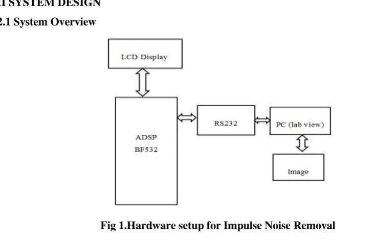
Fig 1 shows the hardware setup for impulse noise removal which is comprised of ADSP BF532 processor, LCD Display, RS232, and a PC for image display. The noisy image is first converted into string using the Labview software before applying it to the processor. Then the converted string is given to the ADSP processor which is loaded with the noise removal algorithm. Here the noise in the image gets removed and it is sent back to the Labview where the string is again converted into image and it is viewed on the display screen.
2.2 Noise Removal Algorithm
In case of median filtering each pixel isreplaced by the median of its neighborhood values in the current analysis window. The FEINR first detect the impulse noise and then replaces the corrupted pixel. The detection of noisy pixels is decided by checking whether the value of a current pixel lies between the maximum and minimum values that occur inside the selected window. The impulse noise pixels can take the maximum value 255 and minimum values 0. If the value of the pixel processed is within the range, then it is an uncorrupted pixel and left unchanged. If the value does not lie within this range, then it is a noisy pixel and is replaced by the median value of the window. If the noise density is high, there is a possibility that the median value is also a noise value. In the latter case, the pixel processed is replaced by the previously processed adjacent neighborhood pixel value in place of the median value. The FEINR is described below:
1) A two dimensional window, W, of size N x N is selected. We note the pixel to be processed as W(x, y). The parameter N was chosen to be 3.
2) The pixel values inside the window are sorted as follows:
2.1. The minimum value of the elements in the W(x, y) - noted by MIN - is computed. 2.2. The maximum value of the elements in the W(x, y) - noted by MAX - is computed. 2.3. The media value of the elements in the W(x, y) - noted by MED - is computed. 3) In this step the noisy pixel are detected as follows:
- if ((MIN < W(x, y) < MAX) and (MIN>0) and (MAX<255)) then the current pixel W (x, y) is a noise free pixel and it is left unchanged else
- if ((MIN <MED< MAX and (0< MED<255)) then the current pixel is a noisy pixel and it will be replaced by MED.
- if (MED= 0) or (MED=255)) then the median value of the current window is a noisy pixel and the current pixel will be replaced by W(x-1, y) (the left neighborhood of current pixel in the window).
4) Steps 1 to 3 are repeated for the entire image.
2.3 ADSP Processor Implementation
The ADSP-BF532 processor is a high performance member of the Blackfin family of products targeting a variety of multimedia, industrial, and telecommunications applications. These Blackfin processors combine a dual-MAC state of the art signal processing engine, the advantage of a clean, orthogonal RISC-like microprocessor instruction set, and single instruction, multiple data (SIMD) multimedia capabilities in a single instruction set architecture. The ADSP-BF532 processor has 328K bytes of on-chip memory.
Fig2. Functional Block Diagram
Each Blackfin core includes: • 16K bytes of instruction SRAM/cache • 16K bytes of instruction SRAM • 32K
bytes of data SRAM/cache • 32K bytes of data SRAM • 4K bytes of scratchpad SRAM Additional on-chip memory peripherals include: • 128K bytes of low latency on-chip L2 SRAM • Four-channel internal memory DMA controller • External memory controller with glue less support for SDRAM, mobile SDRAM, SRAM, and
flash.
Each core functions independently: they have their own reset address, Event Vector Table, instruction and data caches, and so on. On reset, core A starts running from its reset address, while core B is disabled. Core B starts running when it is enabled by core A. When core B starts running, it starts running its own application, from its own reset address. Having one application per core the full potential of the dual core Blackfin processor is exploiting. Effectively, two single-core applications are building independently, and run in parallel on the processor. The shared memory areas, both internal and external, are each sub-divided into three areas–a section dedicated to core A, a section dedicated to core B, and a shared section. It is left up to the developer to arrange for shared, serialized access to the shared areas from each of the cores.
The Blackfin processor instruction set is optimized so that 16-bit opcodes represent the most frequently used instructions. Complex DSP instructions are encoded into 32-bit opcodes as multifunction instructions. Blackfin products support a limited multi issue capability, where a 32-bit instruction can be issued in parallel with two 16-bit instructions. This allows the programmer to use many of the core resources in a single instruction cycle. The Blackfin architecture supports instructions that control vector operations. We take advantage of these instructions to perform simultaneous operations on multiple 16-bit values, including add, subtract, multiply, shift, negate, pack, and search.
The vector search instruction is used in a loop to locate a maximum or minimum element in an array of 16-bit packed data. A condition code GE (greater or equal) or LE (less or equal) will be set in the instruction in order to compute the maximum or the minimum value of the vector. Two values are tested at a time. The vector search instruction compares two 16-bit, signed half-words to values stored in the registers of the Blackfin microcontroller. Then, it conditionally updates each register with minimum or maximum of these values. Also, destination pointers are updated based on the comparison, to indicate the position of minimum and maximum in the vector. The above mention instruction may be used in order to find the MIN, MAX and MED values in a given vector W.
The algorithm is the following:
1) Given the vector W of length N = 2M+1 we find the first two maximum values using the vector search instruction with condition code GE.
2) Compare the two maximum values and set the greater of them as MAX value.
3) Discard the two maximum values computed in step 1) and find two minimum values in the remaining vector of length N-2, using vector search instruction with condition code LE.
4) Compare the two maximum values and set the smaller of them as MIN value.
5) Discard the two minimum values computed previously and find two minimum values in the remaining vector, using vector search instruction with condition code LE.
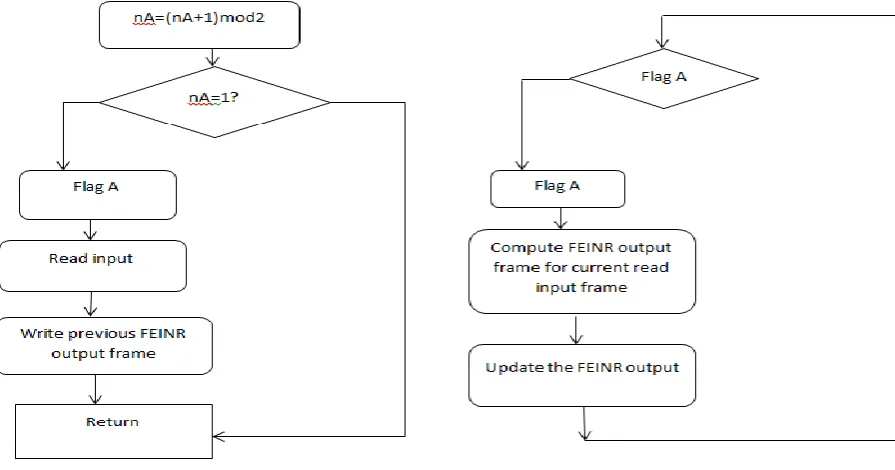
Fig 3.a. Flowchart for core A
Fig 3.b.Flowchart for core B
(flag_A or flag_B) is set to 1. These flags are set in the interrupt service routines for core A or core B. The main programs process the odd or the even input frames only. A necessarily functioning condition is that T_FEINR <2T. The computational effort has been estimated. Also, the median filter length will be chosen as 3 x 3 or 5 x 5. These experiments try to estimate how large a processed image may be if we consider that the image processing system has as input video streams at 30 frames per second. The figures 16 and 17 illustrate the computational effort versus image length (we consider an N pixels x N pixels image, where N represents the parameter in the abscise of the graphs in these figures).
2.4 Image Comparison
30% Noise added image
70% Noise added image
III CONCLUSION
An efficient filtering algorithm for impulsive noise removal is presented. This algorithm has significant better performance in terms of noise removal and edge preservation. A fast sorting method, based on vector search instruction of Blackfin microcomputer, is also illustrated. The overall computation time is significantly reduced if such sorting method is used and if a switched buffer technique is involved based on dual core architecture of the Blackfin microcomputer.
REFERENCES
[2] T. Sun and Y. Neuvo, ―Detail-preserving median based filters in image processing,‖ Pattern Recognit. Lett., vol. 15, pp. 341–347, 1994.
[3] S. Zhang and M. A. Karim, ―A new impulse detector for switching median filters,‖ IEEE Signal Process.
Lett., vol. 9, no. 11, pp. 360–363, Nov. 2002.
[4] ADSP-BF53x/BF56x Blackfin Processor Programming Reference, 2007
[5] Z. Wang and D. Zhang, ―Progressive switching median filter for the removal of impulse noise from highly corrupted images,‖ IEEE Trans. Circuits System II, Analog Digit. Signal Processing, vol. 46, no. 1, pp. 78–
80, Jan. 1999.
[6] Eduardo Abreu, ‖A new efficient approach for the removal of impulse noise from highly corrupted images,‖
IEEE Transactions on Image Processing.Vol. 5, No.6, June 1996.
[7]TZU-CHAOLIN AND PAO-TA Yu,‖ Salt-Pepper impulse noise detection and removal using multiple thresholds for image restoration,‖ Journal of Information Science and Engineering 22,189-198 (2006).