Sun Microsystems, Inc. www.sun.com
Sun Fire
™
T2000 Server
Administration Guide
Copyright 2007 Sun Microsystems, Inc., 4150 Network Circle, Santa Clara, California 95054, U.S.A. All rights reserved.
Sun Microsystems, Inc. has intellectual property rights relating to technology that is described in this document. In particular, and without limitation, these intellectual property rights may include one or more of the U.S. patents listed at http://www.sun.com/patents and one or more additional patents or pending patent applications in the U.S. and in other countries.
This document and the product to which it pertains are distributed under licenses restricting their use, copying, distribution, and
decompilation. No part of the product or of this document may be reproduced in any form by any means without prior written authorization of Sun and its licensors, if any.
Third-party software, including font technology, is copyrighted and licensed from Sun suppliers.
Parts of the product may be derived from Berkeley BSD systems, licensed from the University of California. UNIX is a registered trademark in the U.S. and in other countries, exclusively licensed through X/Open Company, Ltd.
Sun, Sun Microsystems, Sun Fire, the Sun logo, AnswerBook2, docs.sun.com, Sun StorEdge, OpenBoot, and Solaris are trademarks or registered trademarks of Sun Microsystems, Inc. in the U.S. and in other countries.
All SPARC trademarks are used under license and are trademarks or registered trademarks of SPARC International, Inc. in the U.S. and in other countries. Products bearing SPARC trademarks are based upon an architecture developed by Sun Microsystems, Inc.
The OPEN LOOK and Sun™ Graphical User Interface was developed by Sun Microsystems, Inc. for its users and licensees. Sun acknowledges the pioneering efforts of Xerox in researching and developing the concept of visual or graphical user interfaces for the computer industry. Sun holds a non-exclusive license from Xerox to the Xerox Graphical User Interface, which license also covers Sun’s licensees who implement OPEN LOOK GUIs and otherwise comply with Sun’s written license agreements.
U.S. Government Rights—Commercial use. Government users are subject to the Sun Microsystems, Inc. standard license agreement and applicable provisions of the FAR and its supplements.
DOCUMENTATION IS PROVIDED "AS IS" AND ALL EXPRESS OR IMPLIED CONDITIONS, REPRESENTATIONS AND WARRANTIES, INCLUDING ANY IMPLIED WARRANTY OF MERCHANTABILITY, FITNESS FOR A PARTICULAR PURPOSE OR NON-INFRINGEMENT, ARE DISCLAIMED, EXCEPT TO THE EXTENT THAT SUCH DISCLAIMERS ARE HELD TO BE LEGALLY INVALID.
Copyright 2007 Sun Microsystems, Inc., 4150 Network Circle, Santa Clara, Californie 95054, Etats-Unis. Tous droits réservés.
Sun Microsystems, Inc. a les droits de propriété intellectuels relatants à la technologie qui est décrit dans ce document. En particulier, et sans la limitation, ces droits de propriété intellectuels peuvent inclure un ou plus des brevets américains énumérés à http://www.sun.com/patents et un ou les brevets plus supplémentaires ou les applications de brevet en attente dans les Etats-Unis et dans les autres pays.
Ce produit ou document est protégé par un copyright et distribué avec des licences qui en restreignent l’utilisation, la copie, la distribution, et la décompilation. Aucune partie de ce produit ou document ne peut être reproduite sous aucune forme, par quelque moyen que ce soit, sans l’autorisation préalable et écrite de Sun et de ses bailleurs de licence, s’il y ena.
Le logiciel détenu par des tiers, et qui comprend la technologie relative aux polices de caractères, est protégé par un copyright et licencié par des fournisseurs de Sun.
Des parties de ce produit pourront être dérivées des systèmes Berkeley BSD licenciés par l’Université de Californie. UNIX est une marque déposée aux Etats-Unis et dans d’autres pays et licenciée exclusivement par X/Open Company, Ltd.
Sun, Sun Microsystems, Sun Fire, le logo Sun, AnswerBook2, docs.sun.com, Sun StorEdge, OpenBoot, et Solaris sont des marques de fabrique ou des marques déposées de Sun Microsystems, Inc. aux Etats-Unis et dans d’autres pays.
Toutes les marques SPARC sont utilisées sous licence et sont des marques de fabrique ou des marques déposées de SPARC International, Inc. aux Etats-Unis et dans d’autres pays. Les produits portant les marques SPARC sont basés sur une architecture développée par Sun Microsystems, Inc.
L’interface d’utilisation graphique OPEN LOOK et Sun™ a été développée par Sun Microsystems, Inc. pour ses utilisateurs et licenciés. Sun reconnaît les efforts de pionniers de Xerox pour la recherche et le développement du concept des interfaces d’utilisation visuelle ou graphique pour l’industrie de l’informatique. Sun détient une license non exclusive de Xerox sur l’interface d’utilisation graphique Xerox, cette licence couvrant également les licenciées de Sun qui mettent en place l’interface d ’utilisation graphique OPEN LOOK et qui en outre se conforment aux licences écrites de Sun.
LA DOCUMENTATION EST FOURNIE "EN L’ÉTAT" ET TOUTES AUTRES CONDITIONS, DECLARATIONS ET GARANTIES EXPRESSES OU TACITES SONT FORMELLEMENT EXCLUES, DANS LA MESURE AUTORISEE PAR LA LOI APPLICABLE, Y COMPRIS NOTAMMENT TOUTE GARANTIE IMPLICITE RELATIVE A LA QUALITE MARCHANDE, A L’APTITUDE A UNE UTILISATION PARTICULIERE OU A L’ABSENCE DE CONTREFAÇON.
Contents
Preface xi
1. Configuring the System Console 1 Communicating With the System 1 What the System Console Does 3 Using the System Console 3
Default System Console Connection Through the Serial Management and Network Management Ports 4
Alternative System Console Configuration 6
Accessing the System Console Through a Graphics Monitor 7 Accessing the System Controller 7
Using the Serial Management Port 7
▼ To Use the Serial Management Port 7 Activating the Network Management Port 8
▼ To Activate the Network Management Port 9
Accessing the System Console Through a Terminal Server 10
▼ To Access The System Console Through a Terminal Server 10 Accessing the System Console Through a Tip Connection 12
▼ To Access the System Console Through the Tip Connection 12 Modifying the/etc/remote File 13
▼ To Modify the/etc/remote File 14
Accessing the System Console Through an Alphanumeric Terminal 15
▼ To Access the System Console Through an Alphanumeric Terminal 15
Accessing the System Console Through a Local Graphics Monitor 15
▼ To Access the System Console Through a Local Graphics Monitor 16 Switching Between the System Controller and the System Console 18
ALOM CMTsc> Prompt 19
Access Through Multiple Controller Sessions 20 Reaching thesc> Prompt 21
OpenBootok Prompt 21 Reaching theok Prompt 22
Graceful Shutdown 22
ALOM CMTbreak orconsole Command 23 L1-A (Stop-A) Keys or Break Key 23
Manual System Reset 23 For More Information 24 Getting to theok Prompt 24
▼ To Obtain theok Prompt 25
System Console OpenBoot Configuration Variable Settings 26 2. Managing RAS Features and System Firmware 27
ALOM CMT and The System Controller 27 Logging In To ALOM CMT 28
▼ To Log In To ALOM CMT 29
▼ To View Environmental Information 29 Interpreting System LEDs 30
Controlling the Locator LED 31 OpenBoot Emergency Procedures 33
OpenBoot Emergency Procedures for Sun Fire T2000 Systems 33 Stop-A Functionality 33
Stop-N Functionality 33
▼ To Restore OpenBoot Configuration Defaults 33 Stop-F Functionality 34
Stop-D Functionality 35 Automatic System Recovery 35
Auto-Boot Options 35 Error Handling Summary 36 Reset Scenarios 37
Automatic System Recovery User Commands 38 Enabling and Disabling Automatic System Recovery 38
▼ To Enable Automatic System Recovery 38
▼ To Disable Automatic System Recovery 39 Obtaining Automatic System Recovery Information 39 Unconfiguring and Reconfiguring Devices 40
▼ To Unconfigure a Device Manually 40
▼ To Reconfigure a Device Manually 41 Displaying System Fault Information 41
▼ To Display System Fault Information 42 Multipathing Software 42
For More Information 42 Storing FRU Information 43
▼ To Store Information in Available FRU PROMs 43
3. Managing Disk Volumes 45 Requirements 45
Disk Volumes 45 RAID Technology 46
Integrated Stripe Volumes (RAID 0) 46 Integrated Mirror Volumes (RAID 1) 47 Hardware Raid Operations 48
Physical Disk Slot Numbers, Physical Device Names, and Logical Device Names for Non-RAID Disks 48
▼ To Create a Hardware Mirrored Volume 49
▼ To Create a Hardware Mirrored Volume of the Default Boot Device 52
▼ To Create a Hardware Striped Volume 53
▼ To Configure and Label a Hardware RAID Volume for Use in the Solaris Operating System 55
▼ To Delete a Hardware RAID Volume 58
▼ To Perform a Mirrored Disk Hot-Plug Operation 60
▼ To Perform a Nonmirrored Disk Hot-Swap Operation 61
A. OpenBoot Configuration Variables 67
Figures
FIGURE 1-1 Directing the System Console 4
FIGURE 1-2 Rear I/O panel of the chassis—SC Serial Management Port Is The Default Console Connection 5
FIGURE 1-3 Patch Panel Connection Between a Terminal Server and a Sun Fire T2000 Server 11 FIGURE 1-4 Tip Connection Between a Sun Fire T2000 Server and Another Sun System 12 FIGURE 1-5 Separate System Console and System Controller Channels 18
FIGURE 2-1 LocatorButton on Sun Fire T2000 Chassis 32 FIGURE 3-1 Graphical Representation of Disk Striping 47 FIGURE 3-2 Graphical Representation of Disk Mirroring 47
Tables
TABLE 1-1 Ways of Communicating With the System 2
TABLE 1-2 Pin Crossovers for Connecting to a Typical Terminal Server 11 TABLE 1-3 Ways of Accessing theok Prompt 25
TABLE 1-4 OpenBoot Configuration Variables That Affect the System Console 26 TABLE 2-1 LED Behavior and Meaning 30
TABLE 2-2 LED Behaviors with Assigned Meanings 30 TABLE 2-3 Virtual Keyswitch Setting for Reset Scenario 37 TABLE 2-4 ALOM CMT Variable Settings for Reset Scenario 37 TABLE 2-5 Device Identifiers and Devices 40
TABLE 3-1 Disk Slot Numbers, Logical Device Names, and Physical Device Names 49 TABLE A-1 OpenBoot Configuration Variables Stored on the System Configuration Card 67
Preface
TheSun Fire T2000 Server Administration Guideis for experienced system
administrators. The guide includes general descriptive information about the Sun FireTMT2000 server, and detailed instructions for configuring and administering the
server. To use the information in this manual, you must have working knowledge of computer network concepts and terms, and advanced familiarity with the Solaris™ Operating System (Solaris OS).
Note – For information about changing the hardware configuration of your server, or about running diagnostics, see the service manual for your server.
How This Book Is Organized
TheSun Fire T2000 Server Administration Guideis divided into the following chapters:
■ Chapter 1 describes the system console and how to access it.
■ Chapter 2 describes the tools used to configure system firmware, including system controller environmental monitoring, automatic system recovery (ASR), and multipathing software. In addition, the chapter describes how to unconfigure and reconfigure a device manually.
■ Chapter 3 describes redundant array of independent disks (RAID) concepts, and how to configure and manage RAID disk volumes using the your server’s onboard serial attached SCSI (SAS) disk controller.
This manual also includes the following reference appendix:
■ Appendix A provides a list of all OpenBoot™ configuration variables and a short description of each.
Using UNIX Commands
This document might not contain information on basic UNIX®commands and
procedures such as shutting down the system, booting the system, and configuring devices. See the following for this information:
■ Software documentation that you received with your system
Shell Prompts
Typographic Conventions
Sun Fire T2000 Server Documentation
You can view and print the following manuals from the Sun documentation web site
Shell Prompt
C shell machine-name%
C shell superuser machine-name#
Bourne shell and Korn shell $
Bourne shell and Korn shell superuser #
Typeface*
* The settings on your browser might differ from these settings.
Meaning Examples
AaBbCc123 The names of commands, files, and directories; on-screen computer output
Edit your.loginfile. Use ls -ato list all files.
% You have mail.
AaBbCc123 What you type, when contrasted with on-screen computer output
% su Password:
AaBbCc123 Book titles, new words or terms, words to be emphasized. Replace command-line variables with real names or values.
Read Chapter 6 in theUser’s Guide. These are calledclassoptions. Youmustbe superuser to do this. To delete a file, typermfilename.
athttp://www.sun.com/documentation
Third-Party Web Sites
Sun is not responsible for the availability of third-party web sites mentioned in this document. Sun does not endorse and is not responsible or liable for any content, advertising, products, or other materials that are available on or through such sites or resources. Sun will not be responsible or liable for any actual or alleged damage or loss caused by or in connection with the use of or reliance on any such content, goods, or services that are available on or through such sites or resources.
Title Description Part Number
Sun Fire T2000 Server Site Planning Guide
Site planning information for the Sun Fire T2000 server
819-2545 Sun Fire T2000 Server Product
Notes
Late-breaking information about the server. The latest notes are posted at:
http://www.sun.com/documentati on
819-2544
Sun Fire T2000 Server Getting Started Guide
Information about where to find documentation to get your system installed and running quickly
819-2542
Sun Fire T2000 Server Installation Guide
Detailed rack mounting, cabling, power-on, and configuration information
819-2546 Sun Fire T2000 Server
Administration Guide
How to perform administrative tasks that are specific to the Sun Fire T2000 server
819-2549
Sun Fire T2000 Server Service Manual
How to run diagnostics to troubleshoot your server and how to remove and replace parts in the server
819-2548
Advanced Lights Out Manager (ALOM) CMT v1.3 Guide
How to use the Advanced Lights Out Manager (ALOM) software on the Sun Fire T2000 server
819-7981
Sun Fire T2000 Server Safety And Compliance Guide
Provides safety and compliance
information that is specific to this server.
Documentation, Support, and Training
Sun Welcomes Your Comments
Sun is interested in improving its documentation and welcomes your comments and suggestions. You can submit your comments by going to:
http://www.sun.com/hwdocs/feedback
Please include the title and part number of your document with your feedback:
Sun Fire T2000 Server Administration Guide, part number 819-2549-12
Sun Function URL
Documentation http://www.sun.com/documentation/ Support http://www.sun.com/support/ Training http://www.sun.com/training/
C H A P T E R
1
Configuring the System Console
This chapter explains what the system console is, describes the different ways of configuring it on a Sun Fire T2000 server, and helps you understand the system console’s relation to the system controller.
■ “Communicating With the System” on page 1 ■ “Accessing the System Controller” on page 7
■ “Switching Between the System Controller and the System Console” on page 18 ■ “ALOM CMTsc>Prompt” on page 19
■ “OpenBootokPrompt” on page 21
■ “System Console OpenBoot Configuration Variable Settings” on page 26
Note – For information about changing the hardware configuration of your server, or about running diagnostics, see the service manual for your server.
Communicating With the System
To install your system software or to diagnose problems, you need some way to interact at a low level with the system. Thesystem consoleis the facility for doing this. You use the system console to view messages and issue commands. There can be only one system console per computer.
The serial management port (SER MGT) is the default port for accessing the system console upon initial system installation. After installation, you can configure the system console to accept input from and send output to different devices.TABLE 1-1
lists these devices and where they are discussed in the document.
TABLE 1-1 Ways of Communicating With the System
Devices Available
During Installation
After
Installation Further Information
A terminal server attached to the serial management port (SER MGT).
X X “Accessing the System Controller” on page 7
X X “Accessing the System Console Through a Terminal Server” on page 10
X X “System Console OpenBoot Configuration Variable Settings” on page 26
An alphanumeric terminal or similar device attached to the serial management port (SER MGT).
X X “Accessing the System Controller” on page 7
X X “Accessing the System Console Through an Alphanumeric Terminal” on page 15
X X “System Console OpenBoot Configuration Variable Settings” on page 26
A Tip line attached to the serial management port (SER MGT).
X X “Accessing the System Controller” on page 7
X X “Accessing the System Console Through a Tip Connection” on page 12
X “Modifying the/etc/remoteFile” on page 13
X X “System Console OpenBoot Configuration Variable Settings” on page 26
An Ethernet line connected to the network management port (NET MGT).
What the System Console Does
The system console displays status and error messages generated by firmware-based tests during system startup. After those tests run, you can enter special commands that affect the firmware and alter system behavior. For more information about tests that run during the boot process, refer to the service manual for your server. Once the operating system is booted, the system console displays UNIX system messages and accepts UNIX commands.
Using the System Console
To use the system console, you need to attach an input/output device to the system. Initially, you might have to configure that hardware, and load and configure appropriate software as well.
X “Activating the Network Management Port” on page 8
A local graphics monitor (graphics accelerator card, graphics monitor, mouse, and keyboard).
X “Accessing the System Console Through a Local Graphics Monitor” on page 15
X “System Console OpenBoot Configuration Variable Settings” on page 26
TABLE 1-1 Ways of Communicating With the System (Continued)
Devices Available
During Installation
After
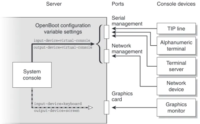
You must also ensure that the system console is directed to the appropriate port on the Sun Fire T2000 server’s back panel—generally, the one to which your hardware console device is attached (seeFIGURE 1-1). You do this by setting theinput-device
andoutput-deviceOpenBoot configuration variables.
FIGURE 1-1 Directing the System Console
Default System Console Connection Through the Serial
Management and Network Management Ports
On your server, the system console comes preconfigured to allow input and output only by means of the system controller. The system controller must be accessed either through the serial management port (SER MGT) or the network management port (NET MGT). By default, the network management port is configured to retrieve network configuration using DHCP and to allow connections using SSH. You can modify the network management port configuration after connecting to ALOM CMT through either the serial or network management ports.
System console TIP line Alphanumeric terminal Terminal server Network device Graphics monitor OpenBoot configuration variable settings input-device=virtual-console output-device=virtual-console input-device=keyboard output-device=screen
Server Ports Console devices Serial management Network management Graphics card
Typically, you connect one of the following hardware devices to the serial management port:
■ Terminal server
■ Alphanumeric terminal or similar device
■ Tip line connected to another Sun computer
These constraints provide for secure access at the installation site.
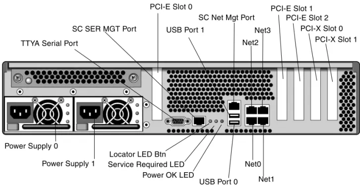
FIGURE 1-2 Rear I/O panel of the chassis—SC Serial Management Port Is The Default Console Connection
Note – USB ports 2 and 3 are located on the front panel
Using a Tip line enables you to use windowing and operating system features on the system making the connection to the Sun Fire T2000 server.
The serial management port is not a general-purpose serial port. If you want to use a general-purpose serial port with your server – to connect a serial printer, for instance – use the standard 9-pin serial port on the back panel of the Sun Fire T2000. The Solaris OS sees this port asttya.
SC SER MGT Port SC Net Mgt Port USB Port 1 Net2 Net3 PCI-E Slot 1 PCI-E Slot 2 PCI-X Slot 1 PCI-X Slot 0 TTYA Serial Port
Power Supply 0 Power Supply 1 PCI-E Slot 0 USB Port 0 Net0 Locator LED Btn
Service Required LED Power OK LED
For instructions on accessing the system console through a terminal server, see
“Accessing the System Console Through a Terminal Server” on page 10.
For instructions on accessing the system console through an alphanumeric terminal, see“Accessing the System Console Through an Alphanumeric Terminal” on page 15. For instructions on accessing the system console through a Tip line, see“Accessing the System Console Through a Tip Connection” on page 12.
On your server, the system console comes preconfigured to allow input and output only by means of the system controller. The system controller must be accessed either through the serial management port (SER MGT) or the network management port (NET MGT). By default, the network management port is configured to retrieve network configuration using DHCP and to allow connections using SSH. You can modify the network management port configuration after connecting to ALOM CMT through either the serial or network management ports. For more information, see
“Activating the Network Management Port” on page 8.
Alternative System Console Configuration
In the default configuration, system controller alerts and system console output appear interspersed in the same window.After initial system installation, you can redirect the system console to take its input from and send its output to a graphics card’s port.
For the following reasons, the best practice is to leave the console port in its default configuration:
■ In a default configuration, the serial management and network management ports enable you to open up to eight additional windows through which you can view, but not affect, system console activity. You cannot open these connections if the system console is redirected to a graphics card’s port.
■ In a default configuration, the serial management and network management ports enable you to switch between viewing system console and system controller output on the same device by typing a simple escape sequence or command. The escape sequence and command do not work if the system console is redirected to a graphics card’s port.
■ The system controller keeps a log of console messages, but some messages are not logged if the system console is redirected to a graphic card’s port. The omitted information could be important if you need to contact Sun customer service with a problem.
You change the system console configuration by setting OpenBoot configuration variables. See“System Console OpenBoot Configuration Variable Settings” on page 26.
Accessing the System Console Through a Graphics Monitor
The Sun Fire T2000 server is shipped without a mouse, keyboard, monitor, or frame buffer for the display of bitmapped graphics. To install a graphics monitor on the server, you must install a graphics accelerator card into a PCI slot, and attach a monitor, mouse, and keyboard to the appropriate front or rear USB ports.
After starting the system, you might need to install the correct software driver for the PCI card you have installed. For detailed hardware instructions, see“Accessing the System Console Through a Local Graphics Monitor” on page 15.
Note – POST diagnostics cannot display status and error messages to a local graphics monitor.
Accessing the System Controller
The following sections describe ways of accessing the system controller.
Using the Serial Management Port
This procedure assumes that the system console uses the serial management and network management ports (the default configuration).
When you are accessing the system console using a device connected to the serial management port, you first access the ALOM system controller and itssc>prompt. After connecting to the ALOM system controller, you can switch to the system console.
For more information about the ALOM system controller card, refer to the ALOM CMT guide for your server.
▼
To Use the Serial Management Port
1. Ensure that the serial port on your connecting device is set to the following parameters:
■ 9600 baud
■ 8 bits
■ 1 stop bit
■ No handshaking
2. Establish an ALOM system controller session.
See the ALOM CMT guide for your server for instructions.
3. To connect to the system console, at the ALOM system controller command prompt, type:
Theconsole command switches you to the system console.
4. To switch back to thesc>prompt, type the#.(Pound-Period) escape sequence.
Characters are not echoed to the screen.
For instructions on how to use the ALOM system controller, refer to the ALOM CMT guide for your server.
Activating the Network Management Port
The network management port is configured by default to retrieve network settings using DHCP and allow connections using SSH. You may need to modify these settings for your network. If you are unable to use DHCP and SSH on your network, you must connect to the system controller using the serial management port to reconfigure the network management port. See“Using the Serial Management Port” on page 7
Note – There is no default password when connecting to the system controller for the first time using the serial management port. When connecting to the system controller using the network management port for the first time, the default password is the last 8 digits of the Chassis Serial Number. The Chassis Serial Number can be found printed on the back of the server or in the printed system information sheet which shipped with your server. You must assign a password during initial system configuration. For more information, refer to your server installation guide and the ALOM CMT guide for your server.
sc> console
You can assign the network management port a static IP address or you can configure the port to obtain an IP address using the Dynamic Host Configuration Protocol (DHCP) from another server. The network management port can be configured to accept connections from Telnet clients or SSH clients, but not both. Data centers frequently devote a separate subnet to system management. If your data center has such a configuration, connect the network management port to this subnet.
Note – The network management port is a 10/100 BASE-T port. The IP address assigned to the network management port is a unique IP address, separate from the main Sun Fire T2000 server IP address, and is dedicated for use only with the ALOM system controller.
▼
To Activate the Network Management Port
1. Connect an Ethernet cable to the network management port.
2. Log in to the ALOM system controller through the serial management port. For more information about connecting to the serial management port, see
“Accessing the System Controller” on page 7. 3. Type one of the following commands:
■ If your network uses static IP addresses, type:
■ If your network uses Dynamic Host Configuration Protocol (DHCP), type:
4. Type one of the following commands:
■ If you intend to use Secure Shell (SSH) to connect to the system controller:
sc> setsc if_network true sc> setsc netsc_ipaddr ip-address sc> setsc netsc_ipnetmask ip-address sc> setsc netsc_ipgateway ip-address
sc> setsc netsc_dhcp true
■ - If you intend to use Telnet to connect to the system controller:
5. Reset the system controller so that the new settings take affect:
6. After the system controller resets, log in to the system controller and issue the
shownetworkcommand to verify network settings:
To connect through the network management port, use thetelnetorssh(based on the value you provided in Step 4) commands to the IP address you specified in
Step 3of the preceding procedure.
Accessing the System Console Through a
Terminal Server
The following procedure assumes that you are accessing the system console by connecting a terminal server to the serial management port (SER MGT) of the Sun Fire T2000 server.
▼
To Access The System Console Through a Terminal Server
1. Complete the physical connection from the serial management port to your terminal server.
The serial management port on the Sun Fire T2000 server is a data terminal
equipment (DTE) port. The pinouts for the serial management port correspond with the pinouts for the RJ-45 ports on the Serial Interface Breakout Cable supplied by Cisco for use with the Cisco AS2511-RJ terminal server. If you use a terminal server made by another manufacturer, check that the serial port pinouts of the Sun Fire T2000 server match those of the terminal server you plan to use.
If the pinouts for the server serial ports correspond with the pinouts for the RJ-45 ports on the terminal server, you have two connection options:
■ Connect a serial interface breakout cable directly to the Sun Fire T2000 server. See
“Accessing the System Controller” on page 7.
sc> setsc if_connection telnet
sc> resetsc
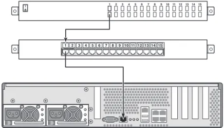
■ Connect a serial interface breakout cable to a patch panel and use the straight-through patch cable (supplied by Sun) to connect the patch panel to the server.
FIGURE 1-3 Patch Panel Connection Between a Terminal Server and a Sun Fire T2000
Server
If the pinouts for the serial management portdo notcorrespond with the pinouts for the RJ-45 ports on the terminal server, you need to make a crossover cable that takes each pin on the Sun Fire T2000 server serial management port to the corresponding pin in the terminal server’s serial port.
TABLE 1-2shows the crossovers that the cable must perform.
TABLE 1-2 Pin Crossovers for Connecting to a Typical Terminal Server
Sun Fire T2000 Serial Port (RJ-45 Connector)
Pin Terminal Server Serial Port Pin
Pin 1 (RTS) Pin 1 (CTS)
Pin 2 (DTR) Pin 2 (DSR)
Pin 3 (TXD) Pin 3 (RXD)
Pin 4 (Signal Ground) Pin 4 (Signal Ground) Pin 5 (Signal Ground) Pin 5 (Signal Ground)
Pin 6 (RXD) Pin 6 (TXD)
Pin 7 (DSR /DCD) Pin 7 (DTR)
2. Open a terminal session on the connecting device, and type:
For example, for a Sun Fire T2000 server connected to port 10000 on a terminal server whose IP address is 192.20.30.10, you would type:
Accessing the System Console Through a Tip
Connection
Use this procedure to access the Sun Fire T2000 server system console by connecting the serial management port (SER MGT) to the serial port of another Sun system (FIGURE 1-4).
FIGURE 1-4 Tip Connection Between a Sun Fire T2000 Server and Another Sun System
▼
To Access the System Console Through the Tip Connection
1. Connect the RJ-45 serial cable and, if required, the DB-9 or DB-25 adapter provided.
The cable and adapter connect between another Sun system’s serial port (typically TTYB) and the serial management port on the back panel of the Sun Fire T2000 server. Pinouts, part numbers, and other details about the serial cable and adapter are provided in the service manual for your server.
% telnet IP-address-of-terminal-server port-number
2. Ensure that the/etc/remotefile on the Sun system contains an entry for
hardwire.
Most releases of Solaris OS software shipped since 1992 contain an/etc/remote
file with the appropriatehardwireentry. However, if the Sun system is running an older version of Solaris OS software, or if the/etc/remotefile has been modified, you might need to edit it. See“Modifying the/etc/remoteFile” on page 13for details.
3. In a shell tool window on the Sun system, type:
The Sun system responds by displaying:
The shell tool is now a Tip window directed to the Sun Fire T2000 server through the Sun system’s serial port. This connection is established and maintained even when the Sun Fire T2000 server is completely powered off or just starting up.
Note – Use a shell tool or a CDE terminal (such asdtterm), not a command tool. Some Tip commands might not work properly in a command tool window.
Modifying the
/etc/remote
File
This procedure might be necessary if you are accessing the Sun Fire T2000 server using a Tip connection from a Sun system running an older version of the Solaris OS software. You might also need to perform this procedure if the/etc/remotefile on the Sun system has been altered and no longer contains an appropriatehardwire
entry.
Log in as superuser to the system console of a Sun system that you intend to use to establish a Tip connection to the Sun Fire T2000 server.
% tip hardwire
▼
To Modify the
/etc/remote
File
1. Determine the release level of Solaris OS software installed on the Sun system. Type:
The system responds with a release number.
2. Take one of the following actions, depending on the number displayed.
■ If the number displayed by theuname -rcommand is 5.0 or higher:
The Solaris OS software shipped with an appropriate entry forhardwirein the
/etc/remotefile. If you have reason to suspect that this file was altered and the
hardwireentry modified or deleted, check the entry against the following example, and edit it as needed.
Note – If you intend to use the Sun system’s serial port A rather than serial port B, edit this entry by replacing/dev/term/bwith/dev/term/a.
■ If the number displayed by theuname -rcommand is less than 5.0:
Check the/etc/remotefile and add the following entry, if it does not already exist.
Note – If you intend to use the Sun system’s serial port A rather than serial port B, edit this entry by replacing/dev/ttybwith/dev/ttya.
The/etc/remotefile is now properly configured. Continue establishing a Tip connection to the Sun Fire T2000 server system console. See“Accessing the System Console Through a Tip Connection” on page 12.
If you have redirected the system console to TTYB and want to change the system console settings back to use the serial management and network management ports, see“System Console OpenBoot Configuration Variable Settings” on page 26.
# uname -r
hardwire:\
:dv=/dev/term/b:br#9600:el=^C^S^Q^U^D:ie=%$:oe=^D:
hardwire:\
Accessing the System Console Through an
Alphanumeric Terminal
Use this procedure when you are accessing the Sun Fire T2000 server system console by connecting the serial port of an alphanumeric terminal to the serial management port (SER MGT) of the Sun Fire T2000 server.
▼
To Access the System Console Through an Alphanumeric
Terminal
1. Attach one end of the serial cable to the alphanumeric terminal’s serial port. Use a null modem serial cable or an RJ-45 serial cable and null modem adapter. Connect this cable to the terminal’s serial port connector.
2. Attach the opposite end of the serial cable to the serial management port on the Sun Fire T2000 server.
3. Connect the alphanumeric terminal’s power cord to an AC outlet. 4. Set the alphanumeric terminal to receive:
■ 9600 baud
■ 8 bits
■ No parity
■ 1 stop bit
■ No handshake protocol
Refer to the documentation accompanying your terminal for information about how to configure the terminal.
You can issue system commands and view system messages using the alphanumeric terminal. Continue with your installation or diagnostic procedure, as needed. When you are finished, type the alphanumeric terminal’s escape sequence.
For more information about connecting to and using the ALOM system controller, refer to the ALOM CMT guide for your server.
Accessing the System Console Through a Local
Graphics Monitor
After initial system installation, you can install a local graphics monitor and configure it to access the system console. Youcannotuse a local graphics monitor to perform initial system installation, nor can you use a local graphics monitor to view power-on self-test (POST) messages.
To install a local graphics monitor, you must have the following items:
■ Supported PCI-based graphics frame buffer card and software driver
■ Monitor with appropriate resolution to support the frame buffer
■ Supported USB keyboard
■ Supported USB mouse and mouse pad
▼
To Access the System Console Through a Local Graphics
Monitor
1. Install the graphics card into an appropriate PCI slot.
Installation must be performed by a qualified service provider. For further information, refer to the service manual for your server or contact your qualified service provider.
2. Attach the monitor’s video cable to the graphics card’s video port. Tighten the thumbscrews to secure the connection.
3. Connect the monitor’s power cord to an AC outlet.
4. Connect the USB keyboard cable to one USB port and the USB mouse cable to the other USB port on the Sun Fire T2000 server back panel (FIGURE 1-2).
5. Get to theokprompt.
For more information, see“Getting to theokPrompt” on page 24. 6. Set OpenBoot configuration variables appropriately.
From the existing system console, type:
Note – There are many other system configuration variables. Although these variables do not affect which hardware device is used to access the system console, some of them affect which diagnostic tests the system runs and which messages the system displays at its console. For details, refer to the service manual for your server. 7. To cause the changes to take effect, type:
The system stores the parameter changes, and boots automatically when the OpenBoot configuration variableauto-boot?is set totrue(the default value).
ok setenv input-device keyboard
ok setenv output-device screen
Note – To store parameter changes, you can also power cycle the system using the front panel Power button.
You can issue system commands and view system messages using your local graphics monitor. Continue with your installation or diagnostic procedure, as needed.
If you want to redirect the system console back to the serial management and network management ports, see“System Console OpenBoot Configuration Variable Settings” on page 26.
Switching Between the System
Controller and the System Console
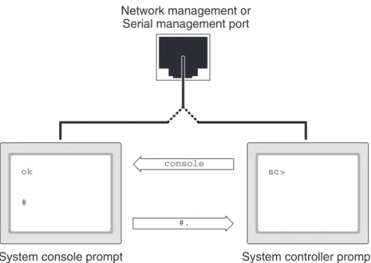
The system controller features two management ports, labeled SER MGT and NET MGT, located on the server’s back panel. If the system console is directed to use the serial management and network management ports (the default configuration), these ports provide access to both the system console and the ALOM CMT command-line interface (the ALOM system controller prompt), each on a separate channel (see
FIGURE 1-5).
FIGURE 1-5 Separate System Console and System Controller Channels
If the system console is configured to be accessible from the serial management and network management ports, when you connect through one of these ports you can access either the ALOM CMT command-line interface or the system console. You can switch between the ALOM system controller prompt and the system console at any time, but you cannot access both at the same time from a single terminal window or shell tool.
ok
#
Network management or Serial management port
System console prompt
sc>
System controller prompt
console
The prompt displayed on the terminal or shell tool tells you which channel you are accessing:
■ The#or%prompt indicates that you are at the system console and that the Solaris OS is running.
■ Theokprompt indicates that you are at the system console and that the server is running under OpenBoot firmware control.
■ Thesc>prompt indicates that you are at the system controller.
Note – If no text or prompt appears, it might be that no console messages were recently generated by the system. If this happens, pressing the terminal’s Enter or Return key should produce a prompt.
To reach the system console from the system controller,
■ Type theconsolecommand at thesc>prompt. To reach the system controller from the system console,
■ Type the system controller escape sequence,
By default, the escape sequence is#.(Pound-Period).
For more information about communicating with the system controller and system console, see:
■ “Communicating With the System” on page 1 ■ “ALOM CMTsc>Prompt” on page 19 ■ “OpenBootokPrompt” on page 21
■ “Accessing the System Controller” on page 7 ■ The ALOM CMT guide for your server
ALOM CMT
sc>
Prompt
The ALOM system controller runs independently of the server and regardless of system power state. When you connect your server to AC power, the ALOM system controller immediately starts up, and begins monitoring the system.
Note – To view ALOM system controller boot messages, you must connect an alphanumeric terminal to the serial management portbeforeconnecting the AC power cords to the Sun Fire T2000 server.
You can log in to the ALOM system controller at any time, regardless of system power state, as long as AC power is connected to the system and you have a way of interacting with the system. You can also access the ALOM system controller prompt (sc>) from the OpenBootokprompt or from the Solaris#or%prompt, provided the system console is configured to be accessible through the serial management and network management ports.
Thesc>prompt indicates that you are interacting with the ALOM system controller directly. It is the first prompt you see when you log in to the system through the serial management port or network management port, regardless of system power state.
Note – When you access the ALOM system controller for the first time and you issue an administrative command, the controller forces you to create a password (for the default username:admin) for subsequent access. After this initial configuration, you will be prompted to enter a user name and password every time you access the ALOM system controller.
For more information, see the following:
“Getting to theokPrompt” on page 24
“Switching Between the System Controller and the System Console” on page 18
Access Through Multiple Controller Sessions
Up to nine ALOM CMT sessions can be active concurrently, one session through the serial management port and up to eight sessions through the network management port. Users of each of these sessions can issue commands at thesc>prompt. However, only one user at a time can access the system console, and then only if the system console is configured to be accessible through the serial and network management ports. For more information, see:
“Accessing the System Controller” on page 7
“Activating the Network Management Port” on page 8
Any additional ALOM CMT sessions afford passive views of system console activity, until the active user of the system console logs out. However, theconsole -f
command, if you enable it, allows users to seize access to the system console from one another. For more information, see the ALOM CMT guide for your server.
Reaching the
sc>
Prompt
There are several ways to get to thesc>prompt:
■ If the system console is directed to the serial management and network management ports, you can type the ALOM CMT escape sequence (#.).
■ You can log in directly to the system controller from a device connected to the serial management port. See“Accessing the System Controller” on page 7.
■ You can log in directly to the system controller using a connection through the network management port. See“Activating the Network Management Port” on page 8.
OpenBoot
ok
Prompt
A Sun Fire T2000 server with the Solaris OS installed operates at differentrun levels. For a full description of run levels, refer to the Solaris system administration documentation.
Most of the time, you operate a Sun Fire T2000 server at run level 2 or run level 3, which are multiuser states with access to full system and network resources. Occasionally, you might operate the system at run level 1, which is a single-user administrative state. However, the lowest operational state is run level 0. At this state, it is safe to turn off power to the system.
When a Sun Fire T2000 server is at run level 0, theokprompt appears. This prompt indicates that the OpenBoot firmware is in control of the system.
There are a number of scenarios under which OpenBoot firmware control can occur.
■ By default, before the operating system is installed the system comes up under OpenBoot firmware control.
■ When theauto-boot?OpenBoot configuration variable is set tofalse, the system boots to theokprompt.
■ When the operating system is halted, the system transitions to run level 0 in an orderly way.
■ When the operating system crashes, the system reverts to OpenBoot firmware control.
■ During the boot process, when there is a serious hardware problem that prevents the operating system from running, the system reverts to OpenBoot firmware control.
■ When a serious hardware problem develops while the system is running, the operating system transitions smoothly to run level 0.
■ When you deliberately place the system under firmware control in order to execute firmware-based commands.
It is the last of these scenarios which most often concerns you as an administrator, since there will be times when you need to reach theokprompt. Several ways to do this are outlined in“Reaching theokPrompt” on page 22. For detailed instructions, see“Getting to theokPrompt” on page 24.
Reaching the
ok
Prompt
There are several ways to reach theokprompt, depending on the state of the system and the means by which you are accessing the system console. In order of
desirability, these are:
■ Graceful shutdown
■ ALOM system controllerbreakandconsolecommand pair
■ L1-A (Stop-A) keys or Break key
■ Manual system reset
A discussion of each method follows. For step-by-step instructions, see“Getting to theokPrompt” on page 24.
Note –As a rule, before suspending the operating system, you should back up files, warn users of the impending shutdown, and halt the system in an orderly manner. However, it is not always possible to take such precautions, especially if the system is malfunctioning.
Graceful Shutdown
The preferred method of reaching theokprompt is to shut down the operating system by issuing an appropriate command (for example, theshutdown,init, or
uadmincommand) as described in Solaris system administration documentation. You can also use the system Power button to initiate a graceful system shutdown. Gracefully shutting down the system prevents data loss, enables you to warn users beforehand, and causes minimal disruption. You can usually perform a graceful shutdown, provided the Solaris OS is running and the hardware has not experienced serious failure.
You can also perform a graceful system shutdown from the ALOM system controller command prompt.
ALOM CMT
break
or
console
Command
Typingbreakfrom thesc>prompt forces a running Sun Fire T2000 server to drop into OpenBoot firmware control. If the operating system is already halted, you can use theconsolecommand instead ofbreakto reach theokprompt.
Note – After forcing the system into OpenBoot firmware control, be aware that issuing certain OpenBoot commands (likeprobe-scsi,probe-scsi-all, or
probe-ide) might hang the system.
L1-A (Stop-A) Keys or Break Key
When it is impossible or impractical to shut down the system gracefully, you can get to theokprompt by typing the L1-A (Stop-A) key sequence from a Sun keyboard. If you have an alphanumeric terminal attached to the Sun Fire T2000 server, press the Break key.
Note – After forcing the system into OpenBoot firmware control, be aware that issuing certain OpenBoot commands (likeprobe-scsi,probe-scsi-all, or
probe-ide) might hang the system.
Note – These methods of reaching theokprompt will only work if the system console has been redirected to the appropriate port. For details, see“System Console OpenBoot Configuration Variable Settings” on page 26.
Manual System Reset
Caution – Forcing a manual system reset results in loss of system state data, and should be attempted only as a last resort. After a manual system reset, all state information is lost, which inhibits troubleshooting the cause of the problem until the problem reoccurs.
Use the ALOM system controllerresetcommand, orpoweronandpoweroff
commands, to reset the server. Reaching theokprompt by performing a manual system reset or by power-cycling the system should be the method of last resort. Using these commands result in the loss of all system coherence and state
information. A manual system reset could corrupt the server’s file systems, although thefsckcommand usually restores them. Use this method only when nothing else works.
Caution – Accessing theokprompt suspends the Solaris OS.
When you access theokprompt from a functioning Sun Fire T2000 server, you are suspending the Solaris OS and placing the system under firmware control. Any processes that were running under the operating system are also suspended, andthe state of such processes might not be recoverable.
The commands you run from theokprompt have the potential to affect the state of the system. This means that it is not always possible to resume execution of the operating system from the point at which it was suspended. Although thego
command will resume execution in most circumstances, in general, each time you drop the system down to theokprompt, you should expect to have to reboot the system to get back to the operating system.
For More Information
For more information about the OpenBoot firmware, refer to theOpenBoot 4.x Command Reference Manual.An online version of the manual is included with the OpenBoot Collection AnswerBook that ships with Solaris software.
Getting to the
ok
Prompt
This procedure provides several ways of reaching theokprompt. The methods are not equally desirable. For details about when to use each method, see“OpenBootok
Prompt” on page 21.
Caution –Obtaining theokprompt suspends all application and operating system software. After you issue firmware commands and run firmware-based tests from theokprompt, the system might not be able to resume where it left off.
If possible, back up system data before starting this procedure. Also exit or stop all applications, and warn users of the impending loss of service. For information about the appropriate backup and shutdown procedures, see Solaris system administration documentation.
▼
To Obtain the
ok
Prompt
1. Decide which method you need to use to reach theokprompt. See“OpenBootokPrompt” on page 21for details.
2. Follow the appropriate instructions inTABLE 1-3.
TABLE 1-3 Ways of Accessing theokPrompt
Access Method What to Do
Graceful shutdown of the Solaris OS
From a shell or command tool window, issue an appropriate command (for example, theshutdownorinitcommand) as described in Solaris system administration documentation. L1-A (Stop-A) keys or
Break key
• From a Sun keyboard connected directly to the Sun Fire T2000 server, press the Stop and A keys simultaneously.*
–or–
• From an alphanumeric terminal configured to access the system console, press the Break key.
* Requires the OpenBoot configuration variableinput-device=keyboard. For more information, see “Ac-cessing the System Console Through a Local Graphics Monitor” on page 15and“System Console OpenBoot Configuration Variable Settings” on page 26.
ALOM system controllerbreakand
consolecommands
From thesc>prompt, type thebreakcommand. Then issue the
consolecommand, provided the operating system software is not running and the server is already under OpenBoot firmware control.
Manual system reset From thesc>prompt, type:
sc>bootmode bootscript=”setenv auto-boot? false” Press Enter.
then type:
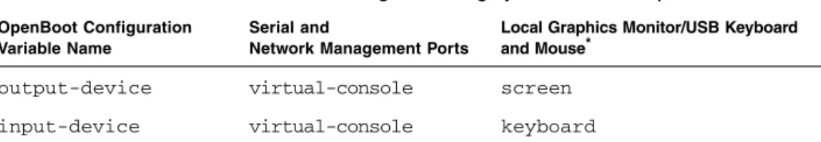
System Console OpenBoot
Configuration Variable Settings
The Sun Fire T2000 system console is directed to the serial management and network management ports (SER MGT and NET MGT) by default. However, you can redirect the system console to a local graphics monitor, keyboard, and mouse. You can also redirect the system console back to the serial management and network management ports.
Certain OpenBoot configuration variables control from where system console input is taken and to where its output is directed. The table below shows how to set these variables in order to use the serial management and network management ports, or a local graphics monitor as the system console connection.
* POST output will still be directed to the serial management port, as POST has no mechanism to direct its output to a graphics monitor.
The serial management port does not function as a standard serial connection. (If you want to connect a conventional serial device (such as a printer) to the system, you must connect it to ttya not the serial management port.)
It is important to note that thesc>prompt and POST messages are only available through the serial management port and network management port. Note that the ALOM system controllerconsolecommand is ineffective when the system console is redirected to a local graphics monitor.
In addition to the OpenBoot configuration variables described inTABLE 1-4, there are other variables that affect and determine system behavior. These variables are discussed in more detail inAppendix A.
TABLE 1-4 OpenBoot Configuration Variables That Affect the System Console
OpenBoot Configuration Variable Name
Setting for Sending System Console Output to:
Serial and
Network Management Ports
Local Graphics Monitor/USB Keyboard and Mouse*
output-device virtual-console screen
C H A P T E R
2
Managing RAS Features and System
Firmware
This chapter describes how to manage reliability, availability, and serviceability (RAS) features and system firmware, including ALOM CMT on the system
controller, and automatic system recovery (ASR). In addition, this chapter describes how to unconfigure and reconfigure a device manually, and introduces multipathing software.
This chapter contains the following sections:
■ “ALOM CMT and The System Controller” on page 27 ■ “OpenBoot Emergency Procedures” on page 33 ■ “Automatic System Recovery” on page 35
■ “Unconfiguring and Reconfiguring Devices” on page 40 ■ “Displaying System Fault Information” on page 41 ■ “Multipathing Software” on page 42
■ “Storing FRU Information” on page 43
Note – This chapter does not cover detailed troubleshooting and diagnostic procedures. For information about fault isolation and diagnostic procedures, refer to the service manual for your server.
ALOM CMT and The System Controller
The ALOM system controller supports a total of nine concurrent sessions per server, eight connections available through the network management port and one
After you log in to your ALOM CMT account, the ALOM system controller command prompt (sc>) appears, and you can enter ALOM system controller commands. If the command you want to use has multiple options, you can either enter the options individually or grouped together, as shown in the following example. The commands are identical.
Logging In To ALOM CMT
All environmental monitoring and control is handled by ALOM CMT on the ALOM system controller. The ALOM system controller command prompt (sc>) provides you with a way of interacting with ALOM CMT. For more information about the
sc>prompt, see“ALOM CMTsc>Prompt” on page 19.
For instructions on connecting to the ALOM system controller, see:
■ “Accessing the System Controller” on page 7
■ “Activating the Network Management Port” on page 8
Note – This procedure assumes that the system console is directed to use the serial management and network management ports (the default configuration).
sc> poweroff -f -y sc> poweroff -fy
▼
To Log In To ALOM CMT
1. If you are logged in to the system console, type#.(Pound-Period) to get to the
sc>prompt.
Press the Pound key, followed by the Period key. Then press the Return key. 2. At the ALOM CMT login prompt, enter the login name and press Return.
The default login name isadmin.
3. At the password prompt, enter the password and press Return twice to get to the
sc>prompt.
Note – There is no default password. You must assign a password during initial system configuration. For more information, refer to the installation guide and ALOM CMT guide for your server.
Caution – In order to provide optimum system security, best practice is to change the default system login name and password during initial setup.
Using the ALOM system controller, you can monitor the system, turn the Locator LED on and off, or perform maintenance tasks on the ALOM system controller card itself. For more information, refer to the ALOM CMT guide for your server.
▼
To View Environmental Information
1. Log in to the ALOM system controller.
2. Use theshowenvironmentcommand to display a snapshot of the server’s environmental status.
The information this command can display includes temperature, power supply status, front panel LED status, and so on.
Sun(tm) Advanced Lights Out Manager 1.0.12 Please login: admin
Please Enter password:
Note – Some environmental information might not be available when the server is in standby mode.
Note – You do not need ALOM system controller user permissions to use this command.
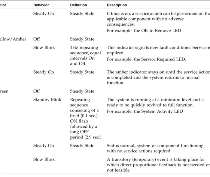
Interpreting System LEDs
The behavior of LEDs on the Sun Fire T2000 Server conform to the American National Standards Institute (ANSI) Status Indicator Standard (SIS). These standard LED behaviors are described inTABLE 2-1.
The LEDs have assigned meanings, described inTABLE 2-2.
TABLE 2-1 LED Behavior and Meaning
LED Behavior Meaning
Off The condition represented by the color is not true. Steady on The condition represented by the color is true.
Standby blink The system is functioning at a minimal level and ready to resume full function.
Slow blink Transitory activity or new activity represented by the color is taking place.
Fast blink Attention is required.
Feedback flash Activity is taking place commensurate with the flash rate (such as disk drive activity).
TABLE 2-2 LED Behaviors with Assigned Meanings Color Behavior Definition Description
White Off Steady state
Fast blink 4Hz repeating sequence, equal intervals On and Off.
This indicator helps you to locate a particular enclosure, board, or subsystem.
For example, the Locator LED.
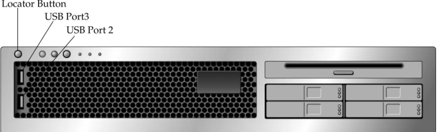
Controlling the Locator LED
You control the Locator LED from thesc>prompt or by the locator button on the front of the chassis.
Steady On Steady State If blue is on, a service action can be performed on the applicable component with no adverse
consequences.
For example: the OK-to-Remove LED Yellow/Amber Off Steady State
Slow Blink 1Hz repeating sequence, equal intervals On and Off.
This indicator signals new fault conditions. Service is required.
For example: the Service Required LED.
Steady On Steady State The amber indicator stays on until the service action is completed and the system returns to normal function.
Green Off Steady State
Standby Blink Repeating sequence consisting of a brief (0.1 sec.) ON flash followed by a long OFF period (2.9 sec.)
The system is running at a minimum level and is ready to be quickly revived to full function. For example: the System Activity LED
Steady On Steady State Status normal; system or component functioning with no service actions required
Slow Blink A transitory (temporary) event is taking place for which direct proportional feedback is not needed or not feasible.
TABLE 2-2 LED Behaviors with Assigned Meanings(Continued)
FIGURE 2-1 LocatorButton on Sun Fire T2000 Chassis
● To turn on the Locator LED, from the ALOM system controller command prompt, type:
● To turn off the Locator LED, from the ALOM system controller command prompt, type:
● To display the state of the Locator LED, from the ALOM system controller command prompt, type:
Note – You do not need user permissions to use thesetlocatorand
showlocatorcommands
sc> setlocator on Locator LED is on.
sc> setlocator off Locator LED is off.
sc> showlocator Locator LED is on.
Locator Button USB Port3
OpenBoot Emergency Procedures
The introduction of Universal Serial Bus (USB) keyboards with the newest Sun systems has made it necessary to change some of the OpenBoot emergency procedures. Specifically, theStop-N,Stop-D, andStop-Fcommands that were available on systems with non-USB keyboards are not supported on systems that use USB keyboards, such as the Sun Fire T2000 Server. If you are familiar with the earlier (non-USB) keyboard functionality, this section describes the analogous OpenBoot emergency procedures available in newer systems that use USB keyboards.
OpenBoot Emergency Procedures for Sun Fire
T2000 Systems
The following sections describe how to perform the functions of the Stop commands on systems that use USB keyboards, such as the Sun Fire T2000 Server server. These same functions are available through Sun Advanced Lights Out Manager (ALOM) system controller software.
Stop-A Functionality
Stop-A (Abort) key sequence works the same as it does on systems with standard keyboards, except that it does not work during the first few seconds after the server is reset. In addition, you can issue the ALOM system controllerbreakcommand. For more information, see“Reaching theokPrompt” on page 22.
Stop-N Functionality
Stop-N functionality is not available. However, the Stop-N functionality can be closely emulated by completing the following steps, provided the system console is configured to be accessible using either the serial management port or the network management port.
▼
To Restore OpenBoot Configuration Defaults
2. Type the following command:
Note – If you do not issue thepoweroffandpoweroncommands or thereset
command within 10 minutes, the host server ignores thebootmodecommand. You can issue thebootmodecommand without arguments to display the current setting
3. To reset the system, type the following commands:
4. To view console output as the system boots with default OpenBoot configuration variables, switch toconsolemode.
5. Typeset-defaultsto discard any customized IDPROM values and to restore the default settings for all OpenBoot configuration variables.
Stop-F Functionality
The Stop-F functionality is not available on systems with USB keyboards.
sc> bootmode reset_nvram
sc> bootmode bootscript="setenv auto-boot? false" sc>
sc> bootmode
Bootmode: reset_nvram
Expires WED SEP 09 09:52:01 UTC 2005 bootscript="setenv auto-boot? false"
sc> reset
Are you sure you want to reset the system [y/n]? y sc>
sc> console
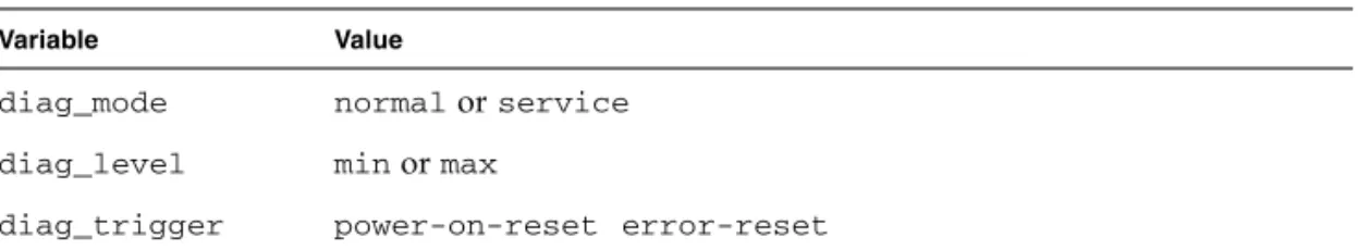
Stop-D Functionality
The Stop-D (Diags) key sequence is not supported on systems with USB keyboards. However, the Stop-D functionality can be closely emulated by setting the virtual keyswitch todiag, using the ALOM CMTsetkeyswitchcommand. For more information, refer to the ALOM CMT guide for your server.
Automatic System Recovery
The system provides for automatic system recovery (ASR) from failures in memory modules or PCI cards.
Automatic system recovery functionality enables the system to resume operation after experiencing certain nonfatal hardware faults or failures. When ASR is enabled, the system’s firmware diagnostics automatically detect failed hardware components. An auto-configuring capability designed into the system firmware enables the system to unconfigure failed components and to restore system operation. As long as the system is capable of operating without the failed component, the ASR features enable the system to reboot automatically, without operator intervention.
Note – ASR is not activated until you enable it. See“Enabling and Disabling Automatic System Recovery” on page 38.
For more information about ASR, refer to the service manual for your server.
Auto-Boot Options
The system firmware stores a configuration variable calledauto-boot?, which controls whether the firmware will automatically boot the operating system after each reset. The default setting for Sun platforms istrue.
Normally, if a system fails power-on diagnostics,auto-boot?is ignored and the system does not boot unless an operator boots the system manually. An automatic boot is generally not acceptable for booting a system in a degraded state. Therefore, the Sun Fire T2000 Server OpenBoot firmware provides a second setting,
degraded boot when a subsystem failure is detected. Both theauto-boot?and
auto-boot-on-error?switches must be set totrueto enable an automatic degraded boot. To set the switches, type:
Note – The default setting forauto-boot-on-error?isfalse. The system will not attempt a degraded boot unless you change this setting totrue. In addition, the system will not attempt a degraded boot in response to any fatal nonrecoverable error, even if degraded booting is enabled. For examples of fatal nonrecoverable errors, see“Error Handling Summary” on page 36.
Error Handling Summary
Error handling during the power-on sequence falls into one of the following three cases:
■ If no errors are detected by POST or OpenBoot firmware, the system attempts to boot ifauto-boot?istrue.
■ If only nonfatal errors are detected by POST or OpenBoot firmware, the system attempts to boot ifauto-boot?istrueandauto-boot-on-error?istrue. Nonfatal errors include the following:
■ SAS subsystem failure. In this case, a working alternate path to the boot disk is
required. For more information, see“Multipathing Software” on page 42.
■ Ethernet interface failure. ■ USB interface failure. ■ Serial interface failure. ■ PCI card failure.
■ Memory failure. Given a failed DIMM, the firmware will unconfigure the entire
logical bank associated with the failed module. Another nonfailing logical bank must be present in the system for the system to attempt a degraded boot.
Note – If POST or OpenBoot firmware detects a nonfatal error associated with the normal boot device, the OpenBoot firmware automatically unconfigures the failed device and tries the next-in-line boot device, as specified by theboot-device
configuration variable.
ok setenv auto-boot? true