ITERATIVE FUNCTION SYSTEM ALGORITHM BASED
A CONFORMAL FRACTAL TRANSFORMATION
FOR BATIK MOTIVE DESIGN
1,2RUSMONO YULIANTO, 2MOCHAMAD HARIADI, 3MAURIDHI HERY PURNOMO, 4KUNIO
KONDO
1Computer Science Department, Center for Development and Empowerment for Arts and Culture Teachers
and Educational Personnel, Indonesia
2,3Electrical Engineering Department, Sepuluh Nopember Institute of Technology, Indonesia 4
School of Media Science, Tokyo University of Technology. E-mail: [email protected]
ABSTRACT
Recently, Indonesia has a traditional painting motive which is widely known as Batik. Usually, Batik is implemented as a motive for wall, car, clothes and even airplane. Batik is also as a formal dress code in international meeting. The Batik motive creation recently produced using traditional tools. Therefore, the motive rules are creatively design in a traditional fashioned. This research proposes a new method for creating motive rules to enhance traditional fashioned Batik motive design. This will lead to more inspirational innovation for batik motive designer. This research describes a method for creating Batik motive rules based on fractal (IFS). First, a morphological erosion process is generated to create template, while repetition and pattern placement are conducted under Conformal Fractal Transformation based on Iterated Function System. Iterated Function System also conducts extensive restriction to object formed. The experimental results have shown that Batik motive produced Conformal Fractal dimension is 1.83644, whereas the average of error value is 0.0808%. It shows that our proposed method is closed to excellent, because the value of error is less than 1%. The experimental results have been also verified by qualified Batik teachers as respondents coming from different parts of Indonesia. The verification results show that more than 82% stated that, the experimental results have been stated as Batik pattern.
Keywords: Batik, Iterated Function System, Conformal Transformation, Affine Transformation
1.
INTRODUCTIONBatik motive can be divided into two models, which are fractal Batik and ISEN motive. Fractal Batik is Batik that has fractal motive, is a motive that based on rule that rised with transformation and the result is Batik motive. Isen batik is used as the contain of batik motive. According to Falconer, Fractal has five characteristics, which are soft structures, irregular shape, fractal dimensional has greater than its topology, and recursive. Generally, fractal has integer dimension, such as line has 1 dimension, area has 2 dimensions, and cubic has 3 dimensions, but fractal has fractional dimensions.
Fractal method has been utilized by researcher to generate graphics [1-9], such as batik generator [1], fractal image de-noising [3], and texture analysis [7]. One of the most interesting on fractal implementation is used to generate Batik motive.
Batik is well known as one of heritage of Javanese culture, but it has been widely studied by scientist overseas. Therefore, it is necessary to develop batik motive that can be developed rapidly based on Iterated Function System and Conformal Fractal Transformation. We proposed to design Batik by using Iterated Function System and followed by using Conformal Fractal Transformation.
This paper is written as follows. Proposed method is presented on section 2 followed by experimental analysis on section 3. The results of analysis have been concluded on section 4.
2.
MATHEMATICAL FUNDAMENTAL ∆ ∆ + − = y x y S x S y x y x ) cos( ) sin( ) sin( ) cos( ' '
α
α
α
α
(1)In this case α represents angle, S is scaling, whereas translation is represented by using ∆. The results of affine transformation are represented by using x’ and y’. Equation (1) can be used as conformal transformation for special condition.
Conformal transformation can be conducted by using special condition of Equation (1). Conformal transformation also uses other equation to generate pattern such as graphics, batik or other image. Equation of tan (z), the first and the second derivatives are commonly used as conformal equation as seen on the following
)
cos(
)
sin(
)
tan(
)
(
z
z
z
z
f
=
=
(2)) ( sec ) ( cos 1 ) ( cos ) ( sin ) ( cos ) ( cos ) sin( ). sin( ) cos( ). cos( ' ' 2 2 2 2 2 2 2 z z z z z z z z z z V U V V U dz df = = + = + = − =
(3)
(
)
(
)
)
tan(
)
(
sec
2
)
tan(
)
sec(
)
sec(
2
)
(
sec
2 2 2 2z
z
z
z
z
z
dz
d
dz
df
dz
d
dz
f
d
=
=
=
=
(4)
f(z) is utilized as Conformal Transformation on
the 1st model,
dz
df
is used as Conformal
Transformation on the 2nd model, whereas on the 3rd
model of Conformal Transformation used 2
2
dz
f
d
.
3.
BATIK MOTIVE STRUCTURINGOne of the base methods that is used to make motif batik fractal design is using iterated function
system. This is a method for making fractal, which consists of a group of some rule self similarity, and then the transformation is done by using a group of rotation function, scale, and translation, with modification of morphology and Conformal Transformation process. For comparison the size of fractal needed by fractal dimension, that have function to measure density fractal that placing metric room.
3.1. Iterated Function System
Iterated Function System is well-known as IFS. It is an object formation process by placing objects on a regular basis. The formation object is conducted repeatedly. IFS is also used to develop regular pattern, such as Batik. However IFS cannot be able optimally work, without being combined to other method. In this research we combined IFS and Conformal Transformation to develop Batik pattern.
3.2. Conformal Fractal Trasformation
[image:2.612.93.293.273.693.2]In this research, we propose new approach to design Batik by using 2 main stages, which are modification of morphological process and Conformal Transformation process based on Iterated Function System as seen in Figure 1. We use tan (z) function and its derivation on the Conformal Transformation process to obtain batik pattern.
Figure 1. Frame Work System of Proposed Method
Figure 2. Modification of Morphological Process
The first stage, image input is converted
gray scale image, using the following
equation
B G
R y
x
f( , )=0.2989* +0.587* +0.114*
(5)
The second stage, the result of Equation (1) is used to determine the best threshold. It is needed to achieve binary image. It can be obtained by using Otsu’s method. The optimal threshold can be determined
( )
T(
B( )
k)
N k opt B
2
1 2
max
maxσ σ
≤ ≤
= (6)
Variance value on the equation (6) can be obtained by determining the mean value of intensity probability distribution p(l).
( ) ( )
(
)
( )
k
(
( )
k
)
k
k
T
and
l
p
l
T
B N
l
ω
ω
ω
µ
µ
σ
µ
−
−
=
=
∑
=
1
.
)
(
.
2 1 max
In this case, p(l) can be defined by using
2
)
(
)
(
N
l
N
l
p
=
(9)The result of equation (8) was utilized to determine the zero and the first order cumulative moment as seen on the following function
∑
∑
= =
=
=
k
l k
l
l
p
l
k
and
l
p
k
1 1
)
(
.
)
(
)
(
)
(
µ
ω
The third stage, binary image is obtained by using the best threshold of Equation (6). Modeling of binary image can be determined by using
<
≥
=
opt opt biner
T
y
x
f
if
T
y
x
f
if
y
x
f
)
,
(
0
)
,
(
255
)
,
(
(12)The result of equation (10) consists of some noise. On the fourth stage, the results of Equation (10) are removed noises, it is necessary to build the removing noise model. Noise can be defined as region less than Rnoise. In this research,
we defined Rnoise=20 pixels. For each Object(i),
where i∈1..number of objects, it has been replaced with background image when Object(i) less than
Rnoise
.
The last stage, morphology process is started with structuring element building. We use structuring element with r=1 as seen on the following matrix equation
=
0
1
0
1
1
1
0
1
0
Se
(13)Matrix equation (11) is used to erode object results of Equation (10). Erosion can be done by operating the Se matrix to the image. Part of the image will be removed if there are parts of Se are beyond of the image. In this research, we repeated twice to erode image. The result of image erosion was resized into 1024x1024 pixels.
Conformal Transformation process based on Iterated Function System stage is started with blocks partition without overlapping. It is well-known as range block. The next process is conducting conformal transformation to achieve local similarity on the bigger block. It is named as domain block. In this research, the block size chosen has 50% size of range block, the results of (7)
(8)
(10)
process is well-known as Iterated Function System. In this research, we use 3 conformal transformation equations, which are tan (z), the first derivative of tan (z) and the second derivative of tan (z) as seen IN Equation (2), (3) and (4)
Conformal transformation mapped variable by applying linear combination of translation, scaling, rotation, and shearing. In this research we utilize six parameters, which are mx, my, αx,
αy, ∆x’ dan ∆y’. They used on the equations
∆ ∆ +
− =
' ' )
cos( ) sin(
) sin( ) cos( '
'
y x y m
x m y
x
y x
x x
x x
α α
α
α (14)
Equation (12) can be solved as seen on the following equation
' *
) sin( *
) cos(
' m x m y x
x=
α
x x +α
x y +∆ (15)and
' *
) cos( *
) sin(
' m x m y y
y=−
α
x x +α
x y +∆ (16)Conformal transformation is special affine transformation, where the value of mxx=myy=m and
αx = αy = α, so the equation (13) and (14) can be
changed
'
)
sin(
*
)
cos(
*
'
m
m
x
x
=
α
+
α
+
∆
(17)and
'
)
cos(
*
)
sin(
*
'
m
m
y
y
=
−
α
+
α
+
∆
(18)3.3.Fractal Dimension
Fractal have fractional dimension. The method used to count the fractal object dimension is Box Counting method. It can be expressed by using
( )
(
( )
( )
)
s
s
N
D
slog
log
=
(19)N(s) represents regular box, whereas s consists of pixel information and D(s) represents fractal object with size s. We propose Box counting algorithm as follows
1. Image is divided into grid with size s. Number of boxes N(s) depend on s value, in this research the value of s ranging between 1 until 2k, and k∈1..w (w represents image width)
2. Compute D(s) using equation (17)
3. Create line based on the value of log(s) and log(N(s) as the x-axis and y-ordinate
4. EXPERIMENTAL RESULT AND
ANALYSIS
[image:4.612.316.509.243.279.2]We have conducted three experimental scenarios, which are Conformal Fractal Transformation using tan (z), the first and the second derivatives. For each scenario, we have set the seven parameters, which are number of rows, number of columns, number of iterations, the real value of u, the imaginer of u, the real of v and the imaginer of v. in this experiments, 5 figures have been used as basic image to generate Batik pattern as seen in Figure 3
Figure 3. Basic Image to Generate Batik Pattern
[image:4.612.348.485.374.505.2]We have conducted experimental using IFS as seen in Figure 4. IFS cannot be able create optimally Batik. therefore, it is necessary to combine into conformal transformation.
Figure 4. Experimental Result Using Iterated Function System
The following is an example of the processing results by using proposed method. In this case, we use the third image in Figure 3 as ornament basic. Ornaments yielded have unique pattern as Batik as seen shown on Figure 5
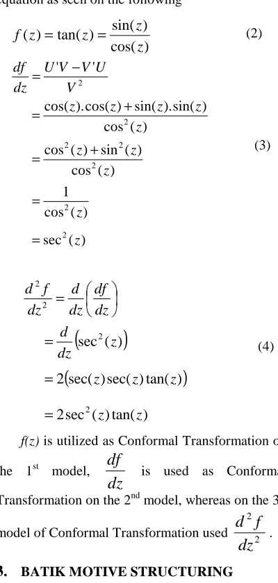
[image:4.612.322.514.616.710.2]The processing results by using Equation (2). We also utilized the third as ornament basic in Figure 3. The experimental results have dark color on the edge image as seen in Figure 5. It is caused by the characteristic of Equation (2), it can only work optimally on the centre of image.
Figure 5. Proposed Method Results Of Equation (2)
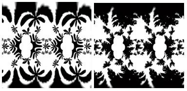
[image:5.612.313.518.213.397.2]The best results can be given by using Equation (3). Almost all of respondents said that Batik pattern yielded in Figure 6 is more real than Figure 3, 4 and 5.
Figure 6. Proposed Method Results Of Equation (3)
Table 1. Experimental Results Using Ifs Th
Imag e
IFS Fractal Dimensio
n
Regressi on
Error
Numbe r of Rows
Numbe r of Colum
ns
1 7 4 1.9037 0.99933 0.99000 67% 2 8 8 1.9422 0.9997 0.99000
3% 3 10 5 1.9739 0.99994 0.99000
06% 4 5 5 1.9089 0.99942 0.99000
58% 5 5 10 1.9675 0.99991 0.99000
09%
The IFS experimental results have obtained the fractal dimension values, are closed to 2, however the regression value yielded cannot be perfect, ie 1. We can also see error occurred. In this case, errors produced are very large. This proves that the IFS was not able to work optimally to generate a pattern of Batik.
We have also conducted verification toward Batik teachers as respondents coming from the different areas of Indonesia. They have given assessment to our experimental results. 82% respondents have stated that the experiment results in which we produce are batik pattern. The following is experimental results of our proposed method as seen on Table 2
Table 2 Experimental Results Of Our Proposes Method The
Ima ge
Conformal Model
Fractal Dimensio
n
Regression Error
1 1 1.6259 0.99158 0.8420% 2 1.6956 0.99996 0.0040% 3 1.6987 0.99825 0.1750% 2 1 1.8768 0,99991 0.0090% 2 1.7698 0.99923 0.0770% 3 1.7258 0.99985 0.0150% 3 1 1.9556 0.99995 0.0050% 2 1.7736 0.9999 0.0100% 3 1.8084 0.99991 0.0090% 4 1 1.9328 0.99982 0.0180% 2 1.9328 0.99982 0.0180% 3 1.9152 0.9998 0.0200% 5 1 1.9688 0.99999 0.0010% 2 1.9472 0.99991 0.0090% 3 1.9196 1 0.0000%
Fractal dimension resulted is close to 2, it shows that batik pattern of our proposed method is 2 dimension. As we know on Table 2, the smallest fractal dimension is 1. 6259 and the greatest dimension is 1.9688 (1.9688≈2). Based on Table 2
can be concluded that, the greatest error is smaller
than 1%, whereas the smallest error is 0%. It shows that conformal transformation yielded is closed to perfect.
5. CONCLUSION
[image:5.612.75.299.429.612.2]results have been also evaluated by Batik teachers from the different area. The verification results show that 82% of batik teachers said our experimental results have good ornament.
REFRENCES:
[1] Y. Hariadi, Fractal Geometry on Batik.Journal of Social Complexity. Bandung Fe Institute, 2008.
[2] W.Constantine and D. Percival, “Insightful Fractal Time Series Modelling And Analysis”, 19 April 2010.
[3] M. Ghazel, G. H. Freeman, and E. R. Vrscay,”Fractal Image Denoising”, IEEE Transactions On Image Processing, Vol. 12, No. 12, Desember 2003.
[4] Daniel Ashlock, Joseph Alexander Brown, Fitness Functions for Searching the Mandelbrot Set, 978-1-4244-7833-0/11/$26.00 Journal IEEE, 2011
[5] Mihai Ivanovici, Member, IEEE, and Noël Richard, Member, IEEE, Fractal Dimension of Color Fractal Images, IEEE Transactions on Image Processing, VOL. 20, NO. 1, JANUARY 2011
[6] Aouidi, J., and Slimane, M.B. Multi-Fractal Formalism for Quasi-Self-Similar Functions. Journal of Statistical Physics, Vol. 108, Nos. 3/4, August 2002 (© 2002).
[7] Barron, U.G., and Butler, F. Fractal texture analysis of bread crumb digital images. Eur Food Res Technol DOI 10.1007/s00217-007-0582-3
[8] Culik, K. and Kari, J. Computational fractal geometry with WFA. Acta Informatica 34, 151–166 (1997) cSpringer-Verlag 1997 [9] Currey, J.D., Kaffy, C., and Zioupos, P.
Tissue heterogeneity, composite architecture and fractal dimension effects in the fracture of ageing human bone. International Journal of Fracture (2006) 139:407-424. Springer 2006
[10] P. Deglaire, O. Ågren, H. Bernhoff, M. Leijon, Conformal mapping and efficient boundary element method without boundary elements for fast vortex particle simulations, European Journal of Mechanics B/Fluids 27, 150–176 (2008)
[11] E. SHARON AND D. MUMFORD∗ 2D-Shape Analysis Using Conformal Mapping, International Journal of Computer Vision 70(1), 55–75, 2006
[12] Hitashi, Gaganpreet Kaur, Sugandha Sharma, Fractal image compression- a review,