Research in the development of finite element software
for creep damage analysis
Dezheng Liu1, Qiang Xu2, Zhongyu Lu2 and Donglai Xu1
1. School of Science and Engineering, Teesside University, Middlesbrough, TS1 3BA, UK
2. School of Computing and Engineering, University of Huddersfield, Huddersfield, HD1 3DA, UK
Received: May 2, 2012 / Accepted: June 2, 2012 / Published: January 31, 2013.
Abstract: This paper reports the development of finite element software for creep damage analysis. Creep damage deformation and failure of high temperature structure is a serious problem for power generation and it is even more technically demanding under the current increasing demand of power and economic and sustainability pressure. This paper primarily consists of three parts: 1) the need and the justification of the development of in-house software; 2) the techniques in developing such software for creep damage analysis; 3) thirdly, the validation of the finite element software conducted under plane stress, plane strain, axisymmetric, and 3 dimensional cases. This paper contributes to the computational creep damage mechanics in general.
Key words: finite element software, creep damage, CDM, axisymmetric, validation.
1. Introduction
Creep damage mechanics has been developed and applied to analyze creep deformation and the simulation for the creep damage evolution and rupture of high temperature components [1].
The computational capability can only be obtained by either the development and the application of special material subroutine in junction with standard commercial software (such as ABAQUS or ANSYS) or the development and application of dedicated in-house software.
The need of such computational capability and the justification for developing in-house software was identified and which was reported in the early stage of this research [2, 3]. Essentially, the creep damage problem is of time dependent, non-linear material behavior, and multi-material zones. Hyde [4] and Hayhurst [5] have reported the development and the use of their in-house software for creep damage
Corresponding author: Dezheng Liu, PhD Student, research fields: Mechanical Engineering, Finite Element Method. E-mail: [email protected].
analysis; furthermore, Ling et al [6] has presented a detailed discussion and the use of Runge-Kutta type integration algorithm. On the other hand, it was noted that Xu [7] revealed the deficiency of Kachanov-Rabatnov-Hayhurst (KRH) formulation and proposed a new formulation for the multi-axial generalization in the development of creep damage constitutive equations. The new creep damage constitutive equations for low Cr-Mo steel and for high Cr-Mo steel are under development in this research group [8, 9].
The purpose of this paper is to present the finite element method based on Continuum Damage Mechanics (CDM) to develop FE software for creep damage mechanics. More specifically, it summarizes the current state of how to obtain such computational capability then it concludes with a preference of in-house software; secondly, it reports the development of such software including the development of finite element algorithms based on CDM for creep damage analysis, and a flow diagram of the structure of new finite element software has
been completed to be guided in developing in-house FE software, and the use of some standard subroutines in programming; thirdly, the development and the validation of the finite element software conducted so far include plane stress, plane strain, axisymmetric case, and 3D case were reported.
2. Current Finite Element Software for
Creep Damage Analysis
2.1 The industrial standard FE package
The current industrial standard FE package is not able to provide the creep damage analysis capability and it can be expanded with the development and use of special subroutine.
Table 1 The main industrial standard FE package. Industrial
standard FE package
Samples of
application Observation and Comment
ABAQUS
Numerical investigation on the creep damage
induced by void growth in heat affected zone of weldments [10]
Benchmarks for finite element analysis of creep
continuum damage mechanics [4]
The developer must develop a user-subroutine in junction with ABAQUS commercial FE code such as ABAQUS - UMAT damage code to analysis the creep CDM numerical problem [4]. It can access to a wide range
of element types, material models and other facilities such as efficient equation
solvers, not normally available in in-house FE
codes.
It does not currently permit the removal of failed
elements from the boundary-value problem during the solution process
[11]
ANSYS
Development of a creep-damage model for non-isothermal long-term strength analysis of high-temperature components operating in a wide stress range
[12]
Numerical benchmarks for
creep-damage
ANSYS uses full Newton-Raphson scheme
for global solution to achieve better convergence
rate [13]. The material matrix must be consistent
with the material constitutive integration
scheme for the better convergence rate of the overall Newton-Raphson
scheme. To ensure the overall numerical stability, the user
should ensure that the
modelling [13] integration scheme implemented in subroutine
is stable. Developing the user-subroutine for analyzing creep damage problems is very complex
and inefficient [14].
MSC.Mar c software Numerical modelling of GFRP laminates with MSC.Marc system and experimental validation [15]
Marc is a powerful, general-purpose, nonlinear
finite element analysis solution to accurately simulate the response of your products under static, dynamic and multi-physics
loading scenarios. Developing the user-subroutine for analyzing creep damage problems is very complex
and inefficient [14]
RFPA2D-Creep
Research on the closure and creep
mechanism of circular tunnels[16]
RFPA2D-Creep introduces the degeneration equation on
the mechanical characteristics of micro-element based on the
meso-damage model in order to reveal the relationship between the
damage accumulation, deformation localization and
integral accelerated creep. The failed element cannot be
removed and the accuracy should be improved [11]
2.2 The in-house finite element software
The in-house finite element software developed and used for creep damage analysis are listed and commented.
Table 2 The main in-house finite element software. FE software
& author Characterization
Observation and Comment FE-DAMA GE T.H. Hyde et al
FE-DAMAGE is written in FORTRAN and developed at University of Nottingham
[4]. Facilities for creep continuum damage analysis
are included in which a single damage parameter
constitutive equation is adopted. The failed elements from the boundary-value problem
The Object Oriented Programming (OOP) approach
is not used in programming this software [4].
[image:2.595.303.545.82.441.2] [image:2.595.53.549.321.738.2]can be removed during the solution process
could be used in future. DAMAGE XX D.R. Hayhurst, et al
DAMAGE XX is 2-D CDM-based FE solver, which has been developed
over three decades by a number of researchers [17].
The failed elements from the boundary-value problem
can be removed during the solution process The
running speed of the computer code has been increased by vectorization and parallel processing on
the Cray X-MP/416
The inability to solve problems
with large numbers of FEs
and degrees of freedom [18]. The speed of the
numerical equation solver, which occupies a major part of the computer resource required. Fourth order integration scheme was used the detailed published might be in correct according to Ling et al [6].
DAMAGE XXX
R.J. Hayhurst M.T. Wang
DAMAGE XXX is developed to model high-temperature creep damage initiation, evolution
and crack growth in 3-D engineering components
[19].
The failed elements from the boundary-value problem
can be removed during the solution process It is running on parallel
computer parallel architectures. The tetrahedral elements are used in the DAMAGE XXX
[17].
The speed of the numerical equation solver, which occupies a major part of the computer resource required. Fourth order integration scheme was used the detailed published might be in correct according to Ling et al [6].
DNA (Damage Non-linear Analysis) G.Z. Voyiadjis, et al
DNA stands for Damage Nonlinear Analysis. It was
at Louisiana State University in Baton Rouge.
It includes the elastic, plastic and creep damage
analysis of materials incorporating damage effects [20]. Both linear
and nonlinear analysis options are available in
DNA.
The failed elements from the boundary-value problem
cannot be removed during the solution process
Number of nodes in a problem must not exceed 3000,
the number of elements in a problem must not exceed 400
[20]. It is a 32-bit DOS executable
file which can only run undue
the Windows 96/98/NT operating system.
2.3 Why the in-house computational software.
FE standard packages can only obtain the capability for creep damage analysis by developing material user subroutine for investigating creep damage problems, which is very complex and not accurate [21]. Computational capability such as Continuum Damage Mechanics (CDM) for creep damage analysis is not readily available in the industrial standard FE packages. FE standard packages such as ABAQUS does not currently permit the failure of and the removal of the failed element from the boundary-value problems during the solution process [11]. Thus, there still have advantages in developing and using in-house finite element software.
3. The Development of the New Finite
Element Software
3.1 The general structure of the finite element software
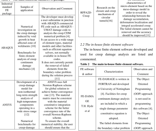
Fig. 1 The structure of developing new FE software.
The steps for the development of finite element software can be summarized in:
1. Input the definition of a specific FE model including nodes, element, material property, boundary condition, as well as the computational control parameters
2. Calculate the initial elastic stress and strain 3. Integrate the constitutive equation and update the field variables such as creep strain, damage, stress; the time step is controlled
4. Remove the failed element [17] and update the stiffness matrix
5. Stop execution and output results
3.2 The equilibrium equations
Assume that the total strain ε can be partitioned into
the elastic and creep strains, thus the total strain increment can be expressed as:
∆ε = ∆εe + ∆εc (1)
Where ∆ε, ∆εe and ∆εc are increments in total, elastic and creep strain components, respectively [22].
The stress increment is related to the elastic and creep strain increments by:
∆σ = D (∆ε - ∆εc) (2)
Where D is the stress-strain matrix and it contains the elastic constants.
The stress increments are related to the incremental displacement vector ∆u by:
∆σ = D (B ∆u - ∆εc ) (3)
Where B is strain matrix. The equilibrium equation to be satisfied any time can be expressed by:
∫ v BT∆σ dv = ∆R (4)
Where ∆R is the vector of the equivalent nodal mechanical load and v is the element volume. Combining equations (3) and (4):
∫ v BT D (B ∆u - ∆εc ) dv = ∆R (5)
3.3 Sample creep damage constitutive equations
The creep damage constitutive equations are proposed to depict the behaviors of material during creep damage (deformation and rupture) process, especially for predicting the lifetime of material. One example is Kachanov-Rabatnov-Hayhurst (KRH) constitutive equations which is popular and is introduced here [23].
− Uni-axial form
6.1
∗ 6.2
! " 6.3
$∗ 6.4
(6)
Where A, B C, h, H* and Kc are material parameters. H (0<H< H*) indicates strain hardening during primary creep, φ (0< φ < 1) describes the evolution of spacing of the carbide precipitates [23].
[image:4.595.55.283.91.442.2]
&' !(*)+ + 7.1
+
∗ 7.2
! " 7.3
+ 〈+〉/ 7.4
(7)
Where 01 is the Von Mises stress, 02 is the maximum principal stress and ν is the stress state index defining the multi-axial stress rupture criterion [23].
The intergranular cavitation damage varies from zero, for the material in the virgin state, to 1/3, when all of the grain boundaries normal to the applied stress have completely cavitated, at which time the material is considered to have failed [24]. Thus, the critical value of creep damage is set to 0.3333333 in the current program. Once the creep damage reaches the critical value, the program will stop execution and the results will be output automatically. Other type of creep damage constitutive equations will be incorporated in the FE software in future.
3.4 The integration scheme
The FEA solution critically depends on the selection of the size of time steps associated with an appropriate integration method. Some integration methods have been reviewed in previous work [3]. In the current version, Euler forward integration subroutine, developed by colleagues [25], was adopted here for simplicity.
4 + ∗ ∆7 8.1
4 + ∗ ∆7 8.2
4 + ∗ ∆7 8.3
4 + ∗ ∆7 8.4
74 7+ ∆7 8.5
(8)
It is noted that D02BHF (NAG) [26] integrates a system of first-order ordinary differential equations solution using Runge-Kutta-Merson method. This subroutine can be adopted in the FEA software of creep damage analysis development, and a detailed instruction on how to use it was published by the
company [26]. A more sophisticated Runge-Kutta type integration scheme will be adopted and explored in future.
3.5 The finite element algorithm for updating stress
The Absolute Method [27] has been given for the solution of the structural creep damage problems. The principle of virtual work applied to the boundary value problem is given:
Pload= [Kv] * TOTD – P c (9)
Where Pload is applied force vector, and [Kv] is the
global stiffness matrix, which is assembled by the element stiffness matrices [Km]; TOTD is the global
vector of the nodal displacements and P c is the global creep force vector.
[Km] = ∫∫ [B] T
[D] [B] dxdy (10)
The [B] and [D] represent the strain-displacement and stress-strain matrices respectively.
TOTD = [Kv] -1
* (Pload + P c) (11)
The initial P c is zero and the Choleski Method [27] is used for the inverse of the global stiffness matrix [Kv]. By giving the Pload, the elastic strain εek and the
elastic stress σek for each element can be obtained:
εek= [B] * ELD (12) σek = [D] * ε (13)
The element node displacement ELD can be found from the global displacement vector and the creep strain rate εckrate for each element can be obtained by substituting the element elastic stress into the creep damage constitutive equations. The creep strain can be calculated as:
εck ( t + △△△△t ) = εcK( t ) + εcKrate * △△△△t (14)
The node creep force vectors for each element are given by:
Pck = [B] T
[D] * εcK (15)
The node creep force vector Pck can be assembled into the global creep force vector P c and the P c is used to up-date equation (9). Thus, the elastic strain can be updated:
Where the εtotk and εck represent the total strain and creep strain for each element respectively; and the elastic strain εek is used to up-date the equation (13).
3.6 The standard FE library and subroutines
In the development of this software, the existing FE library and subroutines such as [27] were used in programming. The subroutines can perform the tasks of finite element meshing, assemble element matrices into system matrices and carry out appropriate equilibrium, eigenvalue or propagation calculations. Some subroutines used in programming are reviewed in Table 3.
Table 3 The existing FE library and subroutines.
The standard subroutine Function
Subroutine geometry_3tx To form the coordinates and node vector for a rectangular mesh of
uniform 3-node triangles Subroutine formkb and
Subroutine formkv
To assemble the individual element matrices to form the
global matrices Subroutine sparin and
Subroutine spabac
To solve the sets of linear algebraic equations based on the Cholesky direct solution method
4. Preliminary Validation and Discussion
4.1 The validation of plane stress problem
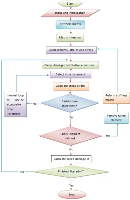
The validation of new software for plane stress was performed and it was conducted via a two- dimensional tension model. The length of a side is set to 1 meter. The Young's modulus E and Poisson's ratio υ are set to 1000MPa and 0.3 respectively. A uniformly distributed linear load 40KN/m was applied on the top line of this uni-axial tension model.
Fig. 2 2D plane stress tension mode.
The theoretical stress in Y direction is 40KN/m2. The stress in X direction should be zero. These stress values should remain the same throughout the creep test up to failure.
Samples of the stress obtained from FE software with the stress updating invoked due to creep deformation are shown in Figure 3 and Figure 4.
Fig. 3 The stress distribution in Y direction at rupture time.
Fig. 4 The stress distribution in X direction at rupture time.
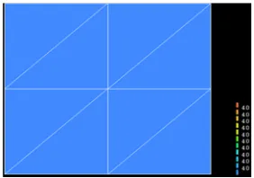
Using the theoretical stress value into the uni-axial version of creep constitutive equations and a 0.1 hour time step with Euler forward integration method, the theoretical rupture time, creep strain rate, creep strain and damage can be obtained by a excel program [28] and some of them are shown in Table 4.
Table 4 The results obtained from excel program
Rupture time Creep strain Creep damage
104062 0.179934333 0.33333335
[image:6.595.353.494.230.329.2] [image:6.595.51.294.304.464.2] [image:6.595.353.494.386.486.2] [image:6.595.115.238.627.737.2] [image:6.595.300.545.648.681.2]integration method, the rupture time, creep strain rate, creep strain and damage obtained from FE software at failure were obtained and are shown in Table 5. Table 5 The results obtained from FE software for plane stress problem Element number Rupture time Strain rate Creep strain Creep damage Element No.1 0.1040E+ 06 0.6540E -04 0.1798E+ 00 0.3334E +00 Element No.2 0.1040E+ 06 0.6540E -04 0.1798E+ 00 0.3334E +00 Element No.3 0.1040E+ 06 0.6540E -04 0.1798E+ 00 0.3334E +00 Element No.4 0.1040E+ 06 0.6540E -04 0.1798E+ 00 0.3334E +00 Element No.5 0.1040E+ 06 0.6540E -04 0.1798E+ 00 0.3334E +00 Element No.6 0.1040E+ 06 0.6540E -04 0.1798E+ 00 0.3334E +00 Element No.7 0.1040E+ 06 0.6540E -04 0.1798E+ 00 0.3334E +00 Element No.8 0.1040E+ 06 0.6540E -04 0.1798E+ 00 0.3334E +00
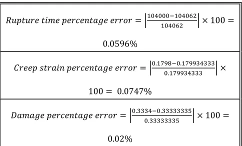
The percentage errors of FE results against theoretical results are shown in Table 6.
Table 6 The percentage errors
;<=><?@ >AB@ =@?C@D>EF@ @??G? H2IJIII2IJIKL2IJIKL H M 100
0.0596%
Q?@@= R>?EAD =@?C@D>EF@ @??G? HI.2STUI.2STTVJVVVI.2STTVJVVV H M
100 0.0747%
WEBEF@ =@?C@D>EF@ @??G? HI.VVVJI.VVVVVVVXI.VVVVVVVX H M 100
0.02%
A comparison of the results shown in Table 4 and Table 5 and an examination of the percentage errors shown in Table 6 clearly show the results obtained from the FE software do agree with the expected
theoretical values and the percentage errors are negligible.
In the current version, Euler forward integration subroutine, developed by colleagues [25] was adopted here. Rupture time, strain rate, creep strain and damage obtained from FE software have been revealed that the FE results have a good agreement with the theoretical values.
4.2 The validation of plane strain problem
The validation of this software for plane stress was performed and it was conducted via a uni-axial tension model. The width of this model is set to 5 meters. The Young's modulus E and Poisson's ratio υ are set to 1000 MPa and 0.3 respectively. A uniformly linear distributed load 10 KN/m was applied on the top line of this model.
Fig. 5 Plane strain tension model.
The theoretical stress in Y direction can be shown as:
YZ 5.0 10 [\/B50 L
The theoretical stress in Z direction can be shown as:
^ _ ∗ `^ _ ∗ a ∗ `Y _ ∗ a ∗_ 3[\/BY L
[image:7.595.51.291.164.449.2] [image:7.595.368.475.354.489.2] [image:7.595.52.294.508.654.2]Fig. 6 Stress distribution in Y direction at rupture time.
Fig. 7 Stress distribution in Z direction at rupture time.
Fig. 8 Displacement distribution in Y axis at rupture time.
Fig. 9 Displacement distribution in X axis at rupture time.
Using the theoretical stress value into the
multi-axial version of creep constitutive equations, the theoretical rupture time and damage can be obtained without stress update by a testified subroutine [25] and the results are shown in Table 7.
Table 7 The theoretical rupture time and creep damage for plane strain case
Rupture time Creep damage
180460 0.3333334
The damage obtained from FE software at failure.
Fig. 10 The damage distribution on 180230h.
The Figure 6 and Figure 7 show the results obtained from the FE software do agree with the expected theoretical values.
The displacement is distributed reasonable in Figure 8 and Figure 9. Table 7 and Figure 10 have revealed that rupture time and damage obtained from FE software have a good agreement with the theoretical values obtained from the subroutine [29].
4.3 The validation of axisymmetric problem
[image:8.595.126.219.87.208.2] [image:8.595.124.221.245.362.2] [image:8.595.375.482.246.366.2] [image:8.595.123.222.402.518.2] [image:8.595.124.219.558.672.2]Fig. 11 The axisymmetric FE model.
Using the theoretical stress value into the multi-axial version of creep constitutive equations and a 0.1 hour time step with Euler forward integration method, the theoretical rupture time and damage can be obtained by a subroutine [29] and the results are shown in Table 8.
Table 8 The theoretical rupture time and creep damage for axisymmetric case
Rupture time Creep damage
146080 0.3333334
The stress and displacement obtained from FE software with the stress updating invoked due to creep deformation are shown in Figure 12 and Figure 13.
Fig. 12 Displacement distribution in Z axis.
Fig. 13 The displacement distribution in r axis.
Fig. 14 Stress distribution in Z direction.
Fig. 15 Damage distribution on 143060h.
The stress has been uniformly distributed in Figure 14 and do agree with the theoretical values.
Other results are shown in Table 8 and Figure 15. Rupture time and damage obtained from FE software have been revealed that have a good agreement with the theoretical values obtained from the subroutine [29].
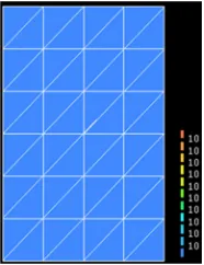
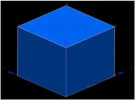
4.4 The validation of 3D problem
A preliminary validation of such software was performed and it was conducted via a three- dimensional uni-axial tension model given below. The length of a side is set to 1 meter and a uniformly distributed load 5KN was applied on the top surface of this uni-axial tension model.
Fig. 16 The three-dimensional uni-axial tension model.
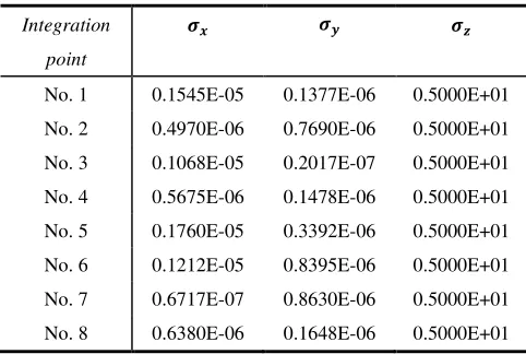
[image:9.595.347.501.90.174.2] [image:9.595.69.269.90.185.2] [image:9.595.341.501.215.300.2] [image:9.595.97.246.451.536.2] [image:9.595.356.493.573.674.2] [image:9.595.94.248.576.662.2]stress in X and Y direction should be zero and these stress values should remain the same throughout the creep test up to failure. The stress obtained from FE software with the stress update program is shown in Table 9 at a 0.1 hour time step with Euler forward integration method.
Table 9 The stress obtained from FE software with the stress update program
Integration
point
b Y ^
No. 1 0.1545E-05 0.1377E-06 0.5000E+01 No. 2 0.4970E-06 0.7690E-06 0.5000E+01 No. 3 0.1068E-05 0.2017E-07 0.5000E+01 No. 4 0.5675E-06 0.1478E-06 0.5000E+01 No. 5 0.1760E-05 0.3392E-06 0.5000E+01 No. 6 0.1212E-05 0.8395E-06 0.5000E+01 No. 7 0.6717E-07 0.8630E-06 0.5000E+01 No. 8 0.6380E-06 0.1648E-06 0.5000E+01
Table 9 shows the results obtained from the FE software do agree with the expected theoretical values. The stress involving creep deformation and stress updating confirmed the uniform distribution of stresses, and the values of stress in Z direction obtained from FE software are correct, and the stress in X and Y direction is negligible.
[image:10.595.51.292.208.370.2]The lifetime and creep strain at failure, and other field variable can be obtained for the simple tensile case illustrated above. They have been obtained by direct integration of the uni-axial version of constitutive equation for a given stress [30]. They have also been produced by the FE software. Table 10 is a summary and comparison of them.
Table 10 The stress obtained from FE software with the stress update program
The results Theoretical value FE results
Rupture time 98046 93540
Strain rate 0.000065438 0.000067522 Creep strain 0.179934333 0.182658312
Damage 0.33333337 0.33333334
Table 10 reveals that real values have a good agreement with the theoretical values obtained from the subroutine [30]. Work in this area is ongoing and will be reported in future.
5. Conclusion
This paper is to present the finite element method based on CDM to design FE software for creep damage mechanics. More specifically, it summarizes the current state of how to obtain such computational capability then it concludes with a preference of in-house software; secondly, it reports the development of such software including the development of finite element algorithms based on CDM for creep damage analysis, and a flow diagram of the structure of new finite element software has been completed to be guided in developing in-house FE software, and the use of some standard subroutines in programming; thirdly, the development and the validation of the finite element software conducted so far include plane stress, plane strain, axisymmetric case, and 3D case were reported.
Working in this area is ongoing and future development work includes: 1) development and incorporation the new constitutive equation subroutines; 2) intelligent and practical control of the time steps; 3) removal of failed element and update stiffness matrix; and 4) further validation. Further real case study to be conducted and reported.
References
[1] J. Lemaitre, J.L. Chaboche, Mechanics of Solid Materials, Cambridge University Press, 1st ed. Cambridge, 1994.
[image:10.595.51.292.632.717.2][4] A.A. Becker, T.H. Hyde, W. Sun, P. Andersson, Benchmarks for finite element analysis of creep continuum damage mechanics, Computational Materials Science 25 (2002) 34-41.
[5] D.R. Hayhurst, A.J. Krzeczkowski, Numerical solution of creep problems, Comput. Methods App. Mech. Eng 20 (1979) 151-171.
[6] X. Ling, S.T. Tu and J.M. Gong, Application of Runge-Kutta-Merson algorithm for creep damage analysis, International Journal of Pressure Vessels and Piping 77 (2000) 243-248.
[7] Q. Xu, Creep damage constitutive equations for multi-axial states of stress for 0.5Cr0.5Mo0.25V ferritic steel at 590°C, Theoretical and Applied Fracture Mechanics 36 (2001) 99-107.
[8] L. An, Q. Xu, D. Xu, Z. Lu, Review on the Current State of Developing of Advanced Creep Damage Constitutive Equations for High Chromium Alloy, Advanced Materials Research 510 (2012) 776-780. [9] Q.H. Xu, Q. Xu, Y.X. Pan, M. Short, Current state of developing creep damage constitutive equation for 0.5Cr0.5Mo0.25V ferritic steel, Advanced Materials Research 510 (2012) 812-816.
[10] Y. Tao, Y. Masataka, H.J. Shi, Numerical investigation on the creep damage induced by void growth in heat affected zone of weldments, International Journal of Pressure Vessels and Piping 86 (2009) 578-584.
[11] R. Mustata, R.J. Hayhurst, D.R. Hayhurst, F. Vakili-Tahami, CDM predictions of creep damage initiation and growth in ferritic steel weldments in a medium-bore branched pipe under constant pressure at 590°C using a four-material weld model, Arch Appl Mech 75 (2006) 475-495.
[12] M.S. Herrn, G. Yevgen, Development of a creep-damage model for non-isothermal long-term strength analysis of high-temperature components operating in a wide stress range, ULB Sachsen-Anhalt, 2008.
[13] A. Holm, N. Konstantin, G. Yevgen, Numerical benchmarks for creep-damage modelling, Proceeding in Applied Mathematics and Mechanics, 2008.
[14] H. Altenbach, G. Kolarow, O.K. Morachkovsky, K. Naumenko, On the accuracy of creep-damage predictions in thinwalled structures using the finite element method, Computational Mechanics 25 (2000) 87-98.
[15] M. Klasztorny, A. Bondyra, P. Szurgott, D. Nycz, Numerical modelling of GFRP laminates with MSC.Marc system and experimental validation”, Computational Materials Science 64 (2012) 151-156.
[16] H.C. Li, C.A. Tang, T.H. Ma, X.D. Zhao, Research on the closure and creep mechanism of circular tunnels,
Journal of Coal Science and Engineering 14 (2008) 195-199.
[17] M.T. Wong, Three-Dimensional Finite Element Analysis of Creep Continuum Damage Growth and Failure in Weldments, PHD thesis, University of Manchester, UK, 1999.
[18] D.R. Hayhurst, R.J. Hayhurst, F. Vakili-Tahami, Continuum damage mechanics predictions of creep damage initiation and growth in ferritic steel weldments in a medium-bore branched pipe under constant pressure at 590°C using a five-material weld model, PROC. R. SOC. A 461 (2005) 2303-2326.
[19] R.J. Hayhurst, F. Vakili-Tahami, D.R. Hayhurst, Verification of 3-D parallel CDM software for the analysis of creep failure in the HAZ region of Cr-Mo-V crosswelds, International Journal of Pressure Vessels and Piping 86 (2009) 475-485.
[20] K. Naumenko, H. Altenbach, Modeling of Creep for Structural Analysis, Springer Berlin Heidelberg New York, 2004, pp. 1612-1384.
[21] F. Dunne, J. Lin, D.R. Hayhurst, J. Makin, Modelling creep, ratchetting and failure in structural components subjected to thermo-mechanical loading, Journal of Theoretical and Applied Mechanics 44 (2006) 87-98.
[22] F.A. Leckie, D.R. Hayhurst, Constitutive equations for creep rupture, Acta Metallurgical 25 (1977) 1059-1070.
[23] D.R. Hayhurst, P.R. Dimmer, G.J. Morrison, Development of continuum damage in the creep rupture of notched bars, Trans R Soc London A 311 (1984) 103-129.
[24] I.J. Perrin, D.R. Hayhurst, Creep constitutive equations for a 0.5Cr–0.5Mo–0.25V ferritic steel in the temperature range 600–675°C, J. Strain Anal. Eng 31 (1996) 299-314.
[25] F. Tan, Q. Xu, Z. Lu, D. Xu, The preliminary development of computational software system for creep damage analysis in weldment, Proceedings of the 18th International Conference on Automation & Computing, 2012.
[26] The NAG Fortran Library, Mark 23, The Numerical Algorithms Group Ltd, Oxford, UK.
[27] I.M. Smith, D.V. Griffiths, Programming the Finite Element Method, John Wiley & Sons Ltd., 4th ed. Sussex, 2004.
[28] Q. Xu, M. Wright, Q.H., Xu, The development and validation of multi-axial creep damage constitutive equations for P91, ICAC'11: The 17th international conference on automation and computing, 2011.
finite element analysis of creep damage, The 2013 World Congress in Computer Science, Computer Engineering, and Applied Computing, 2013.