© 2016, IRJET |
Impact Factor
value
: 4.45|
ISO 9001:2008 Certified Journal | Page 833
Analysis of two wheeler suspension Spring by Using FEA for Different
Materials
Sagar Namdev Khurd, Prasad P Kulkarni, Samir D Katekar ,Arvind M Chavan
1
Department of mechanical Engineering, Sveri’s College of Engineering, Pandharpur,
2
Department of mechanical Engineering, SKN Sinhgad College of Engineering, Korti, Pandharpur ,
3
Department of mechanical Engineering, SKN Sinhgad College of Engineering, Korti, Pandharpur ,
---***---Abstract
-The present work is carried out on modeling, analysis and testing of suspension spring (helical coil spring) is to replaced by different material for two wheeler vehicle. The stress and deflections of the helical spring is going to be reduced by using the new material. The comparative study is carried out between existed spring and new material spring. Static analysis in FEA (workbench) determines the stress and deflections of the helical compression. Finite element analysis methods (FEA) are the methods of finding approximate solutions to a physical problem defined in a finite region. FEA (workbench) is a mathematical tool for solving engineering problems. In this the finite element analysis values are with different materials. A typical two wheeler helical compression spring is chosen for study. The modeling and analysis is carried out on ANSYS 14.
Keywords: - helical compression spring, stress, deflection, analysis, ANSYS 14 (Workbench)
INTRODUCTION
A spring is defined as an elastic body, whose function is to distort when loaded and to recover its original shape when the load is removed. This paper demonstrates by taking the combination of steel and composite material for design of helical compression spring. In this case instead of steel is used combination of steel and composite material Glass fiber/Epoxy because of low stiffness of single composite spring, which limits its application to light weight vehicle only. Composite material is light weight and corrosion resistance, it can withstand high temperature. It increase efficiency of vehicle and overcome the cost. He had concluded combination of steel and composite material can increase the stiffness which is the major requirement of regular vehicle due to higher weight this done by using the FEA.[1].This study investigates static behavior of helical structure under axial loads. In this paper, authors have taken two helical structure first one is single wire on which homogeneous theory applied and second is axial elastic properties of
seven wire strand are computed. This approach, based on asymptotic expansion, gives the first-order approximation of the 3D elasticity problem from the solution of a 2D microscopic problem posed on the cross-section and a 1D macroscopic problem, which turns out to be a Navier– Bernoulli–Saint-Venant beam problem and result compared with reference results.[2] This paper researchers taken four composite material (structure)these are unidirectional laminates (AU), rubber core unidirectional laminates (UR), Unidirectional laminates with braided outer layer (BU), and rubber core unidirectional laminates with braided outer layer (BUR). They investigated effect of rubber core and braided outer layer on the mechanical properties of the above mentioned helical springs. According to the experimental results, the helical composite spring with a rubber core can increase its failure load in compression by about 12%; while the spring with a braided outer layer cannot only increase its failure load in compression by about 18%, but also improve the spring constant by approximately 16%. [3]This study deals with the stress analysis of a helical coil compression spring, which is employed in three wheeler’s auto-rickshaw belonging to the medium segment of the Indian automotive market. This spring’s have to face very high working stresses, so in this design of the spring both the elastic characteristics and the fatigue strength have to be considered as significant aspects. This done by using finite element analysis. These springs have to face very high working stresses. The structural reliability of the spring must therefore be ensured. [4]
© 2016, IRJET |
Impact Factor
value
: 4.45|
ISO 9001:2008 Certified Journal | Page 834
II .Finite element analysis of helical spring
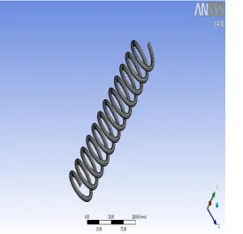
[image:2.595.333.565.126.276.2]Analysis has been carried out in ANSYS work bench. Constrained spring geometry is as shown in figure 2.1.
Fig.2.1 Geometry of the spring in ANSYS
Geometry is meshed by using brick element. Total number of nodes 24620 and elements 4950 are generated after meshing. One end of the spring is fixed in all direction while load is applied in Y direction at another end. It is shown in figure 2.2
[image:2.595.36.295.157.357.2]Fig.2.2 Meshed model of helical coil spring
[image:2.595.341.565.346.621.2]Table No.1 Input parameters for Analysis of spring
Table No.2 Material properties of spring for analysis (Epoxy)
Table 2.1 shows material properties in X, Y and Z directions which are used for analysis.
Sr.No. Parameters Values
1 Height(mm) 225
2 Wire diameter(mm) 6
3 Turns(mm) 12
4 Coil diameter(mm) 30
5 Force (N) 1000
Sr.
No. Material Property Value
1 Young’s modulus (EX), MPa 34000
2 Young’s modulus ((EY) MPa 6530
3 Young’s modulus (EZ) MPa 6530
4 Shear modulus along
XY-direction (Gxy), MPa 2433
5 Shear modulus along
XY-direction (Gyz), MPa 1698
6 Shear modulus along
XY-direction (Gzx), MPa 2433 7 Force on x direction, N 1000
8 Poisson ratio along
XY-direction (NUxy) 0.217
9 Poisson ratio along
YZ-direction (NUyz 0.366
10 Poisson ratio along
[image:2.595.42.521.436.737.2] [image:2.595.39.315.463.727.2]© 2016, IRJET |
Impact Factor
value
: 4.45|
ISO 9001:2008 Certified Journal | Page 835
Table No.3 Spring properties for different materials
As shown in the table No.2.4. For analysis of helical coil spring above properties are taken into considerations.
III .RESULTS AND DISCUSSION
1. Finite element results
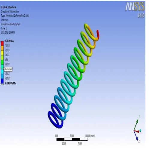
[image:3.595.309.575.315.501.2]In this chapter, analysis of helical coil spring by using the FEA (WORKBENCH) has been discussed. This analysis provides the results and under the loading condition, compression strength of helical coil spring is obtained. Stress distribution of helical coil spring is as shown below in figure 3.1.In this case, static analysis is done by using the finite element method, in the figure blue color indicates the minimum stresses 4.8243E6 acting on the turns and red color indicates maximum stresses 4.7278E9.
[image:3.595.38.287.468.718.2]Fig.3.1. Equivalent stress of helical coil spring
Fig.3.2. Total deformation of helical coil spring
Fig.3.3. Maximum shear stress of helical coil spring Figure shows maximum shear stress, deformation and von mises stresses of helical compression spring. Sr. No. Material Nominal Analysis Elasticity (E) Modulus of
Max. Operating
Temp. (C)
Modulus Rigidity
(G)
1 Oil Tempered Carbon Steel Mn 0.60-1.30% C: 0.45-0.85%, 20700 150 79000
2 Epoxy -
3 Vanadium Chrome steel Cr 0.80-1.10%, C 0.48-0.53%,
V 0.15 min % 20700 220 79300
[image:3.595.306.564.536.726.2]© 2016, IRJET |
Impact Factor
value
: 4.45|
ISO 9001:2008 Certified Journal | Page 836
2. Analysis of spring by FEA (Oil Tempered
Carbon Steel)
Table No.4 Load verses Max. Shear stress
Load Maximum Shear Stress
For Oil Tempered
Carbon Steel(N/mm2)
Deflection (mm)
500 345.56 130.89
600 427.51 146.8
700 507.48 165.41
800 582.33 197.53
900 621.5 202.97
[image:4.595.34.568.82.692.2]1000 648.81 206.91
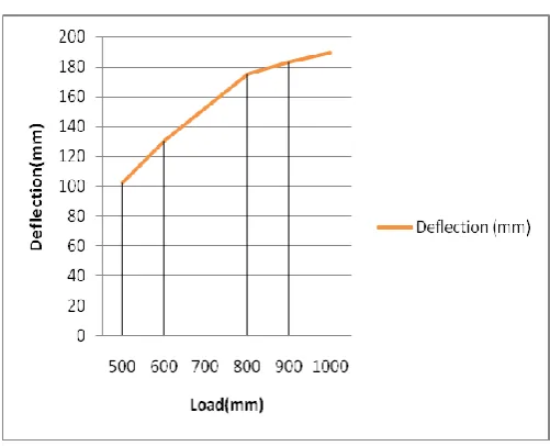
[image:4.595.304.566.100.421.2]Fig. No.3.4 Load verses Max. Shear stress
Fig. No.3.5 Load verses deflection
As shown in figure the load verses Max. shear stress, If load increases the deflection increases and vice versa.
Table No.4 Load verses Max. Shear stress and Deflection
Load(N) Maximum Shear
Stress for
Epoxy(N/mm2)
Deflection (mm)
500 241.929 102.36
600 262.92 130.49
700 325.788 152.28
800 342.801 174.98
900 425.76 182.92
[image:4.595.308.559.440.643.2]1000 454.68 189.38
Fig. No.3.6 Load verses Max. Shear stress
Fig. No.3.7 Load verses deflection
© 2016, IRJET |
Impact Factor
value
: 4.45|
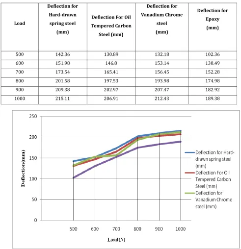
ISO 9001:2008 Certified Journal | Page 837 Table No.5 Load verses Deflection
Load
Deflection for Hard-drawn
spring steel (mm)
Deflection For Oil Tempered Carbon
Steel (mm)
Deflection for Vanadium Chrome
steel (mm)
Deflection for Epoxy
(mm)
500 142.36 130.89 132.18 102.36
600 151.98 146.8 153.14 130.49
700 173.54 165.41 156.45 152.28
800 201.58 197.53 193.98 174.98
900 209.38 202.97 207.47 182.92
1000 215.11 206.91 212.43 189.38
Fig. No.3.8 Load verses Deflection
© 2016, IRJET |
Impact Factor
value
: 4.45|
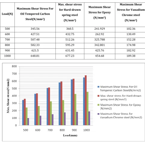
ISO 9001:2008 Certified Journal | Page 838 Table No.6 Load verses Maximum Shear Stress
Load(N)
Maximum Shear Stress For Oil Tempered Carbon
Steel(N/mm2)
Max. shear stress for Hard-drawn
spring steel
(N/mm2)
Maximum Shear Stress for Epoxy
(N/mm2)
Maximum Shear Stress for Vanadium
Chrome steel
(N/mm2)
500 345.56 360.5 241.929 102.36
600 427.51 432.75 262.92 130.49
700 507.48 512.26 325.788 152.28
800 582.33 595.29 342.801 174.98
900 621.5 631.45 425.76 182.92
1000 648.81 677.23 454.68 189.38
Fig. No.3.8 Load verses Max. shear stress
A graph is plotted as shown in Fig. 5.18 between load verses maximum shear stress of four different materials. Load is taken on the X - axis and max. shear stress taken on the Y - axis. It is seen in 5.17 graphs that, when load increases the shear stress increases linearly. Shear stresses on E-glass/epoxy are less than other as shown in fig. The E-glass fiber is a high quality glass, which is used as standard reinforcement fiber for all the present systems well complying with mechanical property requirements. Thus, E-glass fiber was found appropriate for this application.
IV. CONCLUSION - The comparative study has been carried out in between
© 2016, IRJET |
Impact Factor
value
: 4.45|
ISO 9001:2008 Certified Journal | Page 839
-It is observed that force and material property are significant parameters which affect compressive strength of helical coil spring.
-Finite element analysis of helical coil spring has been carried out.
-The maximum shear stress of Epoxy spring has 15-19% less with compare to hard drawn steel spring, chrome vanadium steel and oil tempered carbon steel.
-The deflection pattern of the Epoxy spring 15% less at same weight with compare to other three materials.
REFERENCES
[1] Saurabh Singh- “Optimization of Design of Helical Coil Suspension System by Combination of Conventional Steel and Composite Material in Regular Vehicle” International Journal of Applied Engineering Research, ISSN 0973-4562 Vol.7 No.11 (2012)
[2].Ahmed Frikha, Patrice Carried, Fabien Trussed “Mechanical modeling of helical structures accounting for translational invariance. Part 1: Static behavior/ Frikha et al. / International Journal of Solids and Structures 50 (2013) 1373–138
[3].Chang-Hsuan Chiu , Chung-Li Hwan , Han-Shuin Tsai , Wei-Ping Lee An experimental investigation into the mechanical behaviors of helical composite springs C.-H. Chiu et al. / Composite Structures 77 (2007) 331–340 [4].Tausif M. Mulla1, Sunil J. Kadam2, Vaibhav S. Kengar3, “Finite Element Analysis Of Helical Coil Compression Spring For Three Wheeler Automotiv Front Suspension”,
International Journal Of Mechanical and Industrial Engineering (IJMIE) ISSN No. 2231 –6477, Vol-2, Iss-3, 2012
[5].Becker L.E., G.G.Chasssies:- “ On the Natural frequencies of helical compression springs” L.E. Becker et al. / International Journal of Mechanical Sciences 44 (2002) 825–841
[6].B. Pyttel, I.Brunner, B. Kaiser, C.Berger, Mahendran, “Fatigue behaviour of helical compression springs at a very high number of cycles .Investigation of various influences B. Pyttel et al. / International Journal of Fatigue (2013)
[7] Sagar N Khurd, Prasad P Kulkarni, Samir D Katekar , “Probabilistic design of helical coil spring for Translational invariance by using Finite Element Method” International Research Journal of Engineering and Technology (IRJET) e-ISSN: 2395 -0056 Volume: 02 Issue: 06 Se2015 p-ISSN: 2395-0072