International Journal of Emerging Technology and Advanced Engineering
Website: www.ijetae.com (ISSN 2250-2459,ISO 9001:2008 Certified Journal, Volume 3, Issue 10, October 2013)
716
Performance & Comparison Analysis of Indirect Vector
Control of Three Phase Induction Motor
Rakesh Singh Lodhi
1, Payal Thakur
2 1,2Department of Electrical & Electronic Engineering, Vindhya Institute of Technology & Science Indore(M.P.), India
Abstract-- The objective of this paper to provide the precise solution for speed control of three phase induction motor for high speed variable speed drives. In this paper, Implementation of indirect vector control induction motor drive has been developed, which provide quick torque & good dynamic responses near zero speed & high speed. The simulation result of IVCIMD shows four quadrant operation of drive. The performance of indirect vector control induction motor drive is enhanced using different controller & comparative performance has been presented & analysed in this work. This paper also present different speed control methods of induction motor. In addition, MATLAB code results for variable stator voltage, variable rotor resistance, constant Volts/Hz control & variation of direct-axis stator current, quadrature-axis stator current with variation in stator voltage is also present & comparative study has been made between us.
Keywords-- Indirect Vector Control Induction Motor Drive (IVCIMD), Stationary Reference Frame, Open Loop Control, Synchronous Rotating Reference Frame, Variable Speed Drives.
I. INTRODUCTION
Electric drive has evolved over the year & so have the techniques to control their speed & torque. There are a large number of researches activities taking place in order to achieve stable control techniques with growing capabilities in similar fields, the control techniques are also become better with time.
In 1980s, DC motor drives were generally used in variable speed drives because of the simplicity of control due to decoupling between armature current & the field current. But DC motor has several disadvantages such as regular maintaince of commutator, brushes & brushes holder, limited current carrying capacity during high speed applications etc. Therefore squirrel cage induction motor are widely used as they have highly reliable, robust construction & free from regular maintaince & become work horses in the industry for the variable speed application in a wide power range. This is the main reason to replace the DC motor with an induction is to merge the advantage of both motor together into a variable speed drives & eliminate the associate problem. These applications include pumps & fans, paper mill, subway & locomotive propulsions, electric & hybrid vehicles, machine tools & robotics, home appliances, heat pumps etc.
The control & estimation of ac drives in general is considered more complex than those of dc drives, & this complexity increase substantially if performance are demanded.[1][20]
To control the induction motor there are different types of control are there they are:
Variable supply voltage control
Variable rotor resistance control
Constant Volts/Hz control (scalar
control)
Direct torque control
Vector Control
II. SPEED CONTROL METHOD OF INDUCTION MOTOR
A. Variable Rotor Resistance control
In this method of speed control an resistances can be connected in the rotor circuit externally during starting. At starting slip s =1, this increases the starting torque and reduces the starting current. The maximum torque during starting can be achieved by using appropriate value of resistors. Once the motor is started acceleration, the resistance can be connect externally should be cut out to obtain high torque throughout the accelerating range. As external resistances are connected, most of the I2R loss is dissipated through them thus the rotor temperature rise during starting is limited. This method can be used in applications requiring high starting torque. This method is used only for wound motor, an external resistance is added to it through slip rings. [36][67]
B. Variable Stator Voltage
The developed torque of an induction motor is proportional to square of the supply voltage to its stator
terminals, by varying the supply voltage, the
International Journal of Emerging Technology and Advanced Engineering
Website: www.ijetae.com (ISSN 2250-2459,ISO 9001:2008 Certified Journal, Volume 3, Issue 10, October 2013)
717
C. Scalar control (constant v/f control)
The name scalar (constant v/f) control indicates the variation of magnitude of control variables only. The control of an induction motor requires a variable voltage, variable frequency three phase source. With advent of the voltage source inverter (VSI), constant voltage/hertz (scalar) control has become the simplest & cheapest popular methods of speed control of induction motor.
The principle of v/f control is that, the base speed of induction motor is proportional to the supply frequency so, the best way of vary the speed of induction motor by varying the frequency of supply. The developed torque of motor is directly proportional to the ratio of the supply voltage & frequency. So the main aim to maintaining the same terminal voltage to frequency ratio constant so as to torque developed can be kept constant give constant flux over a wide range of speed variation. Since the flux is kept constant, full load torque capability are maintained constant under steady state condition except low speed. [70]
In this control scheme, the performance of induction motor improves in the steady state only, but the transient state response is poor. More over Constant voltage/hertz (scalar) control keeps the stator flux linkage constant in steady state without maintaining the decoupling between flux and torque. So the dynamic response of the drive is poor due to inherent coupling effect. These foregoing problems can be solved by vector control or field oriented control. [37]
D. Vector control
The vector control scheme is being invented in 1970s, and its demonstrate that an induction motor (Ac motor) can be controlled like a separately excited dc motor, brought a renaissance in the high speed performance control of ac drives. The vector control is also known as decoupling, orthogonal, or transvector control because of the separately excited dc motor like performance. The vector control is applicable to both induction and synchronous motor drives. There are two methods of vector control, Direct or feedback method &Indirect or feed forward method [9].
In direct vector control method, directly measures the rotor flux & using that flux to determine the transformation angle. This method also called as open loop vector control. Direct measurement of flux is physically difficult, so estimated value of flux is calculated using stator voltages & currents value. At higher speed, value of estimated flux may be reliable but at lower speed, this is subjected to errors from harmonics.[39]
The direct method of vector control attempts to directly measure or estimate the machine flux, and use this to determine the transformation angle. While direct flux measurements are difficult physically, an estimate value of flux is calculated using the stator voltages and currents equations. At the higher speed ranges, the flux estimate may be reliably estimated from the integral of the stator voltage. However, this method is subject to errors from harmonics, and is not useful at lower speeds. Due to the difficulty in reliably obtaining an estimate of the rotor flux direction, the direct method of vector control is not commonly used. Instead, the indirect method has gained popularity. [1][41]
III. PRINCIPLE &BLOCK OF INDIRECT VECTOR
CONTROL OF INDUCTION MOTOR
Blaschke in 1972, has introduced the principle of vector control of induction motor, to realize the characteristics of d.c motor in an induction motor drive. In vector control, both flux & torque are control independently i.e both are decoupled in nature.
An a.c machine is not simple because of the interaction between stator & rotor field, whose orientation is not held at 90 degree but vary with operating conditions. We can obtain d.c machine like performance, by considering the induction motor in synchronous rotating reference frame. Where all sinusoidal variables appear like d.c quantity in steady state.
International Journal of Emerging Technology and Advanced Engineering
Website: www.ijetae.com (ISSN 2250-2459,ISO 9001:2008 Certified Journal, Volume 3, Issue 10, October 2013)
[image:3.595.52.290.133.415.2]718
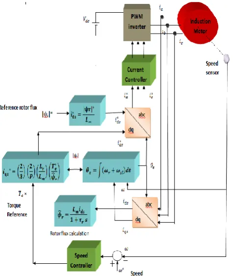
Figure 3.1: complete diagram of indirect vector control inductionmotor
The algorithm of indirect vector control is given as:
1. The induction motor is fed by a variable
frequency, variable voltage PWM inverter, which operates in current control mode. The motor speed ω is compared with the reference speed ω* and the error is produced which is fed to the speed controller. The output of speed controller is electromagnetic torque Te*.
2. The quadrature-axis stator current reference iqs* is calculated from electromagnetic torque reference Te* as
( ) ( ) ( ) (
̂)
Where ̂ |ψr|est is the estimated value of rotor
flux linkage given by
̂
Where, τr =
is the rotor time constant.
3. The direct-axis stator current reference ids* is obtained from reference rotor flux input |ψr|*.
4. The rotor flux position e required for
coordinates transformation is obtained from the rotor speed ωr and slip frequency ωsl. e is
calculated as
∫ ∫( )
5. The slip frequency is calculated from the stator reference current iqs* and the motor
parameters. is given by from eqn 4.31,
6. The iqs* and ids* current references are
converted into phase current references ia*, ib*,
ic* using inverse park transform (two phase to
three phase conversion) & fed to the current
controller. The controller processes the
measured and reference currents to produce the inverter gating signals.
The main role of the speed controller is to keep the motor speed equal to the speed reference input in steady state and to provide a good dynamic response during transients & the closed loop current control operates the voltage source inverter in current control mode which ensures that the winding current follow same pattern as that reference currents generated from control logic.
IV. SIMULATION RESULTS &DISCUSSION
This section summarise the results of proposed algorithms. The indirect vector control induction motor models tested in MATLAB/Simulink & result of proposed models are discussed in this section
4.1: Simulation Result of Induction Motor Using Open Loop Model
International Journal of Emerging Technology and Advanced Engineering
Website: www.ijetae.com (ISSN 2250-2459,ISO 9001:2008 Certified Journal, Volume 3, Issue 10, October 2013)
[image:4.595.49.291.134.404.2]719
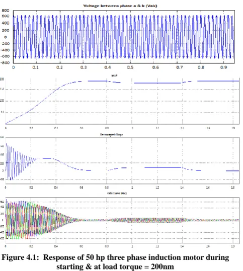
Figure 4.1: Response of 50 hp three phase induction motor duringstarting & at load torque = 200nm
4.2: Indirect Vector Control Simulation Result
The results shown below were obtained using different speed controller from figure.4.2 to 4.4, for stator voltage, stator current, rotor speed & electromagnetic torque.
(a) PI controller
[image:4.595.314.569.134.400.2](b) PID controller
Figure 4.2: Starting & full load (200 nm) response of Indirect vector control induction motor drive (IVCIMD) with
(a): PI controller & (b): PID controller
International Journal of Emerging Technology and Advanced Engineering
Website: www.ijetae.com (ISSN 2250-2459,ISO 9001:2008 Certified Journal, Volume 3, Issue 10, October 2013)
[image:5.595.314.564.134.418.2]720
(b) PID controllerFigure 4.3: Performance of IVCIMD during speed reversal from (+171 rad/sec) to (-171 rad/sec) with
(a): PI controller & (b): PID controller
(a) PI controller
[image:5.595.50.292.412.740.2](b) PID controller
Figure 4.4: Performance of IVCIMD during speed reversal from (-171 rad/sec ) to (+171 rad/sec) with
(a): PI controller & (b): PID controller
4.3 Matlab Code Result
[image:5.595.329.523.554.713.2]A MATLAB Code result is present below for Speed Control of 3-phase Induction motor using Variable Rotor Resistance, Variable Stator Voltage, Constant V/F Control (Scalar control) & Variation of d-axis stator current, q-axis stator current with change in voltage to observe Torque-Speed characteristics.
International Journal of Emerging Technology and Advanced Engineering
Website: www.ijetae.com (ISSN 2250-2459,ISO 9001:2008 Certified Journal, Volume 3, Issue 10, October 2013)
[image:6.595.55.547.102.731.2]721
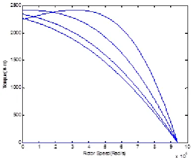
Figure 4.6: Torque vs Rotor Speed for variable Stator VoltageFigure 4.7: Torque Vs Rotor Speed for using Constant V/f
contro
(a) q-axis
[image:6.595.317.530.107.314.2](b) d-axis
Figure 4.8: Variations in q-axis & d-axis stator currents with change in stator voltage
(a): q-axis current Vs Vrms & (b): d-axis current Vs Vrms
4.5 simulation result discussion
The performance of open loop model of induction motor & indirect vector control induction motor drive (IVCIMD) has been simulated in MATLAB environment using simulink & simpower toolboxes .A comparative study has been made based on different operating condition such as starting, loading, speed reversal. A MATLAB code result for different speed control method of induction motor is also present & compare with the simulation results of IVCIMD.
[image:6.595.64.259.145.307.2]The figure 4.1 & 4.2 shows starting & full load response of open loop model & IVCIMD with PI & PID speed controller. The Table-1, given below shows the comparative results during starting.
Table 1 :Comparison of starting performance of indirect vector control induction motor drive (IVCIMD) & open loop induction
motor model
Open loop control
IVCIMD using PI controller
IVCIMD using PID controller
RMS A.C mains starting current (A)
620 452 397
Speed (rad/sec) 187.7 186.3 134.1
Starting torque (Nm) 1657 310.2 302.8 Settling time (sec) 0.71 1.23 0.85
Current drawn during loading condition (A)
81.76 94.2 88.1
The results of open loop control shows high starting current as compare to IVCIMD. The ripple content in speed waveform of open loop model during starting has been eliminated in IVCIMD.
0 1 2 3 4 5 6 7 8 9 10
x 104 0
500 1000 1500 2000 2500
To
rq
u
e
(N
-m
)
Rotor Speed(Rad/s)
0 2 4 6 8 10 12
x 104
0 100 200 300 400 500 600 700 800 900
To
rq
u
e
(N
-m
)
Rotor Speed(Rad/s) * 100
Vrms (stator current)
Id
axis c
urr
en
t
Vrms (stator current)
Iq
a
xis c
ur
re
nt
[image:6.595.310.556.520.696.2]International Journal of Emerging Technology and Advanced Engineering
Website: www.ijetae.com (ISSN 2250-2459,ISO 9001:2008 Certified Journal, Volume 3, Issue 10, October 2013)
722
The IVCIMD reaches to steady state earlier & torque settle faster as compare with open loop response. The load torque of 200 Nm is applied at 1.51 sec, so the momentary speed decreases is little less in IVCIMD with PID as compare with open loop & IVCIMD with PI controller response.
The figure 4.3 & 4.4 shows the IVCIMD response during speed reversal with PI & PID controller & its comparison is given in Table-2 shown below:
Table 2 : Comparison performance of indirect vector control induction motor drive (IVCIMD) using PI & PID controller during speed reversal IVCIMD using PI controller IVCIMD using PID controller
Reversal time (sec) 2.16 1.16
Speed during reversal (rad/sec) +186.3 to -186.3
+134.1 to -134.1
RMS A.C current drawn during reversal (A)
120 101
Electromagnetic torque during reversal (Nm)
-303 -303
Forward braking time duration (sec)
1.5 to 2.4 1.1 to 1.73
Reverse motoring time duration (sec)
2.4 to 3.6 1.73 to 2.23
The overall performance of IVCIMD is improved with PID controller & speed response also reaches the reference values earlier with PID as compare to PI controller.
[image:7.595.314.550.437.759.2]The figure 4.5 shows Torque-speed characteristics of 3-phase induction motor with variable rotor resistance .With increase in value of rotor resistance from 0.228 ohm to 0.9 ohm results shows increase in stating torque value with reduce in starting current. After maximum torque, the value of torque decrease with increase in rotor resistance. Such method is highly in sufficient. The figure 4.6 shows Torque-speed characteristics for variable supply voltage from 200v to 460 v. The developed torque varies square of the supply voltage so, increase in supply voltage result in increase in electromagnetic torque. However it will occur at same slip. Even the starting & over all torque is reduced. The figure 4.7 shows constant v/f characteristics. By varying the voltage & frequency by same ratio, flux & hence the torque can be kept constant through the speed range.
The last characteristic in figure 4.8 shows
characteristic between d-axis & q-axis current versus stator voltage, as stator voltage increase with simultaneously increase in q-axis current & decrease in d-axis current.
V. CONCLUSION
In this paper different speed control method of three phase induction motor has been made under various operating condition such as starting, speed reversal, load perturbation. From the result of implementation , carried out in MATLAB ,it has been found that indirect vector control drive with PID controller has better response as compare with PI controller. It obtained reduced starting current, less ripple content in torque waveform & settle faster. The open loop results contain high ripple during starting of speed response. The indirect vector control drive reaches earlier to steady state as compare with other result of Matlab code. So, the overall performance of indirect vector control induction motor drive is better & gives quick torque response near zero speed. It control both phase as well as magnitude & fulfil the requirement of wide speed control range & individual torque control
Acknowledgement
The authors would like to express their sincerest gratitude to the Dr.Shailendra Sharma, SGITS indore & Prof.Rahul Agrawal, Head of Department,VITs indore for providing all the possible better facilities to carry out the research work.
REFRENCES
[1] Mohan, Undeland, Robbins.Wiley ,“Power Electronic”, second edition.1989.
[2] N.P Quang, J.A. Dittrich,“Vector control of 3 phase ACmachines ,Springer, 2008.
[3] Bruno Francois, Philippe Degobert,“Vector control of induction machines” Springer February 9, 2012
[4] Ali S.Ba-thuya,Rahul Khopkar, Kexin Wei Hamid,A.Toliyat, “Single phase induction motor drives- A Literature survey”,Electric Machines & Power Electronics Laboratory Texas [5] R.Krishnan ,“Electric motor drives-modelling, analysis &
control”, 2001 Prentice Hall
[6] F.Blaschke,“The principle of field orientation as applied to new transvector close loop system for rotating field machine”,1972 [7] P.Vas,“The control of A.C machine” Oxford Univ. 1990. [8] Krause P. C,“Analysis of Electric Machinery” Mc Grow-Hill,
New York, 1986
[9] B.K.Bose,“Modern Power Electronics and AC Drives”, Pearson Education, 4th Edition, 2004
[10] Aung Zaw Latt, Ni Niwin ,“Variable speed drives of single phase induction motor use in frequency control methods”,International conference on education technology & computer,2009.
[11] S Jeevananthan,“Matlab / Simulink - A Tool for Power Electronic Circuits”, Pondicherry Engineering College Pondicherry [12] KrauseP.C, C.S.Thomas “Simulation of symmetrical induction
machinery”, IEEE Trans. on Power Apparatus & Systems, vol. 84, no. 11, 1965, pp. 1038- 1053.
[13] M.P.Kazmierkowaski,L.Malesani, “PWM Current Control Techniques of voltage source converters-A Survey”,IEEE. Trans. On Industrial Electronics, Oct.1998.Vol.45.
International Journal of Emerging Technology and Advanced Engineering
Website: www.ijetae.com (ISSN 2250-2459,ISO 9001:2008 Certified Journal, Volume 3, Issue 10, October 2013)
723
[15] Dal Y. Ohm Drivetech, “Dynamic Model Of Induction Motors For Vector Control”, Inc., Blacksburg, Virginia.
[16] Z.V.Lakaparampil,V.T. Ranganathan, “Modelling, Simulation & Implementation of vector controlled Induction Motor Drive” [17] Alexandru Onea, Vasile Horga, Marcel Ratoi,“Indirect Vector
Control of Induction Motor”,Department of Electric Drives "Gh. Asachi", Technical University of Iaşi Bd. Mangeron. 53A, 6600, Iaşi, Romania.
[18] C.M.Ong, “Dynamic Simulation of Electric Machinery”, PrenticeHall,New Jersey,1998
[19] R.H Park,“Two-Reaction Theory Of Synchronous Machine-Generalized Method Of Analysis Part 1”, AIEE Trans,vol 48 ,pp.716-727 July 1929.
[20] Dheeraj Joshi, Meghna Gill,“Comparison Of Vector Control Techniques For Induction Motor Drives”, Indian Journal Of Electrical Biomedical Eng., Vol 1.2013
[21] Bhim ,B.N & B.P Singh,“Performance Analysis Of A Low Cost Vector Control Induction Motor Drive”, IEEE IAS Conf, pp 789-794,1997
[22] Mohammad Zadeh Rostami, “Analysis Of Indirect Rotor Field Oriented Vector Control Of Squirrel Cage Induction Motor Drives”, IEEE International Conf.6-7 June 2012
[23] Selmon,G.R ,“Modeling Of Induction Machine For Electric Drives”, IEEE Vol 25,Issue 6,1989
[24] A.Khodabakshian, K Jamshidi,“Vector Control Of Induction Motor Using Upwm Voltage Source Inverter”, G.Esmeily, Isfahan Unv.,Iran
[25] Luigi Malesani & Paolo Tomasin,“PWM Current Control Technique Of Voltage Source Converter”,Univ Of Podova,Italy [26] C.S Sharma,Tali Nagwani, “Simulation & Analysis Of Pwm
Inverter Fed Induction Motor Drives”, Ijsetr Vol 2,Feb 2013 [27] G,Kohlrursz,D.Fodar,Hungavan, “Comparision Of Scalar &
Vector Control Strategies Of Induction Motor”, Journal Of Industrial Chemistry Veszprem,Vol 39 ,2011
[28] S.Corino,E.Romero,“How The Efficiency Of Induction Motor Is
Measured”, L.F Mantilla, IEEE
[29] Ashutosh Mishra, Prashant Choudhary, “Speed Control Of An Induction Motor By Using Indirect Vector Control Method” IJETAE, dec 2012
[30] Hasse K “On the dynamic behavior of induction machines driven by variable frequency and voltage sources” , ETZ Arch. Bd. 89, H. 4, 1968, pp. 77-81.
[31] Atkinson D. J., P. P. Acarnley and J. W. Finch, “Application of estimation technique in vector controlled induction motor drives”, IEEE Conference Proceeding, London, July 1990, pp. 358-363. [32] Chan C. C., Leung W. S. and C. W. Nag,“Adaptive decoupling
control of induction motor drives,” IEEE Transaction on Industrial Electronics, vol. 35, no. 1, Feb. 1990, pp.41-47. [33] I.Takahashi & T.noguchi “A new quick response & high
efficiency control strategy of induction motor”,IEEE Trans.Ind,1986.
[34] Gilbert Sybille, Patrice Brunelle,“Simpower System-User Guide”, Trans Energie Technology, 2001
[35] Santosh B. Kulkarni, Rajan H. Chile,“MATLAB/SIMULINK Simulation Tool for Power Systems”, IJPSOE 2011
[36] G.K.Dubey,“Fundamental Of Electrical Drives”, Narosa Publication, Second Edition, 2011
[37] Atul M. Gajare, Nitin R. Bhasme,“A Review on Speed Control Techniques of Single Phase Induction Motor”,IJCTEE Vol 2, Issue 5, October 2012
[38] Mohamayee Mohapatra, B.Chitti Babu,“Fixed and Sinusoidal-Band Hysteresis Current Controller for PWM Voltage Source Inverter with LC Filter”, Member IEEE,2010
[39] Novotny, D.W., Lipo,"Vector Control and Dynamics of AC Drives",T.A. 1996 Oxford University Press, New York
[40] Correa, M.B.R,"Field Oriented Control of a Single-Phase Induction Motor Drive", Conf. Rec. Power Electronics Specialists, PESC'98, Fukuoka, Japan, Vol. II, pp. 990-996,1998.
[41] G.J. Ritter, Budape, Kelemen, A., Imecs.M,"Vector Control of AC Drives", 1987.
[42] Texas Instrument, “Field Orientated Control of 3-Phase AC-Motors”
[43] S.Albert Alexander,“A Comparison of Simulation Tools for Power Electronics”,ISCI 2012
[44] Abbondanti, Brennen, M.B,“Variable speed induction motor drives use electronic slip calculator based on motor voltages and currents”, IEEE Trans.on Indus. Applications. IA-11 pp. 483– 488,1975.
[45] K. Koga, R. Ueda, T. Sonoda,“Achievement of high performances for general purpose inverter drive induction motor system”, IEEE IAS Annual Meeting, pp. 415-425, conf.1989.
[46] A. Munoz-Garcia, T.A. Lipo ,D.W. Novotny, “A new induction motor open-loop speed control capable of low frequency operation”, IEEE Trans. on Industry Applications, vol. 34, July/August, pp. 813-821.
[47] T. Sukegawa, K. Kamiyama, T. Matsui, T. Okuyama, “Fully digital, vector controlled PWM-VSI fed AC drives with an inverter dead-time compensation strategy”.IEEE IAS Annual Mtg., pp. 463-469,1988.
[48] D.W. Novotny , T.A. Lipo,“Vector control and dynamics of AC drives”,Oxford Press, Oxford England,1996.
[49] R.de Doncker, D.W. Novotny, “The universal field oriented control- ler”,IEEE IAS Annual Meeting, p. 450-456 Oct.1988. [50] X. Xu, D.W. Novotny, “Selection of the flux reference for
induction machines in the field weakening region”, IEEE vol.28, pp. 1353-1358 November/December 1992.
[51] K.B. Nordin, D.W. Novotny and D.S. Zinger, “The influence of motor parameter deviations in feedforward field orientation drives systems”, IEEE Trans. in Industry Applic., vol. IA-21, no. 4, pp. 1009-1015, July/August 1985.
[52] Q. Yao,D.G. Holmes, “A simple, novel method for variable-hystere- sis-band current control of a three phase inverter with constant switching frequency”,IEEE IAS Annual Meeting, , pp. 1122- 1129,1993.
[53] A.Ansari, D.M. Deshpande, “Mathematical Model of Asynchronous Machine in MATLAB Simulink”, International Journal of Engineering Science and Technology Vol. 2(5), , pp.1260-1267, 2010
[54] R. Lee, P. Pillay ,R. Harley, "D,Q reference frames for the simulation of induction motors," FPSR Journal, vo1.8. October [55] K. H. Bayer, H. Waldmann, M. Weibelzahl, "Field-Oriented
Closed-Loop Control of a Synchronous Machine with the New Transvector Control System," Siemens vol. 39, pp. 220- 223, 1972.
[56] Kelemen, A. G.J. Ritter, Budapest,"Vector Control of AC Drives", Imecs, M. 1987.
[57] Kovacs, P.K.,"Transient Phenomena in Electrical Machines", Elsevier Science Publihsers, Amsterdam1984.
[58] Kovacs, P.K., Racz, L. 1959. "Transiente Vorgänge in Wechselstrommaschinen", Ungarischen Akademie der Wissenschaften, Budapest
[59] Lai, Y-S. 1999. "Modelling and Vector Control of Induction Machines- a New Unified Approach", in Conf. Rec. Power Engineering Soc. Winter Meeting, Vol. I, pp. 47-52
International Journal of Emerging Technology and Advanced Engineering
Website: www.ijetae.com (ISSN 2250-2459,ISO 9001:2008 Certified Journal, Volume 3, Issue 10, October 2013)
724
[61] Popescu, M., Navrapescu, V. 2000. "Modelling in Stationary Frame of Single and Two-phase Induction Machines Including the Effect of Iron Loss and Magnetising Flux Saturation" - in Proceedings of International Conference of Electrical Machines, ICEM 2000, 28-30 August, Espoo, Finland, Vol. I, pp. 407-411 [62] Popescu,"Analysis and Modelling of Single-phase Induction
Motor with External Rotor for Domestic Applications" - in Proceedings of IEEE-IAS Annual Meeting, 8-12 October, Rome, Italy, Vol. I, pp. 463-470.
[63] Slemon, G.R. "Electrical Machines for Variable-Frequency", in Proceedings of the IEEE, Vol. 82, No. 8, pp.1123-1138,1994. [64] R.W.Smeaton, “Motor Application and Maintenance” Handbook,
McGraw Hill Book Co.
[65] W.I.Ibrahim,.M.T.Raja,Ismail,M.R.Ghaz ali, “Development of Variable Speed Drive for Single Phase Induction Motor Based on Frequency Control”, 4th Engineering Conference (EnCon 2011), 29 Nov - 1 Dec 2011.
[66] D.S.Henderson,“Variable Speed Electric Drives – Characteristics & Applications”, Bulletin Adjustable Frequency Control (Inverters) fundamentals application Consideration, C870A. [67] A.S.Zein El-Din, A.E.El-Sabbe,” A Novel Speed Control
Technique for Single-Phase Induction Motor,” IEEE International Conference on Power Electronics and Drive Systems, PEDS'99, July 1999, Hong Kong.
[68] Wade S, Dunnigan MW, Williams BW, “Modeling and simulation of induction machine vector control with rotor resistance identification”IEEE Trans Power Electronics 1997. [69] Lin, F. K. Liaw, C. M. “Control of indirect field-oriented
induction motor drives considering the effects of dead-time and parameter variations.” IEEE Trans. Indus. Electro.Vol. 40, pp.486-495.1993.
[70] www.renesas.com [71] www.mathwork.com
AUTHOR’S PROFILE
Rakesh Singh Lodhi presently working as a Assistant Professor in Department of Electrical & Electronics Engineering at Vindhya Institute of Technology & Science, Indore (M.P.) India. He is a graduate of university of RGPV in Bhopal. He was awarded a Master’s
degree in Power Electronics from
SGSITS, Indore. Rakesh Singh Lodhi wrote 8 papers mostly in 2011s. His current research interests include power electronics, electrical machines, Control and drives.
Payal Thakur was born in Madhya Pradesh, India in 1987. She received the B.E degree in Electrical & Electronics Engineering from RGPV university, Bhopal India in 2009.She is currently working towards the M.Tech. degree in
the Department of Electrical &
Electronics Engineering at Vindhya