ABSTRACT
This paper presents a slotted multiband antenna design achieved by loading a pair of L shaped slots in a rectangular micro strip antenna (RMSA). The proposed designed antenna resonates at three frequencies namely 2.7 GHz, 3.65 GHz and 5.7 GHz. Proposed antenna designed results in an increment of 33% bandwidth with stable characteristics, such as return loss, VSWR, radiation pattern, gain and impedance matching. Antenna can be very useful for WiMAX and WLAN applications. IE3D virtual platform is used for simulation of designed antenna.
Keyword
Microstrip, L shaped slots, Bandwidth, Return Loss.
1. INTRODUCTION
Microstrip antennas have gained more attention of researchers in recent times due to their light weight, small size, easy reproduction and integratibility with the circuitry. However in their general form, these antennas are found less suitable for modern communication systems including wireless systems as they can resonate at a single frequency and exhibit narrow bandwidth and poor gain. In recent times to modify antenna structures and to improve their performance in modern communication system is the need of the wireless area. Patch antennas for dual and triple band characteristics are well studied in most of the literature having fairly wide bandwidth and high gain [1,2].
Microstrip antenna find’s its use in Wireless Local Area Network (WLAN), which uses radio waves as transmission media to provide a network connection to all users in the surrounding area. Specification used in the WLAN is the IEEE 802.11, commonly referred to as Wi-Fi (Wireless Fidelity). Currently there are four variations of the 802.11 that is 802.11a, 802.11b, 802.11g and 802.11n. IEEE 802.11, WLAN has range of frequencies, namely- 2.4 - 2474 GHz, 5.15 to 5.35 GHz, 5.475-5.725 GHz and 5.725-5.825 GHz. WiMAX is a broadband technology that has access to high speed, wide reach provides a broadband connection over long distances [3].
During past 2 decades many methods have been proposed to enhance the bandwidth of microstrip antenna such as adding an impedance matching network, using slots, using stacked patches, edge-coupled parasitic patches, fractal patch or lossy materials [4,5,6,7]. Inserting a slot on the patch antenna can reduce the resonant frequency while reducing the dimensions of the antenna. By creating appropriate slot antenna dimension can be reduced, making antenna useful for wideband and multi frequency application [8,9]. Demand of antenna that has multiband characteristic is more desirable
In this paper a new designed is proposed for a conventional microstrip patch antenna loaded with three pair of L-shaped slots for triple-band operation. The proposed antenna is simulated using virtual platform IE3D [12]. This paper consist IV sections. Brief introduction is discussed in section 1. Section 2 describe proposed antenna design. Result analysis and performance comparison with conventional RMSA and the modify conventional RMSA loaded with one, two & three pair of L-shaped slots is discussed in section III. Section IV concludes the paper. References used in paper are presented in section 5.
2. ANTENNA DESIGN
Slotted antenna is designed on a FR4 substrate with relative permittivity of 4.4 and plane at a height of 1.59 mm. The conventional micro strip patch antenna is modifed into multiple steps to achived Proposed antenna geometry, they are as follow-
2.1 The Proposed Conventional Antenna
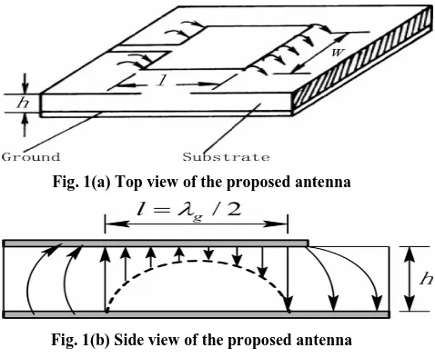
The configuration of the conventional printed micro strip patch antenna is shown in Fig. 1(a,b) with L=20mm, W=22mm, Microstrip line feed is placed at appropriate place to match with its input impedance 50 ohm.Fig. 1(a) Top view of the proposed antenna
Fig. 1(b) Side view of the proposed antenna Fig.1 Geometry of proposed conventional microstrip
patch antenna.
[image:1.595.319.558.466.663.2]Fig. 2 Variations in reflection coefficient of proposed conventional RMSA with frequency
[image:2.595.57.283.81.279.2]Fig. 3 Variations in VSWR of proposed conventional RMSA with frequency
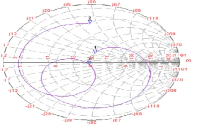
Fig. 4 Variations in input impedance of proposed conventional RMSA with frequency
The proposed conventional microstrip patch antenna has a field gain of 2.20 dBi and field directivity 6.5 dBi, as shown in Fig. 5 & 6.
Fig. 5 Variations in field gain of of proposed conventional RMSA with frequency
Fig. 6 Variations in field directivity of of proposed conventional RMSA with frequency
2.2 Modified Conventional RMSA Loaded
with One Pair of L-Shaped Slots
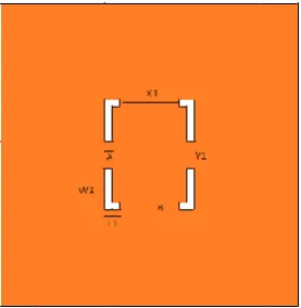
[image:2.595.361.500.301.443.2]Modified antenna consists of a one pair of L-shaped slots etched on conventional microstrip patch antenna to increase the return loss, gain and bandwidth as in Fig. 7. One pair consist four L-shaped slots as shown in below figure.
Fig. 7 Geometry of modified conventional RMSA loaded with one pair of L-shaped slots
[image:2.595.66.261.372.501.2]Simulation results of modified conventional microstrip patch antenna have reflection coefficient= -25.5 dB, VSWR= 1.11, smith chart impedance= 47.23-j3.503 at resonating frequency 3.2 GHz as shown in Fig. 8, 9 & 10 respectively.
Fig. 8 Variations in reflection coefficient of modified conventional RMSA loaded with one pair of L-shaped
[image:2.595.321.560.527.663.2] [image:2.595.65.286.573.693.2]Fig. 9 Variation in VSWR of modified conventional RMSA loaded with one pair of L-shaped slots with
[image:3.595.321.564.76.219.2]frequency
Fig. 10 Variations in input impedance modified conventional RMSA loaded with one pair of L-shaped
slots with frequency
2.3 Modified Conventional RMSA Loaded
with Two Pairs of L-Shaped Slots
Modified antenna consists of a two pairs of L-shaped slot is etched on the conventional microstrip patch in Fig. 11.
Fig. 11Geometry of modified conventional RMSA loaded with two pairs of L-shaped slots
[image:3.595.319.556.78.566.2]Simulation results of modified proposed conventional microstrip patch antenna have reflection coefficient= -23 dB, VSWR= 1.2, smith chart impedance= 44.31-j0.90 at resonating freruency 3.5 GHz as shown in Fig. 12,13 & 14 respectively.
Fig. 12 Variations in reflection coefficient of modified conventional RMSA loaded with two pairs of L-shaped
slots with frequency
Fig. 13 Variation in VSWR of modified conventional RMSA loaded with two pairs of L-shaped slots with
frequency
Fig. 14 Variation in input impedance of modified conventional RMSA loaded with two pairs of L-shaped
slots with frequency
2.4 Modified Conventional RMSA Loaded
with Three Pairs of L-Shaped Slots
[image:3.595.64.261.248.376.2] [image:3.595.97.236.470.609.2]Fig. 15 Geometry of modified conventional RMSA loaded with three pairs of L-shaped slots
[image:4.595.97.235.71.202.2]Simulation results of this modified proposed conventional microstrip patch antenna have reflection coefficient=(-25dB, -27.5dB, -19dB), VSWR= (1.2, 1.2, 1.3), smith chart impedance (44.16-j2.97, 44.20+j8.63, 57.60+j10.75) with resonating frequency 2.7GHz, 3.65GHz, 5.7GHz as shown in Fig. 16, 17 & 18 respectively.
Fig. 16 Variations in reflection coefficient of modified conventional RMSA loaded with three pairs of L-shaped
slots with frequency
Fig. 17 Variation in VSWR of modify conventional RMSA loaded with three pairs of L-shaped slots with
frequency
Fig. 18 Variation in input impedance of modified conventional RMSA loaded with three pair of L-shaped
slots with frequency
[image:4.595.325.536.80.220.2]Variation in return loss, resonating freq., bandwidth & size reduction of modified designs (Step I to Step IV) are shown by Fig. 19, 20, 21 & 22.
[image:4.595.319.542.293.710.2]Fig. 19 Variation in Return loss Vs. Modified design
Fig. 20 Variation in Resonating freq. Vs Modified design
Fig. 21 Variation in Bandwidth Vs Modified design
-24.5 -25.5 -23 -25
-27.5 -19
Modified Designs Vs.
Return Loss (dB)
3.4 3.2 3.5 2.73.65
5.7
Modified Designs Vs.
Resonating Frequency …
8.00 9.37
17.14
7.4 33
14.03
Modified Designs
[image:4.595.55.292.306.439.2] [image:4.595.59.293.492.629.2]Fig. 22 Variation in Size reduction Vs Modified design
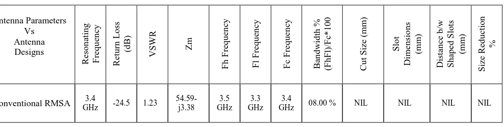
3. RESULT ANALYSIS
Result obtained for all steps of modified antenna is presented in Table 1. It can be seen that resonant frequency decreases as the number of slots increases. Fig.16 shows the variation of return loss with three resonating frequencies 25dB, -27.5dB & -19dB respectively is significant. Fig. 18 shows the input impedance loci using smith chart, input impedance curve passing near to the 1 unit impedance circle that shows the perfect matching of input. Fig. 17 shows the VSWR of the proposed antenna that is 1.2 at the resonant frequency 2.7 GHz, 1.2 at the resonant frequency 3.65 GHz and 1.3 at the resonant frequency 5.7 GHz.
4. CONCLUSIONS
Simulation results of proposed antenna design with three pair of L- shaped slots shows resonant frequencies 2.7GHz, 3.65GHz & 5.7GHz with available impedance band width 07.40%, 33.00% & 14.03% respectively. The bandwidth obtained is remarkable as far as the simplicity of the geometry is concerned and may be useful for triple band operation. It may be further concluded that antenna have reduced size, simpler and possesses better results. For future enhancement can focus on directivity, gain and other parameters of antenna.
5. REFERENCES
[1] Maci S., Gentili G.B., “Dual-frequency patch antennas”, Antennas and Propagation Magazine, IEEE, Vol.39, No.6, pp.13-20, December 1997.
[2] Kimura, “Single-Layer U-Slot Rectangular MSA for Multiband Operation”, Proc. IEEE AP-S Int. Symp., 310.8, pp.1-4, July 2008.
Appication, ISSN:0975-8887, Vol.107, No-4,pp16-19, December 2014.
[5] C. A. Balanis "Antenna Theory, Analysis and Design" JOHN WILEY & SONS, INC, New York 1997. [6] K. F. Lee, Ed., “Advances in Microstrip and Printed
Antennas” John Wiley, 1997.
[7] Kritika Mathur, O. P. Sharma “Analysis of Stacked patch Antenna with variation in couplers in ultra wideband” International Journal of latest technology in engineering, management & applied science, ISSN:2278-2540, Vol.3, Issue-9, pp105-108, November 2014.
[8] Arnab Das, Bipa Datta, Samiran Chatterjee, Moumita Mukherjee, Santosh Kumar Chowdhury, "Multi-resonant Slotted Microstrip Antenna for C, X and Ku-Band Applications", IOSR Journal of Electrical and Electronics Engineering (IOSR-JEEE), ISSN (2278-1676), Vol. 2, Issue 6, pp 47-52, September-October 2012.
[9] Y. Shinohe, M. Haneishi, and Y. Kimura, ”Radiation Properties of Multiband Planar Antennas with Multislit”, IEICE Trans. Commun. (in Japanese), Vol. J89-B, No. 9, pp. 1589-1602, September 2006.
[10]J. Y. Jan and L. C. Tseng, “Small planar monopole Antenna with a shorted parasitic inverted-L wire for Wireless communications in the 2.4, 5.2 and 5.8 GHz. bands”, IEEE Trans. Antennas and Propag., Vol. 52, No. 7, pp 1903- 1905, July 2004.
[11]Samiran Chatterjee, Joydeep Paul, Kalyanbrata Ghosh, P. P. Sarkar and S. K. Chowdhury, “A Printed Patch Antenna for Mobile Communication”, Convergence of Optics and Electronics conference, Paper ID 15, pp 102-107, 2011.
[12]IE3D Simulation Software, Zeland, version 14.05.2008.
Table1- Comparison between RMSA and different types of modified RMSA (Loaded with one, two & three pair of L-shaped slots) Antenna Parameters Vs Antenna Designs Re so n ati n g F re q u en cy Re tu rn L o ss (d B) VSW R Zm F h F re q u en cy F l F re q u en cy F c F re q u en cy Ba n d wid th % (F h F l)/ F c* 1 00 Cu t S ize (m m ) S lo t Dim en sio n s (m m ) Dista n ce b /w S h ap ed S lo ts (m m ) S ize Re d u cti o n %
Conventional RMSA GHz 3.4 -24.5 1.23 54.59-j3.38 3.5 GHz 3.3 GHz 3.4
Conventional RMSA loaded
with one pair
3.2
GHz -25.5 1.11
47.23- j3.50
3.35 GHz
3.05 GHz
3.2
GHz 9. 37 %
A=0.5 B=0.5
L1=1 W1=3
X1=4 Y1=2
1.59 %
Conventional RMSA loaded
with two pair
3.5
GHz -23.0 1.2
44.31- j0.90
3.8 GHz
3.2 GHz
3.5
GHz 17.14 %
A=0.5 B=0.5
L1=1 W1=3
L2=2 W2= 6.5
X1=4 Y1=2 X2=7 Y2=2
5.22 %
Conventional RMSA loaded with three pair
2.7
GHz -25.0 1.2
44.16- j2.97
2.8 GHz
2.6 GHz
2.7
GHz 07.40%
A=0.5 B=0.5
L1=1 W1=3
L2=2 W2= 6.5
L3=3 W3=9
X1=4 Y1=2
X2=7 Y2=2
X3=10 Y3=2
10.45 % 3.65
GHz -27.5 1.2
44.20- j8.63
4.65 GHz
3.33G Hz
3.65
GHz 33.00%
5.7
GHz -19.0 1.3
57.60+ j10.75
6.2 GHz
5.4 GHz
5.7