EDDY CURRENT DETECTION OF SUBSURFACE CRACKS IN ENGINE DISK BOLTHOLES
ABSTRACT
R. Palanisamy and D. O. Thompson Ames Laboratory, USDOE
Iowa State University Ames, IA 50011 and
G. L. Burkhardt and R. E. Beissner Southwest Research Institute San Antonio, TX 78284
The development of a reliable eddy current inspection system to detect second layer cracks in sleeved engine disk bolt holes poses serious difficulties. This paper discusses some initial results obtained in two separate investigations that are aimed at advancing the state-of-the-art in eddy current detection of subsurface cracks. Both finite element design optimization results of a horseshoe shaped ferrite core probe, and the results of
preliminary evaluation of the applicability of electric current perturbation (ECP) technique to the current problem are presented in this paper.
INTRODUCTION
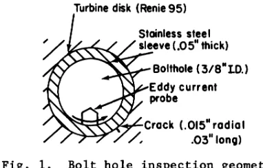
The development of a reliable eddy current inspection system to detect second layer cracks (0.03" x 0.015") in the sleeved (0.05" thick stainless steel) turbine disk boltholes poses serious difficulties. l Commercial eddy current units could not detect 0.06" x 0.03" EDM flaws (double the target size) behind 0.05" thick sleeve in a simulated bolthole specimen. It was found theoretically that the sleeve, because of higher electrical conductivity compared to that of the disk material, has significant affect on the sen-sitivity and transverse resolution of the sensor due to shielding
and current spreading. Partial and perhaps variable insulating layer between the sleeve and disk also affect the detection reli-ability.
Using a two-dimensional finite element numerical model, a theoretical sensitivity analysis was performed on various probe configurations of practical utility. From these studies, it was concluded that a horseshoe shaped ferrite core probe, due to its special magnetic characteristic (focussing concentrated field directly into the second layer), is capable of providing better sensitivity than other types. The design optimization results of this probe are presented.
The feasibility of detecting undersleeve cracks with electric current perturbation (ECP) technique was established through labor-atory evaluation. Preliminary experiments with a simulated bolthole specimen show that with the ECP method, a flaw 0.06" x 0.03" is easily detected through a 0.05" stainless steel insert. However, a smaller flaw, 0.03" x 0.015", produced a much weaker indication. Possibilities for improving small flaw detectability are discussed. FINITE ELEMENT DESIGN OF HORSESHOE CORE PROBE
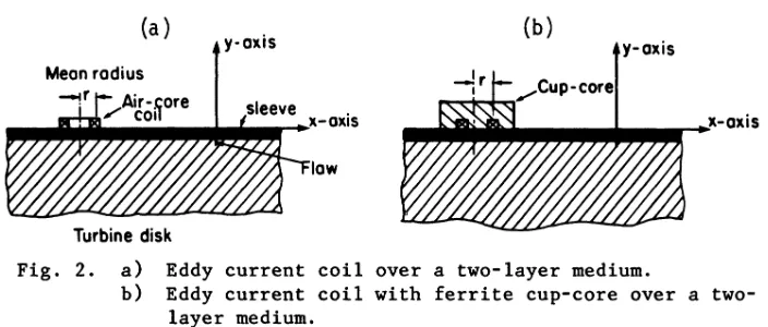
The bolthole inspection geometry (Fig. 1) and the factors that complicate the development of a reliable eddy current system to detect the second layer cracks are well described in references 1 and 2. Initially, using a two-dimensional finite element numeri-cal model, a theoretinumeri-cal sensitivity analysis was performed on an absolute eddy current coil (Fig. 2) with and without ferrite cup core (sensitivity ~I~z/zl, where ~z
=
change in impedance due to the presence of flaw, z = impedance with no flaw). The results suggested that such an eddy current system, in which the eddy currents flow in spiral path, would have to exhibit a sensi-tivity of 10-5 for the reliable detection of subsurface cracks in the present geometry.l,2 The sensitivity of commercial eddy current instruments is approximately 10-3 or less. Based uponTurbine disk (Renie 95)
Crack (,015- radial /, .036 long)
[image:2.482.133.324.500.622.2](a)
y-axis (b) y-axis
Mean radius
Turbine disk
Fig. 2. a) Eddy current coil over a two-layer medium.
b) Eddy current coil with ferrite cup-core over a two-layer medium.
these findings, it was concluded that it was highly improbable that state-of-theart eddy current instrument would be found that was suitable for this inspection.
The coil sensitivity is a measure of the degree of interaction between the field and flaw in a test specimen. Both air-core and cup-core coils produce eddy currents that flow in a spiral path in the conductor under test. For a given surface flaw, higher probe sensitivities are possible with coils whose mean radii are comparable to the crack length. Such a generalized criterion is difficult to arrive at in the case of second layer crack detec-tion, particularly when the thickness of the first layer is greater than the flaw size and the conductivity larger than that of the second layer. Therefore, one needs to use a probe that would focus a concentrated field directly into the second layer while minimizing spreading in the first layer. Theoretical results
show that a U or horseshoe shaped ferrite core probe, possessing the desired special magnetic characteristic, is capable of providing better sensitivity than air-core and cup-core probes. The results of the initial analyses are presented here.
[image:3.482.62.414.86.236.2](a)
Sleeve
Disk
Frequency
25kHz
~
{I
(/l(b)
t"J
0.0842"-,3 -.2 -.I 0 .I .2 .3
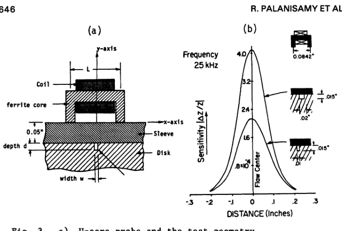
DISTANCE (Inches) Fig. 3. a) U-core probe and the test geometry
b) Finite element predicted eddy current signals for two different slots in the second layer.
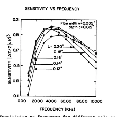
cup-core probes. This probe is not optimized to provide maximum sensitivity. which is a function of probe dimension and excitation frequency. Even then. for a specified subsurface flaw. the sensi-tivity of a U-core probe is higher than that predicted in other probes. The geometry of the U-core probe. portion of the finite element discretization. and the field plot (contours of constant magnetic vector potential amplitude) are given in Fig. 4.
The following electrical conductivity and relative magnetic permeability values were assumed for the materials involved in the numerical analyses discussed in this paper.
Material
Sleeve (stainless steel) Turbine disk (Renie 95) Probe body (ferrite)
Conductivity (ohm-m)-l 1.49 x 10⁶
0.647 x 10⁶ 1.0 x 10⁻⁶
Permeability 1.0 1.0 5000.0
[image:4.482.60.411.59.296.2](a) (b)
Fig. 4. a) Two dimensional geometry for the numerical analysis. b) Part of finite element discretization.
c) Flux plot (frequency: 40 kHz)
maximum sensitivity occurs when the probe comes directly above the flaw (i.e., for the probe position shown in Fig. 3a).
In the two dimensional analyses discussed so far it was impli-citly assumed that a) both the flaw and coil had infinite extent perpendicular to the plane of the diagrams (Figs. 2 and 3a), and b) the bolt hole diameter is infinite (i.e., the curvature effect was neglected). Within the limits of the two dimensional analysis
(assumption a) the effect of bolthole curvature on the probe sensi-tivity can be studied by considering a circular geometry instead of a flat two layer medium shown in Fig. 3a. Thus, the approximation of a sleeved bolthole geometry as a flat two dimensional media
can be eliminated altogether. It was predicted that the maximum signal amplitude coming from the circular geometry is 15.2% more than that coming from a flat two dimensional geometry.2
ELECTRIC CURRENT PERTURBATION METHOD
SENSITIVITY Vs. FREQUENCY
0.21...----r--.---....----.--:'I" Flaw width w-0.005
depth d=0.015"
rt) 0.19
'Q N
~ 0.17 <J >-~ 0.15 i=
Ui z
~O.B
1~'rI----0.16"
1-1>-___ 0.14,. /+---0.12"
O.III...-..lL--I _ _ ---L _ _ ...L _ _ ....L._~
000 20.00 40.00 60.00 80.00 100.00
FREQUENCY (KHz)
Fig. 5. Sensitivity vs frequency for different pole gaps (L in Fig. 3a).
perturbation (ECP) technique would be an appropriate candidate to evaluate for this problem. 4 This technique consists of establish-ing an electric current flow in the test specimen and then detect-ing localized perturbations of this current flow about a crack. This current perturbation is measured by using a small noncontact-ing probe to detect the associated magnetic flux perturbation as a function of position at the surface of the specimen.
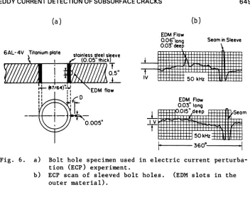
The feasibility of detecting under sleeve cracks with the ECP method was established through laboratory experiments. The drawing of a sleeved bolthole sample prepared for this experiment is given in Fig. 6a. Two boltholes were prepared and then sleeved with two flaw sizes included. One of these is the target flaw,
.030" x .015", and the other flaw was chosen to be twice these dimensions. Figure 6b shows the ECP scans of these two EDM flaws at 50 kHz. The large signal excursion on the right side of the traces is due to a seam in the insert (not visible on the exterior of the stainless steel tubing used to fabricate the sleeve). The rather appreciable base line drift seen in these charts is probably due to lift-off variations as the probe moves circumferentially around the inside of the hole. In Fig. 6b, the larger EDM slot
[image:6.482.116.358.74.321.2]649
(a) (b)
6AL-4V Titanium plate
1
0.005"
EDM Flaw
0.03"lon9
-1-llIiil·0~'51"~d~ee~p~lIlI!liSiieam
T
50kHz
11-'
---360o~--I11
Fig. 6. a) Bolt hole specimen used in electric current perturba-tion (ECP) experiment.
b) ECP scan of sleeved bolt holes. (EDM slots in the outer material).
a clear result. It would be expected on the basis of the larger flaw that the signal for this flaw would be approximately the same magnitude as the noise (which it apparently is) and therefore undiscernible with the present set-up.
[image:7.482.63.415.66.347.2]10
8
2
DIFFERENTIAL SENSOR
...-jDI-9J=(p
O~--~~~~ __ ~ __ ~~ __ ~ __ ~ ____ J
0.0 0.2 0.4 0.6 0.8 1.0 1.2 COIL SPACING D (m.m.)
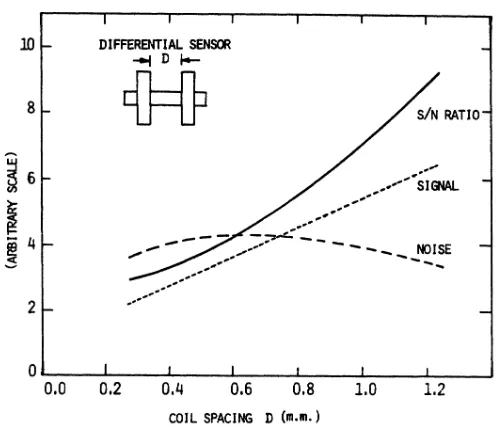
Fig. 7. Results of sensor optimization study for under sleeve crack detection uSin'g ECP technique.
CONCLUSION
From the results of the analyses it was concluded that an optimized (probe dimension and excitation frequency) U-core probe is better suited for inspecting second layer cracks compared to air-core and cup-core probes. It is recognized that the two dimen-sional modeling techniques do not accurately represent the entire problem of interest and that the results must be interpre~ed with
some caution. In a separate investigation it was shown that the 2-D calculations over estimate the sensitivity by a factor of 10 for the practical problem at hand. 5 Therefore, the theoretical results suggest that a sensitivity of /Az/z/ ~ 10-5 would be required in the instrumentation for the reliable detection of subsurface cracks in the present geometry.
The preliminary results of the ECP experiments (using surface probe), and signal/noise ratio prediction for subsurface probes are highly promising for this application. Additional work that is required to quantify the potential of state-of-art ECP probes includes estimating the magnetic flux leakage at the position
[image:8.482.99.347.84.299.2]are underway towards developing these two improved eddy current systems that would provide the required sensitivity for the sleeved bolthole inspection.
ACI<NOWLEDGEMENT
This work was sponsored by the Center for Advanced Nondestruc-tive Evaluation, operated by the Ames Laboratory, USDOE, for the Naval Sea Systems Command and the Defense Advanced Research Projects Agency under Contract No. W-7405-ENG-82 with Iowa State University. REFERENCES
1. R. Palanisamy and K. M. Lakin, "Development of an eddy current inspection technique for sleeved engine disk bolt holes", Review of Progress in Quantitative NDE, D. O. Thompson and D. E. Chimenti, Eds. (Plenum Press, NY, Vol. lA, 1983), pp. 205-223.
2. R. Palanisamy and K. M. Lakin, "Eddy current detection of subsurface cracks in sleeved bolt holes", presented at the Qualtest-II Conference, Dallas, TX, Oct. 25-27, 1983. 3. R. Palanisamy and W. Lord, "Prediction of eddy current probe
signal trajectories", IEEE Transaction on Magnetics, Vol. MAG-16, No.5, September 1980, pp. 1083-1085.
4. R. E. Beissner, C. M. Teller, G. L. Burkhardt, R. T. Smith and J. R. Barton, "Detection and analysis of electric current perturbation caused by defects", Eddy-Current Characterization of Materials and Structures, Edited by George Birnbaum and George Free, ASTM Publication Code Number (PCN) 04-722000-22, 1981, pp.428-446.
5. R. Palanisamy, R. B. Thompson and D. O. Thompson, "Estimates of eddy current response to subsurface cracks from 2-D finite element code predictions", presented at the Review of Progress in Quantitative NDE, University of California, Santa Cruz, CA, August 7-12, 1983.
DISCUSSION
From the Floor: It seems like you're modeling one type of probe and you're experimentally using another type. Can you tell me why?