UNIVERSITI TEKNIKAL MALAYSIA MELAKA
WATER BILL SYSTEM TECHNOLOGY
This report is submitted in accordance with requirement of Universiti Teknikal Malaysia Melaka (UTeM) for the Bachelor’s Degree in Computer Engineering
Technology (Computer Systems) with Honours
by
ABDUL QAYYUM BIN ABDUL HALIM B071310665
940527-10-6283
UNIVERSITI TEKNIKAL MALAYSIA MELAKA
BORANG PENGESAHAN STATUS LAPORAN PROJEK SARJANA MUDA
TAJUK: WATER BILL SYSTEM TECHNOLOGY
SESI PENGAJIAN: 2016/2017 Semester 1
Saya ABDUL QAYYUM BIN ABDUL HALIM
mengaku membenarkan Laporan PSM ini disimpan di Perpustakaan Universiti Teknikal Malaysia Melaka (UTeM) dengan syarat-syarat kegunaan seperti berikut:
1. Laporan PSM adalah hak milik Universiti Teknikal Malaysia Melaka dan penulis. 2. Perpustakaan Universiti Teknikal Malaysia Melaka dibenarkan membuat salinan
untuk tujuan pengajian sahaja dengan izin penulis.
3. Perpustakaan dibenarkan membuat salinan laporan PSM ini sebagai bahan pertukaran antara institusi pengajian tinggi.
4. **Sila tandakan ( )
SULIT
TERHAD
TIDAK TERHAD
(
(Mengandungi maklumat TERHAD yang telah ditentukan oleh organisasi/badan di mana penyelidikan dijalankan)
(Mengandungi maklumat yang berdarjah keselamatan atau kepentingan Malaysia sebagaimana yang
termaktub dalam AKTA RAHSIA RASMI 1972)
Disahkan oleh:
) ( )
Alamat Tetap:
14, JALAN KEBUN NENAS 4K/KS8,
BANDAR PUTERA 2,
41200 KLANG, SELANGOR
Tarikh: ____________________
Cop Rasmi:
Tarikh: ____________________
iii
DECLARATION
I hereby, declare that this thesis entitled “Water Bill System Technology” is the result of my own research except as cited in references.
Signature : ………
Name : ABDUL QAYYUM BIN ABDUL HALIM
iv
APPROVAL
This report is submitted to the Faculty of Engineering Technology of UTeM as one of the requirements for the award of Bachelor’s Degree in Computer Engineering Technology (Computer System) with Honours. The following are the members of supervisory committee:
v
ABSTRACT
vi
ABSTRAK
vii
DEDICATIONS
Alhamdulillah, praise to the Almighty Allah S.W.T This thesis is dedicated to :
My beloved parents, En. Abdul Halim Bin Abdul Wahab and Pn. Norhashimah Binti Shaari for raising me become who I am today. Also to my family who supported me physical, emotional, and financial support throughout the
viii
ACKNOWLEDGEMENT
First and foremost, I would like to express my deepest gratitude to Mr. Hasrul ‘Nisham Bin Rosly for giving me an opportunity working under her supervision throughout this project. Not forgetting the staffs of Faculty of Engineering Technology; my academic advisor, Madam Haryanti.
I’m also thank to En Ahmad Fairuz for his professional advices in programming the system, lab engineers for their assistance during my laboratory sessions, and also the other staffs who had been helping me indirectly.
ix
TABLE OF CONTENTS
DECLARATION……… iii
APPROVAL….……….. iv
ABSTRACT……… v
ABSTRAK... vi
DEDICATIONS……….. vii
AKNOWLEDGMENTS………. viii
TABLE OF CONTENTS ... ix
LIST OF FIGURES ... xiii
LIST OF TABLE ... xiv
LIST OF GRAPH xiv LIST OF SYMBOLS AND ABBREVIATIONS ... xv
CHAPTER 1 ... 1
1.0 Introduction ……… 1
1.1 Background ... 1
1.2 Problem Statement ... 2
1.3 Objective ... 2
1.4 Project Scope and Limitations ... 2
1.5 Project Significance ………. 3
1.6 Thesis Structure ... 3
x
CHAPTER 2 ... 5
2.0 Introduction………. 5
2.1 Past Related Researches ... 5
2.1.1 Findings by others and similar projects ……….. 5
2.2 Water Bill System Technology ………... 7
2.2.1 Advantages and disadvantages ... 8
2.3 Arduino ………... 9
2.4 Comparison between Arduino, Microcontroller and Microprocessor... 10
2.5 Arduino MEGA Board ... 11
2.6 ESP8266 Wi-Fi Module…….. ... 15
2.7 Arduino Integrated Development Environment (IDE) Software ... 17
2.8 Water Flow Sensor... 17
2.9 LCD Screen ... 19
2.10 Summary ... 19
CHAPTER 3 ... 20
3.0 Introduction……... 20
3.1 Project Planning ... 20
3.2 Flowchart ………... 21
3.2.1 Project Research ………... 25
3.2.2 Arduino Programming ……... 25
3.3 The Architecture of System ... 25
xi
3.4.1 Installing Arduino IDE Software ……….. 27
3.5 Hardware Design ………. 29
3.5.1 Block Diagram : Arduino MEGA Microcontroller………... 30
3.5.2 Block Diagram : Water Flow Sensor ……… 30
3.5.3 Block Diagram : WiFi Module (ESP8266) ……..………. 31
3.5.4 3.5.4 Block Diagram : LCD Screen ……… 31
3.6 Summary ……….. 32
CHAPTER 4 ………. 33
4.0 Introduction………... 33
4.1 Hardware………... 33
4.1.1 Water Flow Sensor……….. 33
4.1.2 ESP8266 Wi-Fi Module……….. 36
4.2 Software……… 40
4.2.1 Arduino IDE……… 40
4.2.2 Notepad++………... 41
4.3 Building Interface Design……… 41
4.4 Project Prototype……….. 42
4.5 Project Analysis ………... 43
4.5.1 The graph of Litre vs. Bill ……….. 43
4.5.2 The graph of Time vs. Bill for 1 litre (open the container cap) ………. 44
4.5.3 The graph of Time vs. Bill for 1 litre (close the container cap) ………. 45
xii
4.7 Summary……….. 46
CHAPTER 5 ………. 47
5.0 Introduction……….. 47
5.1 Conclusion……… 47
5.2 Future Works……… 49
5.3 Project Potential ……….. 50
REFERENCES ……… 51
APPENDIX A ………. 52
APPENDIX B ……….… 61
xiii
LIST OF FIGURES
Figure 2.1 : Block Diagram of Water Bill System Technology ………..8
Figure 2.2 : Arduino MEGA board ………9
Figure 2.3 : Arduino MEGA Board Front View ………11
Figure 2.4 : Arduino MEGA Board Back View ………12
Figure 2.5 : The anatomy of standard Arduino MEGA microcontroller board …...12
Figure 2.6 : ESP8266 Front View ………...……….16
Figure 2.7 : ESP8266 Back View ………...………...16
Figure 2.8 : Water Flow Sensor ………17
Figure 2.9 : LCD Screen ………19
Figure 3.1 : Flowchart of Water Bill System Technology……….21
Figure 3.2 : SDLC Phases ………22
Figure 3.3 : Flowchart of Water Bill System Technology ………24
Figure 3.4 : The Project Architecture ………26
Figure 3.5 : Connection of Arduino MEGA board with PC using USB cable …….27
Figure 3.6 : Done uploading ………28
Figure 3.7 : Coding for LED testing ……….28
Figure 3.8 : Project Block Diagram ………29
Figure 3.9 : Arduino MEGA Microcontroller………...30
Figure 3.10 : Water Flow Sensor ……….30
Figure 3.11 : WiFi Module (ESP8266) ………...31
Figure 3.14 : LCD Screen ………..………...….31
Figure 4.1 : Water flow sensor………...………...…..34
Figure 4.2 : Coding to measure the volume of water and its bill ...………...34
Figure 4.3 : Result of collected data ………..36
Figure 4.4 : ESP8266 …...………..37
Figure 4.5 : Show the ESP8266 cannot connect with Wi-Fi………...37
Figure 4.6 : show the ESP8266 connected with Wi-Fi………38
Figure 4.7 : Coding to connect with Wi-Fi ...………...38
Figure 4.8 : Coding to send the data to database……….…39
xiv
Figure 4.10 : Notepad++ interface……….42
Figure 4.11 : webpage interface……….42
Figure 4.12 : Prototype of Water Bill System Technology………43
LIST OF TABLE
Table 2.1 : Summary of Arduino MEGA Board ………12Table 2.2 : The function of each power pins on the Arduino MEGA ………...14
Table 2.3 : The function of each pin on the Arduino MEGA……….14
Table 2.4 : The specification of water flow sensor ………...17
Table 3.1 : Description Phase of SDLC based on phase in Figure 3.2 ……….22
Table 4.1 : Table of Litres and Bill ………...…………....44
Table 4.2 : Table of Time and Bill ………45
Table 4.3 : Table of Time and Bill ………..………..46
LIST OF GRAPH
Graph 4.1 : Graph of Litres vs. Bill ………..44Graph 4.2 : graph of Time vs. Bill for 1 litre (open the container cap) ………45
xv
LIST OF SYMBOLS AND ABBREVIATIONS
SMS Short Message Service IPv6 Internet Protocol version 6
AMRCS Automatic Meter Reading and Control System AMI Advanced Metering Infrastructure
ICT Information and Communications Technology PC Personal Computer
WiFi Wireless Fidelity
IDE Integrated Development Environment PWM Pulse Width Modulation
USB Universal Serial Bus
ICSP In-Circuit Serial Programming AC Alternating Current
DC Direct Current
PCB Printed Circuit Board IC Integrated Circuit CPU Central Processing Unit RAM Random Access Memory ROM Read Only Memory
ISP In-System-Programming I/O Input/Output
SRAM Static Random Access Memory
EEPROM Electrically Erasable Programmable Read Only Memory Vin Voltage Input
RX Receiver TX Transmitter
TTL Transistor-Transistor Logic LED Light Emitting Diode
xvi AREF Analog Reference
WEP Wireless Encryption Protocol WPA2 WiFi Protected Access
OS Operating System LCD Liquid-Crystal Display
SDLC Software Development Life Cycle HTML Hypertext Markup Language WLAN Wireless Local Area Network
1
CHAPTER 1
INTRODUCTION
1.0 Introduction
This chapter introduces the project with its background, problem statement, objectives, scope and project significance, to provide a sense of purpose and reasons to proceed with this project.
1.1 Background
2
1.2 Problem Statement
Many companies or house owner around the world having their own problems. The problem that faced by some companies is over budget due to their utilities bill such as water bill. Other than that, the over usage of water also is the problem that faced by users. Nowadays, the reading of water bill is in monthly. So, user doesn’t know the reading of water by day. The solution of this problem is monitor the usage of water everyday using computer via wireless connection and calculate the bill per day. The water bill system technology is designed to counter the problem that all users are facing.
1.3 Objective
The main objective of this project is deeply concentrated on aspect as listed below: i. To display the water usage based on daily used.
ii. To develop a system that calculate the water bill every day. iii. To study how Arduino control the other component.
1.4 Project Scope and Limitations
3 Arduino MEGA function well. A good programming will allow the modules to send information to each other with minimum delay. The functionality of the water bill system technology will be tested by making a simple model in which the model can make the water flow out in order to facilitate water flow sensor to calculate the total volume of water that comes out. Besides, a simple database will be create to collect the data from the Arduino and make user to monitor it using webpage. The possible flaws of the system will also be verified at the time and improvements will be made if possible.
1.5 Project Significance
Living in the globalisation era, most of the people are facing the problem to make the budget of water bill. This is because the over budget of water bill and usage of water. Many companies or house using water as main source for daily activities. At the company, the usage of water is due to the usage of employees or in the course of the work process. While at home, the usage of water is due to the daily activities such as take a bath, cook, washing the clothes, and many more. The water bill system technology will be able to help users to control this problem. With the opportunity that similar, the water bill systems technology are not common in Malaysia, this project will create awareness to the users of its feasibility and advantages it may provide in the future.
1.6 Thesis Structure
Chapter 1:
4 Chapter 2:
In this chapter, projects background is discussed. The characteristic and specifications of the component that needed is stated in this chapter. Also, the software that related with this project will be discussed. In addition, the related research also will be discussed in this chapter.
Chapter 3:
This chapter will explained about the procedure and process flow of the project.
Chapter 4:
This chapter will discuss about the data collection and analysis data obtained from the project. It is also will discuss about the problems that had to face during design the project and how to overcome it.
Chapter 5:
This chapter will discuss about the summarization of the project.
1.7 Summary
5
CHAPTER 2
LITERATURE REVIEW
2.0 Introduction
In a nutshell, the water bill system technology use Arduino and some others hardware that will help the system to perform better. The purpose of this project is to eliminate the problem that all users are facing; the over budget of water bill and usage of water in monthly.
2.1 Past Related Researches
There are numerous researches on the water bill system in the past. Listed below is part of the past related researches.
2.1.1 Findings by others and similar projects
6 hence no errors as it avoids human intervention. The billing information is sent through SMS which is a reliable and secured communication technique and also helpful for the user as the user gets the bill on time.
Due to the large number of consumers, it is not viable to collect data manually using traditional approach and analyze them on a day to day basis as it will be time consuming and data collected may be inaccurate (Palanichamy, C.; Babu, N.S.; Chelvan, R.K.; Nadarajan, C, 1999). Thus an automatic system that can measure the consumption, notify of any irregularities and is capable of providing real time data is required. With the substantial amount of advancement in technology, it is now possible to measure and acquire the consumption data and analyze them. Smart meters are the monitoring tools for energy, water and gas consumptions and are designed for recording and displaying real time usage data with the goal of reducing the energy consumption and costs. A smart meter facilitates real-time communication between the customer and the utility company offering various advantages to both the suppliers and the consumers.
7 The authors in (Carroll, J.; Lyons, S.; Denny, E., 2013) conducted a research in smart metering and their finding are that feedback significantly increases a household’s knowledge but improvements are not correlated with observed demand reductions. The data used was from a randomized controlled smart metering trial in Ireland, which also collected extensive information on household attitudes towards the knowledge of electricity use. In article (Ahmad, S., 2011), the use of the smart metering and home automation technologies for efficient utilization of energy, thus paving the way for a cleaner and greener environment for future generations have been presented. The authors have stated that tremendous work is going on in Advanced Metering Infrastructure (AMI), Smart Metering and Home Automation. Countries like USA, Australia and Italy etc. have already started using AMI solutions while countries like China, South Korea, Austria, Spain, Sweden, Finland, Denmark, Netherlands, Norway, Ireland and UK are in process of implementing AMI. Smart metering and ICT solutions have been planned to increase efficiency, loss reduction, reduce energy theft and for efficient data collection for better energy accounting in the electrical sector.
2.2 Water Bill System Technology
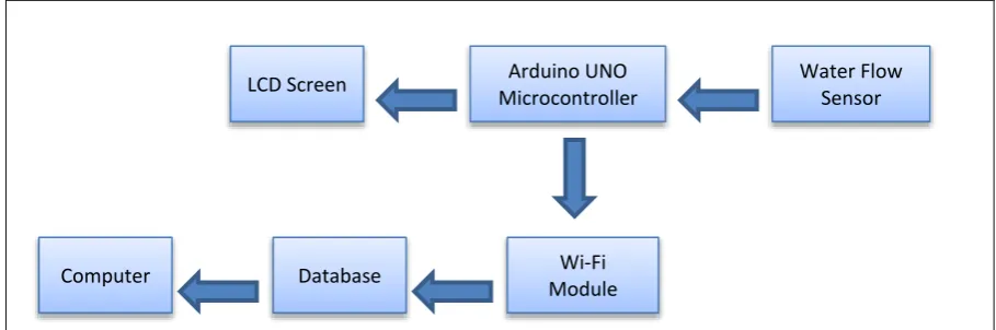
8
[image:24.595.113.568.71.222.2]
Figure 2.1 : Block Diagram of Water Bill System Technology
2.2.1 Advantage and Disadvantages
The advantages of water bill system technology is it will give an ease to the user. Since it can calculate the water bill per day, the user can spend a budget for a month to pay the water bill. After that, user can know the water usage and its bill by day. So, based on this data, it allows users to make an estimate monthly budget for the water bill. The water bill system technology not only saves the usage of water, but it will reduce the cost of the monthly water bill. This project is designed to help user to maintain the usage of water without wasting money on the monthly water bill. While, there are some disadvantages of this project. As mention before, the system will connect to the computer via wireless connection. It use Wi-Fi networks as a medium. Wi-Fi networks have a limited range, so that the user cannot exceed the range of Wi-Fi.
Wi-Fi Module Database
Computer
Water Flow Sensor Arduino UNO