UNIVERSITI TEKNIKAL MALAYSIA MELAKA
OPTIMIZATION OF INJECTION MOULDING PARAMETERS
OF THREE PLATE INJECTION MOULD USING FLOW
ANALYSIS SOFTWARE
This report submitted in accordance with requirement of the Universiti Teknikal Malaysia Melaka (UTeM) for the Bachelor Degree of Manufacturing Engineering
(Process)(Hons.)
by
FATIN IZZATI BINTI SHA’ARANI B051210049
920716-03-5092
i
ABSTRAK
Mesin suntikan plastik acuan telah digunakan secara meluas dalam industri kerana ia memproses secara automatik dengan kadar penghasilan yang tinggi. Walau bagaimana pun, mesin ini masih terdapat kekurangan di mana pemilihan pada rekabentuk acuan memberi kesan pada hasil produk. Proses parameters turut memberi impak sebagai yang utama dalam mengawal penghasilan produk. Oleh yang demikian, penyiasatan terhadap optimum parameter dijalankan menggunakan perisian Autodesk Moldflow Insight. Objektif utama kajian ini adalah bertujuan untuk mengenalpasti gabungan parameter yang terbaik iaitu suhu acuan, suhu lebur, masa suntikan, dan masa penyejukan. Yang keduanya adalah untuk memeriksa tindakbalas terhadap produk iaitu isipadu kecutan, sisa tegangan, defleksi, dan masa mengisikan. Selain itu, kajian ini juga untuk optimumkan tindakbalas terhadap produk dengan menggunakan kaedah Taguchi dan ANOVA. Kajian ini diuji menggunakan empat model acuan iaitu ujian kekuatan tegangan, ujian hentaman, ujian kekuatan lentur dan ujian kekerasan. Model ini terlebih dahulu direkabentuk menggunakan perisian
CATIA kemudiannya dipindah masuk ke dalam perisian Autodesk Moldflow. Kaedah
ii
ABSTRACT
iii
DEDICATION
iv
ACKNOWLEDGEMENT
Praise to Allah S.W.T for giving me an opportunity as to complete this project and I would like to thank my supervisor Dr Mohd Amran bin Md Ali for his guidance and patience for me completing this project.
I wish to express my gratitude to my group members and my classmate 4 BMFP for their supports and contribution of ideas while doing this project.
v
TABLE OF CONTENT
Abstrak i
Abstract ii
Dedication iii
Acknowledgement iv
Table of Content v
List of Figures ix
List of Tables xi
List of Abbreviations, Symbols and Nomenclature xiii
CHAPTER 1: INTRODUCTION
1.1 Background 1
1.2 Problem Statement 3
1.3 Objective 3
1.4 Scope of Study 4
1.5 Organization of Final Project 4
CHAPTER 2: LITERITURE REVIEW
2.1 Plastic Material 6
2.1.1 Thermoplastic 7
2.1.2 Thermosets 7
2.2 Polypropylene 7
2.3 Injection Moulding 8
2.3.1 Cycle Process of Injection Moulding Machine 8
2.4 Mould 10
2.4.1 Three-plate Mould Design 10
2.5 Characteristic of Injection Mould 11
2.5.1 Core and Cavity 11
2.5.2 Sprue 12
vi
2.5.4 Gate 14
2.5.5 Cooling System 14
2.6 Component of Mould 15
2.6.1 Locating Ring 16
2.6.2 Sprue Bushing 16
2.6.3 Ejector System 17
2.7 Output Response on Plastic Part 18
2.7.1 Shrinkage 19
2.7.2 Warpage Deflection 19
2.7.3 Residual Stress 20
2.7.4 Fill Time 21
2.8 Design and Simulation Software 21
2.8.1 CATIA V5 21
2.8.2 Autodesk Moldflow Software 22
2.9 Design of Experiment (DOE) 22
2.9.1 Taguchi Method 22
2.9.2 ANOVA 23
CHAPTER 3: METHODOLOGY
3.1 Introduction 24
3.2 Flow Chart of Study 24
3.3 Design Software: CATIA V5 26
3.3.1 Tensile Test Specimen 26
3.3.2 Impact Test Specimen 27
3.3.3 Flexure Test Specimen 28
3.3.4 Hardness Test Specimen 29
3.4 Simulation on Plastic Parts: Autodesk Moldflow Software 30 3.4.1 Details of Material in Simulation 32
3.4.2 Mechanical Properties 32
3.4.3 Rheological Properties 33
3.5 Processing Parameters 33
vii
CHAPTER 4: RESULT & DISSCUSION
4.1 Moldflow Simulation Data 37
4.2 Simulation Result 38
4.3 Result Analysis 40
4.4 Result Analysis on Volumetric Shrinkage 40
4.4.1 S/N Ratio of Volumetric Shrinkage 40 4.4.2 S/N Ratio Plot of Volumetric Shrinkage 42 4.4.3 Analysis of Variance (ANOVA) for Volumetric Shrinkage 43 4.4.4 Validation of Parameter for Volumetric Shrinkage 44 4.5 Analysis Result on In-Cavity Residual Stress 45 4.5.1 S/N Ratio of In-Cavity Residual Stress 45 4.5.2 S/N Ratio Plot of In-Cavity Residual Stress 47 4.5.3 Analysis of Variance (ANOVA) for In-Cavity Residual Stress 48 4.5.4 Validation of Parameter for In-Cavity Residual Stress 49
4.6 Analysis Result of Deflection 50
4.6.1 S/N Ratio of Deflection 50
4.6.2 S/N Ratio Plot of Deflection 52
4.6.3 Analysis of Variance (ANOVA) for Deflection 53 4.6.4 Validation of Parameter for Deflection 54
4.7 Analysis Result of Fill Time 55
4.7.1 S/N Ratio of Fill Time 55
4.7.2 S/N Ratio Plot of Fill Time 57
4.7.3 Analysis of Variance (ANOVA) for Fill Time 58 4.7.4 Validation of Parameter for Deflection 59
CHAPTER 5: CONCLUSION & FUTURE WORK
5.1 Conclusion 61
5.2 Recommendations 63
5.3 Sustainable Development 63
viii
APPENDICES 69
i - Gant Chart Progress PSM 1 & PSM 2
ii - Cool Pack Report
iii - Molding Window
ix
LIST OF FIGURES
2.1 Schematic of injection moulding process 10
2.2 Cross sectional view of three plate mould design 11
2.3 Core and Single Cavity moulding 12
2.4 Sprue attached with main runner, branch runner, gate, part and cold slug well 13
2.5 Series layout of runner system 13
2.6 Gate attach with moulding and runner 14
2.7 Cooling system inside the mould 15
2.8 Cooling layout schemes 16
2.9 Location of locating ring, sprue bushing, guide pin on mould plate 17
2.10 Design of sprue bushing inside a mould 17
2.11 Ejector system 18
2.12 Shrinkage effect on moulded part that cause dimensional of part reduces 19 2.13 Warpage deflection on moulded part due to non-uniform pressure and
shrinkage
20
3.1 Flowchart of project progress 25
3.2 3D drawing of tensile test specimen, D638 26
3.3 3D drawing of impact test specimen, D256 27
3.4 3D drawing of flexure test specimen, D790 28
3.5 3D drawing of hardness test specimen, D256 29
3.6 Diameter, D 40 for hardness test specimen 30
3.7 3D drawing of four specimens is inserted into Moldflow Software 31 3.8 Design of three plate moulding consist of sprue, cold runner and
cold gate (pin-point gate)
31
x 4.1 Simulation result of volumetric shrinkage at lowest percentage values in
Autodesk Moldflow software
41
4.2 Signal-to-noise (S/N graph) for volumetric shrinkage 43 4.3 Simulation result of in-cavity residual stress from Autodesk Moldflow
software
46
4.4 Signal-to-noise (S/N graph) for in-cavity residual stress 48 4.5 Simulation result of deflection from Autodesk Moldflow software 51 4.6 Signal-to-noise (S/N graph) for deflection 53 4.7 Simulation result of fill time from Autodesk Moldflow software 56
xi
LIST OF TABLES
3.1 Dimension of tensile test specimen 27
3.2 Dimension for impact test specimen 28
3.3 Dimension for flexure test specimen 29
3.4 Details of PP plastic material 32
3.5 Mechanical properties of PP plastic material 32
3.6 MFR of Polypropylene plastic material 33
3.7 Recommended processing parameter 34
3.8 Simulation parameters 35
3.9 The arrangement of processing parameters and output response in Taguchi Method software.
35
3.10 Expected result in Taguchi Method 36
4.1 Three levels design for each factor 38
4.2 L9 orthogonal array in Taguchi Method 38
4.3 Simulation results 39
4.4 Design of experiment of the simulation result for volumetric shrinkage composed with S/N ratio for each run
41
4.5 S/N ratio response of volumetric shrinkage 42 4.6 Optimum parameter from S/N ratio graph slope for volumetric shrinkage 43
4.7 ANOVA result for volumetric shrinkage 44
4.8 Design of experiment of the simulation result for in-cavity residual stress composed with S/N ratio for each run
46
xii 4.12 Design of experiment of the simulation result for deflection composed with
S/N ratio for each run
51
4.13 S/N ratio response of deflection 52
4.14 Optimum parameter from S/N ratio graph slope for deflection 53 4.15 ANOVA result for in-cavity residual stress 54 4.16 Design of experiment of the simulation result for deflection composed with
S/N ratio for each run
56
4.17 S/N ratio response of fill time 57
4.18 Optimum parameter from S/N ratio graph slope for fill time 58
xiii
LIST OF ABBREVIATIONS, SYMBOLS AND
NOMENCLATURE
ANOVA – Analysis of Variance CAD – Computer Aided Design DOE – Design of Experiment PP – Polypropylene
1 This chapter explains about the background of the final year project. It also discusses the problem statement of the project, objective to achieve, scope of study and an organization of final project report.
1.1 Background
Long time ago, there are numerous types of plastic materials have been invented from time to time as they become one of most demanded material in industries field including clothing, agriculture, constructions, electronic, furniture, packaging, transportation and etc. It is known that plastic materials can be classified into two groups which are thermoplastic and thermosetting where each class of plastics has their own characteristics that beneficial in any product making.
In making any product or parts that are made from plastic materials, various processes can be performed to produce plastic parts such as injection process, blow moulding process, extrusion process, compression process and also transfer process. The most commonly thermoplastic materials used for injection moulding process is polypropylene (Kazmer, 2007). Polypropylene is found to be useful for any application that involves corrosion resistance, abrasion resistance, high impact strength and good surface hardness. As polypropylene not only reduce the actual cost of product making from previous material used basically were made up from metal but also give a benefits in life span of products. Usually polypropylene is widely
INTRODUCTION
2 used for any tanks, vessels or any type of storage containers as it resistant to varieties liquid such as acid and alkali. It also can withstand solution temperature up to 200
o
C.
Undoubtedly, injection moulding is the most fantastic process as it is an automated process with high speed of production. Injection moulding process is capable in producing products from plastic material where the molten polymer is injected at high pressure into a designed mould. Before any parts can be moulded a suitable injection mould must be well designed and manufactured (Malloy, 2011). Injection moulding specialty as it is economically making extremely complex parts to tight tolerances.
In order to fulfil requirements and demands of the parts, mould must be perfectly designed to produce the highest quality of parts while minimal the cost of production (Malloy, 2011). Plastic injection mould is the most complex system that must meet demands imposed by the injection moulding machine process. The main function of mould is to fill up the polymer melt within the mould cavity so that it can be completely filled to form a perfect replicate shape from a mould cavity. Mould also function as heat absorber. It is very effective in transferring heat from hot melt polymer to the cooler mould.
3
1.2 Problem Statement
Injection moulding process is the most widely used manufacturing process for the production of plastic part. Unfortunately, designing injection moulded part can be extremely difficult as it need to cover the complexities of part geometry and also process. There are some ways to meet the requirement of parts is by determine the type of mould plate to use on the manufacturing of product which is between two-plate or three-two-plate mould design. It is because different two-plate design used may cause different effects on output responses on the final product. There is the consideration on output responses for injection moulding process such as shrinkage, warpage deflection, residual stress and also fill time on plastic product. The output responses are important as it determine the performance of final plastic product.
As known two plate mould design is commonly used in plastic making, the experimental study is focus on optimisation of injection moulding parameters of three plate mould design. In order to determine the best output responses on plastic products by using three plate mould design, the simulation process of three-plate mould is done by using Moldflow software. By using Moldflow software the best and suitable input parameter involved such as melting temperature, mould temperature, cooling time and injection time can be determined. These problems can be resolved by optimize the design of injection mould or plastic parts for better output.
1.3 Objective
The main purpose of this project is to determine the best flow analysis such as shrinkage, warpage deflection, residual stress and filling time of three-plate family injection mould.
4 i- To find the suitable input parameters of injection moulding such as melt temperature, mould temperature, cooling time and injection time for analysing of three plate family mould.
ii- To investigate the output responses of flow analysis such as shrinkage, warpage deflection, residual stress and fill time of three-plate family injection mould.
iii- To optimize output responses on the simulation of product by using Taguchi method and analysis of variance (ANOVA).
1.4 Scope of Study
In this case study, the main focused is to simulate of injection mould design of three-plate mould. These two types of mould design are analyzed by using Moldflow software. Moldflow software is used to run a simulation on these three mould designs without any fabrication or any experimental handy work. Before the simulation starting, the three dimensional product plastic drawing is drawn by using CATIA software then the drawing is exported to Moldflow software to run a simulation. In order to analyze the result of this study Minitab software is used by implementing Taguchi Method and ANOVA. Taguchi Method is responsible to design the experimental matrix and to find out significant parameters on the output response includes shrinkage, warpage deflection, residual stress and filling time while ANOVA is to optimize the output responses
1.5 Organization of Final Project
6 This chapter consists of theory about processing of plastic including injection machine operation. Studied focus on five main aspects which are plastic materials, injection moulding machine, mould design, and visible defects on plastic parts.
2.1 Plastic Material
By referring to Malloy (2011), plastics or in the scientific terms called plastomers is refer to the group of polymer which is have a combination of various additives that lead to form a material constructions. It made up from various natural and common materials such as natural gas, petroleum fuels, plant materials, water and air. Plastics are one of the important engineering materials for many reasons. Specialty of plastics is they have a wide range of properties as they can be design and modify into different formula to meet desired purposes and needs. Also in the most cases they are cost effectiveness. The physical strength of plastic is depending on their molecular weight which it can be classify plastics materials into two classes whether thermoplastics or thermosetting.
2.1.1 Thermoplastics
Based on case study, focus it set on thermoplastics material since the project is using Polypropylene plastic material. Generally, thermoplastic is the most common plastics
LITERATURE REVIEW
7 material used in the injection moulding process. It can be repeatedly softened by heating process then solidified by undergo cooling process. Moreover, theory stated by Chana (2013) said there only physical changes happen in thermoplastic processing. Thus, it can be categorized into recyclable materials. The applications of thermoplastic materials are widely used in manufacturing of house appliances, luggage, tool handles, and automotive components. Thermoplastic materials are Polyethylene, Polyvinylchloride (PVC), Polystyrene and Acrylonitrile Butadiene Styrene (ABS).
2.1.2 Thermosets
Kalpakjian (2008) has stated that behaviour and properties of thermoset is different from thermoplastic materials as the structure formed is strong covalent bonds. That is the reasons why shape of thermoset material is permanently set. Differ from thermoplastic materials, thermoset are naturally strong and hard plastic materials. It will not affect their shape and geometry of structure when exposed to heat sources or undergo any rate of deformation. Thermoset is unrecyclable plastic materials. Mostly applications that used thermoset plastic materials as a handle and knob on cooking pots and pans also widely used in electrical components such as lights switches. Example for thermoset plastic material is epoxy and polyester.
2.2 Polypropylene
8 strength also do not throughout strain hardening. The advanced method has been examined for producing Polypropylene that have a high melting strength; most frequently deliberate is by integration of long chain branches.
2.3 Injection Moulding
Due to high demand of plastic products, surely industries need to find the best method or process to produce a perfect plastic product in an escalated time. Injection moulding is one of the processing methods used in production line of plastic materials as it compatible with various raw materials such as glasses, metals, elastomers and most common is thermoplastic and thermosetting plastic. Moreover, injection moulding process also capable in producing a high quality product with closed tolerances and complex geometry. Based on Kazmer (2007), an operating of injection moulding machine also known as net shaped manufacturing process as it melt the resin then force it into an shaped mould cavity by using highly pressure injection then undergo cooling process to solidified in order to get desired product.
Faziur Rehaman (2015) has stated that injection moulding process requires the use of an injection moulding machine, raw plastic material, and a mould. The plastic is melted in the injection moulding machine and then injected into the mould, where it cools and solidifies into the final part.
2.3.1 Cycle Process of Injection Moulding Machine
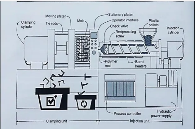
9 Kazmer (2007) has proved that, injection moulding process is generally set up by process flow which is includes plastication, injection, packing, and cooling process. First stage is plastication; during this stage molten polymer is plasticized from any solid form of pellets or granules which are fed hopper go down into heating chamber. Then, the material is heating up into molten state by heating up the barrel using heat conduction generated by the barrel heater. Next is injection stage where the molten polymer is forced out by plunger or screw to filling up the mould cavity. The molten polymer is injected down from barrel then travels through a feed system, went through gates and runner to fill up the closed mould cavity.
After the mould cavity is filled up, next is packing stage where it provides the molten polymer to cool down and contracts towards wall of mould cavity. Last stage is cooling stage, where the polymer is in rigid shaped and ready for injection step. Then, the moulded part is safely removed from mould cavity by injecting it out. Figure 2.1 below is schematic diagram for injection moulding machine processing a plastic material (Kazmer, 2007).
[image:23.595.169.484.432.640.2]
10
2.4 Mould
The essential part of producing an accurate and high quality of final part in injection moulding process is depending on type of mould used. It is important for designer to recognize the properties of the mould parts which will be determining on what type of plate design to be used in the process. Each of family mould is custom-made as they are newly made to meet needed on different design (Chana, 2013). Geometry and tolerances of product given is the main factor which has a great influence in deciding on the type of mould to be used.
Mould is generally made up from wear resistance materials such as tool steels, stainless and also aluminium. It is because injection moulding process is mass production as the mould will be use repeatedly. This type of material also equipped with any narrow geometry design on part where they are more prone to wear, damage, and undergo deformation during the process.
There are two type of mould design which is two-plate mould and three-plate mould. Both design give out different responses towards the production and also give a great influence towards input parameters.
2.4.1 Three Plate Mould
Three-plate mould design is upgrade design from two-plate design. There are three mould sections which move relative to each other (Kazmer, 2007). Each section can consist of more than one plates. Three-plate mould design is more versatile with placement of gate whether on top or bottom part at any point of surface.