Abstract: Propeller Boss Cap Fins (PBCF) is an energy saving device which is used widely to improve propulsion efficiency and save energy (fuel consumption). This paper presents the characteristics of propeller with PBCF and the comparison of the propeller with and without PBCF in terms of hydrodynamics by Computational Fluid Dynamic (CFD) method. The Potsdam propeller model is calculated and validated. Then using this validated CFD setup to calculate the Potsdam propeller with PBCF. The solver using in this research is Star CCM+
Index Terms: CFD, Hydrodynamics, PBCF, Ship propeller
I. INTRODUCTION
Today, there has been an increase in requirement for new-built ships about saving energy and reduce CO2 emission. In 2010, the Maritime International Organization (IMO) has given the Energy Efficiency Index (EEDI) [6] to measure the amount of CO2 that a ship emits in relation to the goods transported. Therefore, the solution to reduce EEDI must be given by the ship designers. One of the solutions is using the high efficiency propulsion system. The Propeller Boss Cap Fins (PBCF) is one in many energy-saving devices which have been used widely in the world. This is a device which replaces the traditional propeller cap, to improve propeller efficiency and reduce the hub vortex behind the propeller. This device has used for more than 3000 ships in the world [1].
Today, the development of computational resources has helped the designers and researchers solve many complicated ship hydrodynamics problems using Computational Fluid Dynamics (CFD) method. Recently, The CFD method by solving Reynold Averaged Navier Stokes Equation (RANSE) becomes more popular within ship design offices and researchers because it can give high accuracy result with reasonable computational time. This saves cost and time compared to traditional method by testing in towing tank. Moreover, the CFD method can perform the calculation in full scale, then directly giving the hydrodynamics results such as ship resistance, propeller thrust and so on. In traditional method, we have to interpolate from the results of experiment in model scale.
In terms of methods for propeller calculation and propeller designs, there are many approaches that are available: such as lifting line, lifting surface, boundary
Revised Manuscript Received on April 06, 2019.
Chien Manh Nguyen, Ship Building Department, Vietnam Maritime University, Hai Phong, Vietnam.
Quynh Thi Thu Nguyen, Ship Building Department, Vietnam Maritime University, Hai Phong, Vietnam.
Tu Ngoc Tran, Ship Building Department, Vietnam Maritime University, Hai Phong, Vietnam.
element method (BEM) and CFD (including RANSE, LES, DNS) [7], [8], [9], [10]. However, as mentioned above, to analyze the flow around the propeller, RANSE method is most popular and used widely.
Therefore, this paper presents the result of hydrodynamics calculation for propeller with PBCF device by RANSE CFD method, in comparison with normal propeller (without PBCF). The authors will show the advantages of PBCF and give the recommendation for designers and researchers for designing and optimizing PBCF.
II. INTRODUCTIONOFPBCFANDPROPELLER
OPENWATERTEST
A. Introduction of PBCF
PBCF has developed since 1987 by Muisui O.S.K.Lines, West Japan Fluid Engineering Laboratory and Mikado Propeller (Nakashima Propeller). PBCF is a cap with blades and numbers of blades of PBCF are equal the numbers of propeller blades (Figure 1).
[image:1.595.305.545.477.676.2]In normal condition, the fluid flow behind propeller is twisted and generating the large vortex called “hub vortex”. In principle, when the PBCF is replaced the cap of propeller, the hub vortex decreases significantly, subsequently, the thrust and propeller efficiency increases.
Figure 1. Picture of PBCF [1]
B. Propeller Open Water Test
Propeller open water test is an experiment carrying out in towing tank to determine the hydrodynamic characteristics of the propeller, including thrust coefficient KT, torque coefficient KQ and open
water efficiency η0. The propeller with PBCF is also tested in towing tank with
Hydrodynamics Calculation of Propeller with
PBCF By RANSE CFD Method
similar process as normal propeller. However, to assess the influence of PBCF to the fluid flow behind the propeller, the open water test is carried out in a “reversed method”. Particularly, for normal open water test, the cap is put in front of the propeller to have a uniform flow coming to the propeller (Figure 2). In “reversed open water test”, the PBCF is put behind the propeller, same as in the configuration of propeller in operating condition (Figure 3).
[image:2.595.332.526.52.229.2]Therefore, the authors use same configuration for CFD setup, to determine the hydrodynamics characteristics of propeller with PBCF
Figure 2. Normal Open water test [1]
Figure 3. Reversed Open water test for PBCF [1]
III. NUMERICALMETHOD
A. Geometry of Selected Propeller
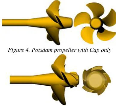
The propeller that the authors use to calculate in this paper is Potsdam propeller [2]. This propeller has tested in towing tank and there are many experimental result available, which is provided by Schiffbau-Versuchsanstalt Potsdam (SVA Potsdam) [2]. Table 1 presents the geometry parameters of Potsdam propeller, and its shape is shown in Figure 4. The authors have changed the original geometry provided by SVA by replacing the propeller cap with new one. The new cap is the hub of PBCF without blades. Thus, it is easy and convenient to access the influence of PBCF to the propeller performance.
The PBCF in this paper is designed in Rhinoceros software (the 3D CAD software), with 5 blades, radius of 0.043m (43mm) and the inclination angle of PBCF blades is 56 degree (Figure 5).
Table 1. Geometrical parameters of Potsdam propeller [2]
Geometrical Parameters Units Values
Diameter D m 0.25
Expanded Area AE/A0 - 0.778
Hub ratio Dh/D - 0.3
Numbers of blades Z - 5
Pitch ratio P0.7/D 1.635
Rotation direction - - Right
Figure 4. Potsdam propeller with Cap only
Figure 5. Potsdam propeller with PBCF
B. Simulation Setup
[image:2.595.65.273.185.362.2]To simulate and calculate the hydrodynamics characteristics propeller in open water, the authors use commercial solver Star-CCM+. The calculation domain is a cylinder with diameter of 2.5 meter (10 times propeller „s diameter), length of 3.5 meter; distance from propeller to outlet is 3 meters (Figure 6). The area behind propeller is refined to capture the vortex and streamlines behind the propeller (Figure 7). This refinement increases the mesh size significantly. In this setup, the authors use 8.64 million cells for calculation of propeller without PBCF and 8.72 million cells for the one with PBCF
Figure 6. Calculation domain
Figure 7. Local refinement around propeller
The rotating motion of propeller is simulated by Rotating Reference Frame method.
[image:2.595.315.537.406.723.2]giving accuracy result [7].
The boundary condition is as follows: the inlet (the boundary which is in front of the propeller) is set as “velocity inlet” with value of flow velocity to the propeller. The behind boundary is set as pressure outlet, and the around boundary is set as symmetry plane. The kw-SST turbulence model is chosen, with “all wall treatment” selection for wall distance Y+.
IV. CALCULATIONRESULT
A. Calculation Result for Normal Propeller
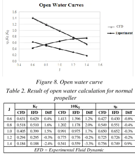
[image:3.595.320.534.261.334.2]As discussed above, the calculation results of Potsdam propeller (with normal setup for open water) will be compared with experimental result to validate the CFD setup in Star CCM+. The authors perform the calculation with advance coefficient (J) by 0.6, 0.8, 1.0, 1.2 and 1.4. The result is presented in Figure 8 and Table 2. The result shows that the CFD calculation is very close to the experimental result in towing tank, with the differences of open water efficiency is just below 1%. Thus, this CFD setup can use for calculation of propeller with PBCF. The calculation result of propeller with PBCF is presented in the next part, in comparison with propeller without PBCF.
[image:3.595.60.285.350.612.2]Figure 8. Open water curve
Table 2. Result of open water calculation for normal propeller
CFD EFD Diff CFD EFD Diff CFD EFD Diff
0.6 0.631 0.629 0.4% 1.413 1.396 1.2% 0.427 0.430 -0.8% 0.8 0.518 0.510 1.6% 1.202 1.178 2.0% 0.549 0.551 -0.4%
1.0 0.405 0.399 1.5% 0.991 0.975 1.7% 0.650 0.652 -0.3% 1.2 0.294 0.295 -0.3% 0.775 0.776 -0.2% 0.725 0.726 -0.2%
1.4 0.184 0.188 -2.4% 0.541 0.559 -3.3% 0.756 0.749 0.9%
J KT 10KQ
EFD = Experimental Fluid Dynamic η0
B. Calculation Result of Propeller with PBCF
The calculation result of propeller with PBCF is shown in Table 3, in comparison with propeller without PBCF. The result of thrust coefficient (KT), Torque coefficient (KQ) and open water efficiency (η0) are calculated for whole system including: propeller, hub, and PBCF.
Table 3. Calculation result of propeller with PBCF
with PBCF
without PBCF
% Diff
with PBCF
without PBCF
% Diff
with PBCF
without PBCF
% Diff
0.6 0.585 0.578 1.3% 1.414 1.427 -0.9% 0.395 0.387 2.2% 0.8 0.481 0.475 1.3% 1.189 1.194 -0.5% 0.515 0.506 1.8%
1.0 0.365 0.364 0.4% 0.956 0.962 -0.6% 0.608 0.602 1.0% 1.2 0.256 0.256 -0.1% 0.733 0.732 0.0% 0.667 0.667 -0.1% 1.4 0.147 0.149 -1.4% 0.499 0.498 0.2% 0.656 0.667 -1.6%
J
KT 10KQ η0
We can see from the Table 3 that the open water efficiency of propeller with PBCF increases by around 2% for J = 0.6 to 1.0 and decreases for J = 1.2 and 1.4. This can be explained that the PBCF is not optimized design for the range J from 1.2 to 1.4.
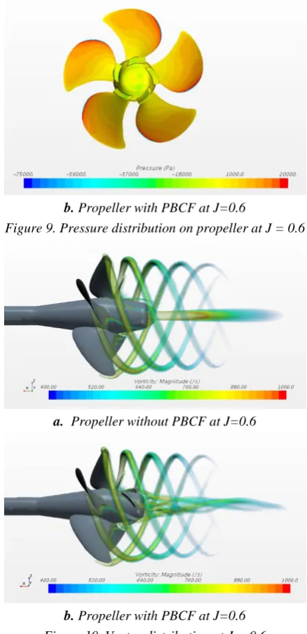
However, the most important influence of PBCF here is that the change of flow behind propeller with PBCF, particularly the streamline and pressure distribution on propeller blades and hub (Figure 8,9 and 10). Figure 8 shows the significant decrease of hub vortex of propeller with PBCF at J = 0.6, also, the flow is distributed more uniformly. This decrease of hub vortex makes the open water efficiency and thrust coefficient increase at J = 0.6. Additionally, the decrease of hub vortex helps reduce the vibration behind ship and rudder erosion. This can be seen by stream lines distribution on Figure 8.
a. Stream lines for propeller without PBCF at J=0.6
[image:3.595.316.537.361.469.2]b. Stream lines for propeller with PBCF at J=0.6
Figure 8: Stream lines for propeller at J = 0.6
For pressure distribution, there is a decrease in pressure at the center of propeller cap for the case without PBCF. Whereas, with PBCF, the pressure distribution is more uniformly in this area (Figure 9). Figure 10 shows the vortex generated by propeller blades. Once again, the hub vortex in case of propeller with PBCF is reduced and diverged.
[image:3.595.319.539.553.692.2] [image:3.595.61.284.699.793.2]b. Propeller with PBCF at J=0.6
Figure 9. Pressure distribution on propeller at J = 0.6
a. Propeller without PBCF at J=0.6
[image:4.595.64.288.185.751.2]b. Propeller with PBCF at J=0.6 Figure 10. Vortex distribution at J = 0.6
a. Stream lines for propeller Without PBCF at J=1.4
b. Stream lines for propeller With PBCF at J=1.4 Figure 11. Stream lines for propeller at J = 1.4
The calculation result and the pictures of flow around propeller are well agreed with the result of Takeo Nojiri[1] Kurt Mizzi [3], Takafumi Kawamura [4], Hans Richard Hansen [5].
Looking at stream lines behind propeller at J = 1.4 (Figure 11), PBCF still makes the stream lines diverged, however, there are still much hub vortex remaining. In this case, PBCF makes the pressure differences in Pitch face and Back face of propeller decrease, leading to the decreases of propeller thrust and efficiency. Thus, if the propeller works in range J from 1.2 to 1.4, it is necessary to redesign and optimize PBCF to reduce hub vortex and increase propeller efficiency in this range.
V. CONCLUSION
A. Figures and Tables
The paper presents the calculation result of propeller with energy saving device PBCF by RANSE CFD method. The result shows that propeller with PBCF increases efficiency by 2% at some range of advance coefficient J. Most importantly, by using PBCF, the hub vortex is eliminated significantly. For normal propeller, this hub vortex is large and reduce the efficiency of system including: propeller, rudder and ship. The elimination of hub vortex also decreases the vibration on the aft of the ship and the erosion of rudder.
This calculation result is the starting step in PBCF optimization design process by parametric modelling method. Firstly, the PBCF is parametric modelled. Then, by changing the PBCF parameters, we get new PBCF design. Each design will be calculated by RANSE CFD to select the best one with highest efficiency at the working range of propeller advanced coefficient J. Optimization algorithms should be applied during this process.
The paper also shows the capability of RANSE CFD in solving ship hydrodynamic problems. RANSE CFD is able to provide the detailed pictures of flow around the ship and devices, in which the experimental method cannot do or can do but very costly
ACKNOWLEDGMENT
The authors give the gratitude to the Vietnam Maritime University and Siemens Company for supporting us in this research.
REFERENCES
1. Nojiri, Takeo & Ishii, Norio & Kai, Hisashi. (2011). Energy Saving Technology of PBCF (Propeller Boss Cap Fins) and its Evolution. Journal of The Japan Institute of Marine Engineering. 46. 350-358. 10.5988/jime.46.350.
2. SVA Potsdam Model Basin. Potsdam propeller test case. Potsdam; 2011.
4. Kawamura, Takafumi & Ouchi, Kazuyuki & Nojiri, Takeo. (2012). Model and full scale CFD analysis of propeller boss cap fins (PBCF). Journal of Marine Science and Technology. 17. 10.1007/s00773-012-0181-2.
5. Hans, Richard &, Hansen & Tom Dinham-Peren, Mr & Takeo Nojiri, Mr. (2018). Model and Full Scale Evaluation of a 'Propeller Boss Cap Fins' Device Fitted to an Aframax Tanker.
6. Lloyd‟s Register and DNV, Assessment of IMO energy efficiency measures for the control of GHG emissions from ships, MEPC 60/INF.18, 15 January 2010
7. Tu, Tran Ngoc; Chien, Nguyen Manh, Comparison of Different Approaches for Calculation of Propeller Open Water Characteristic Using RANSE Method, Naval Engineers Journal, Volume 130, Number 1, 1 March 2018, pp. 105-111(7)
8. Perali, P., T. Lloyd, and G. Vaz. Comparison of uRANS and BEM-BEM for propeller pressure pulse prediction: E779A propeller in a cavitation tunnel. in Proceedings of the 19th Numerical Towing Tank Symposium. 2016.
9. Brizzolara, S., D. Villa, and S. Gaggero. A systematic comparison between RANS and panel methods for propeller analysis. in Proc. Of 8th International Conference on Hydrodynamics, Nantes, France. 2008. 10. Molland, A.F., S.R. Turnock, and D.A. Hudson, Ship resistance and
propulsion. 2017: Cambridge university press.
AUTHORSPROFILE
Chien, Manh Nguyen received the MSc degree (2015) in Naval Architecture from University of Liege, Belgium; and MSc degree (2015) in Applied Mechanics specialization in Hydrodynamics from Ecole Centrale de Nantes, France. He is a lecturer and researcher at Department of Shipbuilding, Vietnam Maritime University. His current interests include Ship hydrodynamics, propeller hydrodynamics, and application of Computational Fluid Dynamic (CFD) in ship design.
Quynh, Thi Thu Nguyen received Bachelor of Engineering in Naval Architecture in 2002 and MSc degree in Naval Architecture in 2007 from Vietnam Maritime University. Currently, she is a lecturer at Department of Shipbuilding, Vietnam Maritime University. Her interests include optimization calculation of ship design and ship equipment.
![Figure 1. Picture of PBCF [1]](https://thumb-us.123doks.com/thumbv2/123dok_us/8213379.263709/1.595.305.545.477.676/figure-picture-of-pbcf.webp)