University of Southern Queensland
Faculty of Health, Engineering and Sciences
Design of an Optical Access Engine and
Pneumatic Head Clamp
A dissertation submitted by
Gabriel Martin
in fulfilment of the requirements of
ENG4111 and 4112 Research Project
towards the degree of
i
Abstract
This dissertation entails the design of a pneumatic clamp for the USQ optical access engine. A literature review on Optical engines and the relevant theory was conducted. During the design work, consideration of feasibility was critical to ensuring that the operation of the clamp would be sound, based on the current engine design by Kevin Dray. The focus of the design work involved identification and segregation of the components into different areas of analysis. The main components were analysed and the results for these subsections have been presented in this dissertation.
3D modelling software was utilized to assist in the design process. Tools on this software provided insight into the response of different components when place under certain loading and thermal conditions. It was found that the use of a standard 150 psi air compressor would indeed be sufficient to supply the pressure required to seal the combustion chamber during engine operation. The controlling element for the system was a proportional valve. The dynamics of the system based on valve positon have been described. The true valve response was neglected in the analysis as they typically responding almost instantaneously.
ii
University of Southern Queensland
Faculty of Health, Engineering and Sciences
ENG4111 & ENG4112 Research Project
Limitations of Use
The Council of the University of Southern Queensland, its Faculty of Health, Engineering and Sciences, and the staff of the University of Southern Queensland, do not accept any responsibility for the truth, accuracy or completeness of material contained within or associated with this dissertation.
Persons using all or any part of this material do so at their own risk, and not at the risk of the Council of the University of Southern Queensland, its Faculty of Health, Engineering and Sciences or the staff of the University of Southern Queensland.
iii
Certification
I certify that the ideas, designs and experimental work, results, analyses and conclusions set out in this dissertation are entirely my own effort, except where otherwise indicated and acknowledged.
I further certify that the work is original and has not been previously submitted for assessment in any other course or institution, except where specifically stated.
Gabriel Martin
iv
Acknowledgements
I would like to thank the University of Southern Queensland for the opportunity to be able to study and learn about engineering. The University of Southern Queensland has provided the facilities and resources to help me through my studies. Of this I am grateful.
I want to thank my supervisor, Professor David Buttsworth, for assisting me during my project work. I also want to thank staff at Parker Hannifin and their staff for advice and tips with my design. In particular I want to thank Michael Spain, who took the time to chat during work hours about my design.
v
Table of Contents
Abstract
iAcknowledgements
ivChapter 1 – Introduction
11.1 Purpose of OA Engines
21.2 Motivation for Project
2
1.3 Project Specification
3
Chapter 2 - Literature Review
42.1 Basics of Internal Combustion (IC) Engines
4
2.2 Research – OA Engines
5
2.3 Material Review
10
2.4 Pneumatics vs Hydraulics
16
2.4.1 Air Compressors 18
2.4.2 Reciprocating Compressors 18
2.4.3 Rotary Compressors 19
2.4.4 Dynamic (flow) Compressors 19
2.4.5 Air Supply System 19
2.4.6 Coolers 20
2.4.7 Dryers 20
2.4.8 Air receivers 20
2.4.9 Actuators 20
2.5 Cylinder Head Review
22Chapter 3 – Methodology
243.1 Background Research
24
3.2 Concept to Design – Lower Cylinder Barrel Modification
243.2.1 Conceptualisation Phase 24
3.2.2 Design 26
vi 3.2.4 Hole/Shaft tolerances – System of Fits 29
3.3 Feasibility
30
3.3.1 Pressure-supply limitations 30
3.3.2 Part availability 31
3.3.3 Machining 31
3.3.4 Sustainability 32
3.3.5 Ethics 32
3.3.6 Safety 33
3.3.7 Resources 34
3.3.8 Budget 35
3.3.9 Risk Assessment 35
Chapter 4 – Design – Components and Mathematical Principles
374.1 Components
374.1.1 Actuator base 38
4.1.2 Actuator piston 38
4.1.3 Guide rings 38
4.1.4 O-ring seals 48
4.1.5 Optical Ring 55
4.1.6 Head gasket 58
4.2 Design Factors
61
4.2.1 Friction 62
4.2.2 Wear 63
4.2.3 Fatigue 64
4.3 Actuator Dynamics
65Chapter 5 – Results and Discussion
725.1 Actuator Dynamics Results
725.2 O-ring Results
76
5.2.1 O-ring squeeze 77
5.2.2 O-ring Friction 78
5.2.3 O-ring FEA 80
5.3 Guide Ring Results
81
vii
Chapter 6 - Conclusion
876.1 Recommendations for Future Work
87References
89Appendices
93Appendix A – Project Specification
93
Appendix B – Work Place Health and Safety Act 2011 – pp. 22-28
94Appendix C – Properties of Cast Iron
101
Appendix D – Table of Mechanical Properties of selected ceramics and glasses 102
Appendix E – Properties of transmissive optics materials
103
Appendix F – Tables of glass fibre materials
104
Appendix G – Table of Sapphire properties
107
Appendix H – Properties of thermoplastics
108
Appendix I – MATLAB dynamics code for actuator
112
Appendix J – Parker ECI Metal C-ring Internal Pressure Face Seal data
115
Appendix K – MATLAB code for bearing deflection in edge-loaded case 118
Appendix L – MATLAB code for seal compression
120
Appendix M – MATLAB code for discharge
122
1
1
Introduction
Combustion is a phenomenon encountered by many people of varying backgrounds, whether that be in the area of research or simply for private use. It has recently generated some concern over the issue regarding non-renewable energy resources and the depletion of such and has led to a dire situation in which energy alternatives are rigorously being considered. With the current increase in transportation demands due to population growth, just one of the main factors calling for a need in alternatives, such alternatives will soon be essential if regular human activities are to continue.
Analysing combustion processes is key to developing our current knowledge of the phenomenon and hopefully the research that is undertaken will advance this knowledge into a further phase.
One such method of analysing combustion processes is by using lasers to scan the interior of engine cylinders. By applying the principles of refractometry an analyst is able to determine how the combustion cycle function within an engine cylinder. This insight then produces an image on a computer monitor that takes a transient snap-shot of the entire region of the cylinder area. Various images may be taken and compared with other different images that depict different parts of the engine stroke cycle. More specifically, Optical Access (OA) engines enable the diagnosis of fluid (fuel vapour) flow and combustion characteristics. Thus it is critical that an OA engine replicate the operation of a typical Internal Combustion (IC) engine as accurately as possible in order to provide proper insight to these characteristics.
2
1.1 Purpose of OA Engines
The purpose of an OA engine is to better understand engine performance and emissions. Laser diagnostics with optical access enable the use of methods to analyse these aspects of the IC engine. Some alterations to the typical operation of an IC engine must be made in order to produce good operating conditions. One alteration is to use what is called a skip-fired mode, where the injector is skip-fired once every 8th cycle. The purpose of this is to reduce
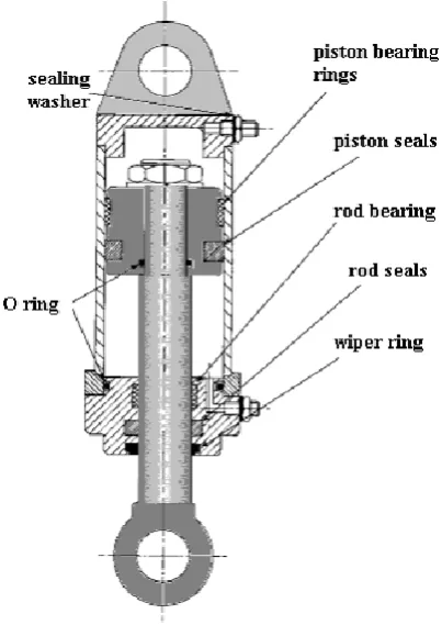
[image:10.595.196.398.247.532.2]the required frequency of window cleaning and to reduce the risk of window failure due to the high thermal and mechanical stresses.
Figure 1 – Schematic of typical air cylinder (Dunn)
1.2 Motivation for Project
3
1.3 Project Specification
The Project Specification, which is attached in Appendix A, will essentially form the marking rubric for this dissertation. As mentioned, the primary focus of the project was to design a pneumatic head clamp. A question this raised was “Why use pneumatics over hydraulics?” One reason for using pneumatics is that pneumatics exhibit faster reactions to forces than hydraulic fluids can. This characteristic is desirable when regarding time as a performance-influencing factor. Capital costs for pneumatic systems are also generally much cheaper than that of hydraulic systems. The degree to which time is minimised may be minute however every aspect of time saving is an important consideration.
Project Commissioning
This stage can only be initiated once the design work, budget and material list have been finalised. Due to time constraints the cost analysis and material list could not be completed.
Consequential Effects
4
2
Literature Review
2.1 Basics of Internal Combustion (IC) Engines
For the sake of simplifying what is a very complicated system, here is a brief overview of what an IC engine is, what it does, what materials it is made from and what research is being done to make them cleaner and more efficient.
An IC engine uses the phenomena known as combustion to produce power in order to make a machine do work. Work in the scientific realm is defined as the product of Force and Displacement. In other words, Work can only be achieved if a particle is moved over any distance as a result of a force being applied to it. If either the force being applied or the distance covered have a value of zero, then there is no work being done. Subsequently, this work or power is then harnessed and directed through a transmission and drivetrain. These systems are what deliver the final ‘drive’ to what is most often the case the wheels of the vehicle which the engine is powering.
This power is greatly influenced by factors such as those that pertain to combustion chamber geometry, the number of valves, ignition timing and fuel type.
Engine heat
5
Engine Loads
A ‘load’ is also known as a force. A force is a minute part of common engineering knowledge. Specifically, an engine load is a force created by moving components in an engine. It is therefore natural that an engine vibrates due to the movement of components. These vibrations can be categorised it internal and external vibrations. Kevin Dray (2014) has already performed vibrational analysis on the internal components of the engine which is subject here. For the purpose of the pneumatic clamp, it was assumed that vibrations would be borne fully by the engine mounts at the base of the engine (outside of the scope of this project). However, the combustion pressures (and temperatures) will be considered as some of the contributors to the loads considered in this project.
2.2 Research - OA Engines
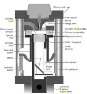
[image:13.595.198.391.528.742.2]There are various designs of OA engines that have been built in the past. Some design approaches have been more popular and have been implemented into other designs. For example, one common approach of gaining optical access to an engine cylinder is by using a Bowditch piston. A Bowditch piston consists of a fixed mirror inclined at 45-degrees to the horizon, situated underneath the moving piston. The advantage of having this arrangement is that a visual inspection of up to about 75% of the combustion chamber can be achieved. This method of gaining access superseded that of having an L-shaped engine head which had valves positioned in the block instead of the head.
6 Figure 3 – Schematic of OA engine cross section with Cummins B-series block
(Musculus 2015)
Some key features of a typical modern optical access engine are outlined below.
- Optical access through flush-mounted spacer-ring and spacer-ring curved window. Windows usually comprise of fused silica or sapphire. Fused silica offers superior UV light transmission while sapphire provides excellent hardness and strength. - Lowered piston ring pack to prevent scratching of spacer-ring window.
- Piston rings made from self-lubricating polymers in order to eliminate or at least minimise sooting.
- An optical piston crown, usually made of quartz or sapphire.
- A means of rapidly separating engine head from engine block, usually by the use of hydraulic or pneumatic cylinders.
- A mirror inserted inside elongated piston at 45˚ to aid in optical access from bottom of cylinder.
- Elongated cylinder with vertical slot to allow optical access from bottom of cylinder and replacement of mirror.
7 - A strong, stiff connection of the cylinder head to the crankcase, usually via long support posts. Figure 2 illustrates the use of a strong back to which the support posts are clamped.
There are also some designs that have variations of the main features described above. One variation is a short transparent ring with 360˚ viewing, as opposed to the spacer ring with crown windows. The disadvantage with this arrangement is that peak pressure is limited to about often to about 50-100 bar. Another different design feature is a full-height transparent cylinder liner with piston rings being allowed to slide over the liner. Once again, this provides almost complete optical access to the entire cylinder stroke, however, operating conditions are consequently highly constrained due to the liner fragility. Other unique design variations for the piston include a specially shaped transparent piston crown (rather than being flat) for producing a particular combustion characteristic and also pistons with no crown window (Musculus 2015).
Other modifications are suggested such as making the bottom of the piston bowl flat rather than contoured and situating the compression ring lower to allow for placement of windows in the piston bowl-rim. Clearance would need to be given to prevent rubbing of the piston-crown windows and as a result clearance volume would be increased, thus reducing the compression ratio. Intake mixture pressure and temperature may also have to be increased to be more indicative of a true IC engine (Jaaskelainen 2010).
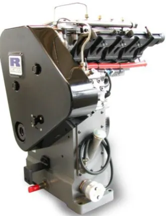
Automobile company Lotus have developed their own version of the OA engine. The cylinders and pistons are made from glass which enables good laser diagnostics. This engine is capable of running up to 5000 rpm. It too utilises a Bowditch Piston arrangement. The piston crown window is made from Sapphire while the glass cylinder is made to be easily removable. The upper crankcase employs a hydraulically operated platform that allows removal of optical components. A quick release liner is included and there are primary and secondary balance shafts (LOTUS PLC 2016).
8 Figure 4 – Lotus SCORE engine (Morgan 2008)
[image:16.595.215.381.443.659.2]9
Application of OA Engines
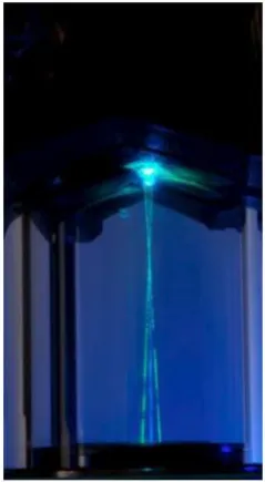
OA engines serve as a tool for diagnosing and analysing combustion and fuel and air mixture flow patterns. Lasers are critical to optical diagnostics. There a variety of methods that are used depending on what the research aims to achieve. The first method is called Laser Doppler Anemometry (LDA). Fluid velocities at a point are measured where two laser beams intersect. Full flow field velocities can also be attained using this method, however, these specific points have to be measured by the laser beams separately.
The next method is Particle Image Velocimetry (PIV). With PIV, two laser sheets are project into the combustion chambers at slightly separate times. The flow is ‘seeded’ with particles and when the laser is projected onto these particles they are illuminated, at which point a camera captures their path. Phase Doppler Anemometry (PDA) is a modified form of LDA. As well as determining the velocities of fluids at certain points, like in LDA, the size of droplets can also be found with PDA. PDA incorporates a fast camera and flash light system to enable the viewer to depict the shape of fuel droplets.
[image:17.595.237.357.526.744.2]Laser Induced Fluorescence (LIF) is another method employed for analysing fuel that is in a vapour state. A laser sheet with an ultra-violet wavelength is projected into the chamber, causing the fuel vapour to fluoresce. The camera with a suitable optical lens captures this fluorescence, indicating the fuel vapour concentrations in the chamber during ignition (Morgan 2008). Similarly, soot concentrations can also be established for a particular instance in time, using a method called Laser Induced Incandescence (LII) (LOTUS PLC 2016).
10 Figure 7 – Velocity field obtained from PIV analysis (Wikipedia the free Encylopaedia 2016a)
2.3 Material Review
OA engines comprise of some of the typical materials seen in production IC engines yet there are some components of the OA engine that require implementation of unique materials. Ordinary IC engines, for a long time, have typically used either an Iron casting or Aluminium alloy for the block and head. It should be emphasised that the materials addressed here provide a broad overview of materials in IC and OA engines. However their combination with each other and other materials was noticed during the design phase. For example, when researching bearing supplier’s websites and catalogues for bearing materials, combinations of Graphite, Carbon and PTFE were found for one particular bearing compound.
The cylinders in the Champion MTO II air compressors are cast iron and hard chrome-plated. The engine also has PTFE guide rings (Champion). As will be shown in the latter sections of this dissertation, the air cylinder is analogous to the design of the pneumatic clamp. Following is a brief review of some common materials that can be found in optical engines.
Cast Iron
11 4 percent), Silicon and Manganese. Sometimes additional alloying elements are added. The physical properties of a cast iron component are largely influenced by the cooling rate during solidification (Juvinall & Marshek 2012).
As engines are cyclic, dynamic machines that naturally cause wear on their components, it is worth describing some of the characteristics of Cast Iron in terms of its Fatigue Strength. Appendix C contains some tabulated data on Cast Irons and their fatigue strengths.
PTFE
Polytetrafluoroethylene (PTFE or Teflon) is a thermoplastic polymer. Specifically, PTFE is party of the fluoroplastic family, meaning it contains Fluorine atoms within its molecular structure, as shown below. Generally, fluoroplastics have excellent chemical and electrical resistance, low friction and stability at high temperatures, with a low moderate tensile strength(Juvinall & Marshek 2012). Contrary to cast iron, PTFE is difficult to manufacture due to its resistance to easy flowing, even above melting point. PTFE is formed by the polymerisation of the colourless, odourless gas, tetrafluoroethylene (C2F4). To obtain this
gas, hydrogen fluoride (HF) is reacted with Chloroform (CHCl3). This reaction forms into Chlorodifluoromethane (CHClF2). Then, by heating CHClF2 to a range of 600-700 ˚C,
tetrafluoroethylene is obtained in the form of monomers. These C2F4 monomers are
emulsified in water and are polymerised to form PTFE polymers (Editors of Encyclopaedia Britannica 2015).
Polymerisation in simple terms is the formation of chains of molecules or monomers. These chains are formed by the sharing of free, unpaired electrons between two monomers. Thus, a ‘polymer’ is an arrangement of multiple monomers linked together via a chemical reaction. Addition polymerisation and condensation polymerisation are the two types of polymerisation that can occur.
Figure 8 – Structure of PTFE molecule (Editors of Encyclopaedia Britannica 2015)
Addition polymerisation can only occur if there is a sufficient level of heat, pressure and catalysts available. A monomer, such as Ethylene (C2H4) for example, contains a double
12 presence of the heat, pressure and catalysts to form a single covalent bond. This results in the ends of the monomers becoming free radicals or the Carbon atoms allowing for an electron to become unpaired. These ‘open ends’ then join to other identical molecules with the same free radicals to form the long polymer chain.
Condensation polymerisation occurs in a similar fashion to addition polymerisation, only that a by-product of the reaction is ‘condensed’ out while two newly formed monomers combine to create the chain. Many polymers are formed by complex monomers, which are often produced through a condensation polymerisation process. Polyimide is an example of a complex polymer (Askeland & Phule 2006).
Polyimide
Polyimides can be either thermoplastic or thermosetting. For the thermosetting type polyimide, properties attributable include thermal stability, chemical resistance and excellent mechanical properties including low creep and high tensile strength. This polymer can also be compounded with other materials to further improve certain qualities. For example, to improve tribological properties, polyimide may sometimes be combined with graphite, PTFE or molybdenum sulphide depending on the design objective (Wikipedia the free Encyclopaedia 2016). By compounding PTFE with Polyimide Powder (P84) creep values are improved to an even greater degree (HP Polymer Inc.). This material has been applied within aerospace and automotive domains.
Aluminium
13
Quartz
This is a clear, crystal-structure material that is often used for the optical access points of an OA engine. Quartz is piezoelectric, meaning that it is able to create an electrical current when pressurised. The negative aspect of Quartz is that it is fairly fragile and breaks in a similar manner to glass due to its microstructure(Bates). Quartz can be classified as a type of glass but with specifically different properties to the more common kind which is called ‘crown glass’. Borosilicate glass Schott BK7 is a very common crown glass as used in precision lenses. Overall quartz allows for excellent transmission in the ultraviolet wavelength and a comparatively low coefficient of thermal expansion. It has also a higher melting point than most conventional crown glass types (Precision Cells Inc. 2010).
Fused Silica
Much of the literature reveals that fused silica is also a popular choice of material for optical components. Fused Silica is derived from pure SiO2. Fused Silica has a high melting point
and dimensional changes during heating and cooling are small (Askeland & Phule 2006). Probably most notable from the table in Appendix E is the fact that Fused Silica, amongst other common optics materials, exhibits a much lower linear expansion coefficient than the other materials. This is one very desirable feature for an optical engine (ASM International 2011).
Graphite
14 Figure 9 – Mechanical Properties of Aluminium alloy vs Graphite (Heuer)
Figure 10 – Tensile strength of Aluminium alloy and Graphite with respect to temperature (Heuer)
Performance improvements can be made on the basis of the advantages of Graphite, such as lower weight and less noise. Graphite without fibre reinforcements is also known as Carbon(Heuer).
Sapphire
15 in practice. Data based on the mechanical properties of Sapphire can be found in Appendix G.
The failure mechanism of Sapphire is very similar to that of glass due to its brittle quality. Thus the overall strength of a component made from Sapphire is highly dictated by the surface finish as well as a number of other factors(Bates).
Solid Film Lubricants
Solid film lubricants are a recent innovation that have evolved the way in which machinery components are lubricated. Rather than the typical oil-based lubricants being used, a solid film lubricant essentially deletes a liquid lubricant from the bearing component interface, removing the possibility of soot forming and/or excessive oil build-up on optical surfaces. These materials may also be added or alloyed into the component during its manufacture. The more common types of dry/solid film materials include: Molybdenum Disulfide (MoS2 or Moly), Polytetrafluoroethylene (PTFE), Graphite, Boron Nitride, Talc, Calcium Fluoride, Cerium Fluoride and Tungsten Disulfide (Noria).
Figure 11 – Microstructure of Molybdenum Disulfide (Noria)
16 latter section of this dissertation, they are commonly sourced from large seal and bearing suppliers, such as Parker Hannifin Corporation.
The disadvantage with using oil-free machines is that heat generated between surfaces where friction exists is greater than that of surfaces with liquid lubrication (CarsDirect 2012).
2.4 Pneumatics vs Hydraulics
Air is under unlimited supply and it can be easily sourced from the environment. Storage and transportation of certain types of air/gas (i.e. Nitrogen) is done with minimal difficulty. Air is also clean and non-volatile. Construction of pneumatic componentry often brings forth relatively simple-shaped parts with simple manufacturing processes so costs is usually low with such parts (air pistons/rams). Another major advantage with pneumatic systems is that they consist of safety systems. These safety systems may be relief valves.
Contrarily, systems that utilise air as a source of pressure/power may be disadvantaged in some areas. One example is the fact that the quality of the working fluid has to be of a high standard in order for the mechanisms to operate without premature failure or deterioration. The presence of any dirt or moisture in a system that is not properly sealed or has not been handled correctly may result in excessive wear, worn seals and/or damaged compressors and pumps. Consequently pneumatic systems must have air filtration and air drying systems implemented. Another obvious disadvantage with air is that it is compressible – this is difficult to track and consequently some mechanisms may not always attain a uniform and constant speed while in operation.
Some other disadvantages with pneumatic systems is due to the general properties of air. In regard to temperature pneumatic systems are unaffected up to about 120 degrees Celsius. Another issue is with the force requirement. Because of its compressibility, the working pressure of air is effective only up to about 6-7 bar (600-700 kPa). This typically results in a force output between 20 and 30 kN (obviously depending on the surface area under pressure). Other minor issues include noise (when exhaust air is released) and cost of transmitting air as a power source (University of Southern Queensland 2014).
17 positive traits and their limitations. Hydraulic fluid can supply a greater amount of force in a system, however, air requires less sophisticated pipework and does not pose a health hazard should there be a pipe leak. There are other differences that also set hydraulics and pneumatics apart. Yet, for this application, where large load capacities are not necessary and simplification of the system is desired, along with a minimal cost to the end user, air seems to be a good choice as the power source.
[image:25.595.179.480.262.622.2]A pneumatic system involves several stages before the actuator is activated by the power source. According to Workbook 2 from System Design (University of Southern Queensland 2014) here are the main stages of the travel of air:
Figure 12 – Levels of a pneumatic system (University of Southern Queensland 2014)
18
2.4.1 Air compressors
The main categories of air compressors fall into either positive displacement or dynamic.
Some examples of positive displacement compressors include reciprocating and rotary compressors. The above types of air compressors will now be discussed in detail.
A factor that is very important to air compressor selection is the ‘duty-cycle’. Simply defined, duty-cycle is the percentage of total running time that the compressor is running at full load. Certain compressors need to cool down for a certain amount of time depending on their duty-cycle value. Duty-cycle can be defined by the simple formula D=R/T, where R is run time before cool-down and T is total running time. Typically compressors have their duty-cycles graded according total running times of 10 minutes (TruckSpring Times 2011). So, for example, where a compressor has a duty-cycle of 30%, D will be 0.3, T is always 10, and thus R has to be 3. Alternatively, a compressor with a duty-cycle of 30% has to cool down for 3 minutes out of every 10 minutes of use.
2.4.2 Reciprocating Compressors
The main categories for a reciprocating type fall into two main sub-categories – piston and diaphragm compressors. Compressors can be either single-acting or double-acting. They can also require multiple stages. A single-acting compressor has an inlet and outlet valve on one side of the piston/diaphragm (usually on top). In a double-acting compressor, inlet and outlet valves will be situated both on top and below the piston. There is no large difference between a piston and diaphragm type compressor. What is different with a diaphragm compressor is that, as the name suggests, a flexible diaphragm, driven by a piston beneath, pumps the fluid in and out of the system, rather than just a piston alone. Diaphragm compressors are more commonly implemented as water pumps (University of Southern Queensland 2014).
A compressor with multiple stages pumps fluid (air) up to higher pressures between differently sized cylinders. These systems usually have intercooling included due to the adiabatic effect.
19 cost is much less than that of pressure-lubricated compressors. Splash-lubrication is much more simple in that a dipper is added to the connecting rod of the piston and, as it rotates, splashes oil onto the moving components. Contrarily, pressure-lubricated systems use built-in oil pumps to force oil to specific components more efficiently.
2.4.3 Rotary Compressors
These come in the form of rotary vane, rotary screw and Roots blower compressors. Rotary vane compressors have some advantages over reciprocating compressors, including low noise level, low vibrations, small size and pulsation-free airflow. Their output pressures vary slightly compared to reciprocating compressors but the difference is negligible. One downside is that oil is injected into the air supply, meaning that the output source of pressurised air will contain a considerable amount of oil, especially when compared to ordinary reciprocating compressors.
Screw compressors generally have fairly large output pressures as well as large flow capacities. They, like rotary vane systems, have low noise and vibration levels. They are typically selected for applications at mining sites. Roots Blowers, however, are not ‘true’ air compressors as they do not compress air internally. Rather they push trapped air to a discharge port at which pressure is created only due to the resistance of flow. Roots blowers are useful for enhancing air flow but not so much for compression.
2.4.4 Dynamic (flow) compressors
These compressors are not as practical as their size is relatively large. For this particular application the cost of implementing such a compressor would also seem non-feasible.
2.4.5 Air supply system
20
2.4.6 Coolers
Because of adiabatic heating, air temperature will rise after being transmitted through the compressor. Consequently this air must be cooled. If air is not cooled early in the process, natural heat transfer will occur within the pipework of the system as the air travels. This natural cooling in the pipework will form condensation and this can lead to internal rusting. The advantage of the cooler is that it collects this unwanted condensation before the air reaches any critical components. A cooler placed immediately downstream of the compressor is commonly called an after-cooler.
2.4.7 Dryers
Whilst coolers already serve as aids to removing moisture from the air, dryers may also be installed, should extra dry air be required. There are three main forms of dryers: chemical, refrigeration and adsorption dryers.
2.4.8 Air Receivers
These must be appropriately sized depending on a number of factors based on the general system design. The air receiver is to supply a constant stream of pressure to the final elements of the system, such as the actuators. It may also serve as an emergency reserve for pressurised air should there be a power failure in an electrically-generated system.
2.4.9 Actuators
21 A double-acting cylinder uses the working fluid to produce a force in either direction, rather than requiring a spring to retract the piston to the original position. Much like an IC engine, actuators have inlet and outlet ports for allowing compressed to flow in and out of the chamber. A single-acting cylinder will only need one inlet and one outlet port, whereas the double-acting cylinder will both an inlet and outlet on either end of the cylinder housing. The advantage with double-acting cylinders is that not only are they more capable of having a longer stroke length but they also have less resistance against the working force than single-acting cylinders due to the spring being obsolete.
Other types of actuators include multistage or telescopic cylinders, through-rod or double rod, cushion end, rotary, rodless, tandem and impact cylinders. There are several different body constructions depending on the application of the actuator.
Figure 13 – Telescopic cylinder (Parr 2011)
22 Figure 15 – Typical air cylinder construction (Parr 2011)
2.5 Cylinder Head Review
For an engine head design, the key requirement is the placement of the fuel injector and spark plug/glow plug directly inside the combustion chamber(Hoag & Dondlinger 2015). Other considerations may include coolant passages, ribs/webs and space for placing sensors such as pressure transducers and thermometers.
The cylinder head is unique by function in that it influences performance properties of an IC engine, such as performance level, torque, exhaust emissions, fuel consumption and acoustic properties. For the appropriate exchange of gases, valve timing in an engine is key. Typically the initial design phase of an engine head is the layout of basic geometry with respect to the mating cylinder block. Computer Aided Drawing (CAD) tools are very useful for this stage of design. A good place to begin with the geometric considerations is by simply sketching a 2D view of a cross-section of the combustion chamber and head together. This aids the designer in optimising the placement of various components (i.e. injector(s), spark/glow plug(s) and valves) as well as determining valve angles, cylinder head exterior dimensions and the location of gas ports.
23 Figure 16 – Factors Influencing Cylinder Head Design (Basshuysen 2004)
24
3
Methodology
This project required a design of the pneumatic engine head clamp for an optical access engine. The design work involved completing the design of the upper-cylinder region, which was not fully completed in the previous work. Engineering calculations, virtual 3D representations and Finite Element Analysis (FEA) were used and produced. The design of the pneumatic clamp required extensive research along with an overall methodology which is discussed in this chapter. This chapter reveals the elements of the overall methodology including: tools and software utilised within all stages of the project; design approach to the pneumatic clamp, including the conceptualisation phase and the identification of parts and limitations due to general feasibility of the design.
3.1 Background Research
The Literature Review required research of any available literature for scientific principles and design ideas for the optical access engine. During this phase was an accumulation of knowledge that would enable me to take a more critical approach to my design. Having a systematic approach to the Literature Review resulted in an effective synthesis of knowledge and organisation of sources. The Literature Review provided a platform from which further knowledge could be sought if any gaps were noticed during the design work.
3.2 Concept to Design - Lower cylinder barrel
modification
This turned out to be a difficult stage of the project. Brainstorming different ways to design the system was an opportunity for exploring the scope and finding boundaries to the design. Innovative and creative ideas had to fall within the project guidelines as well as lead to a well-functioning system. Whilst rough sketches were made during brainstorming, the final concept is presented here for simplicity.
3.2.1 Conceptualisation phase
25 would be to adapt a completely separate system to the engine itself. The issue with having such a design approach is with the need to lift and lower at least the upper barrel section of the engine when the engine is not operating. This could be done in a variety of ways – the clamping device could be independent of the engine and only clamp the engine head by applying a downward force to the engine head onto the engine cylinder. Another method would be to have the engine head in a fixed position and to have the entire engine moved up and down on an adjustable platform. Both of these approaches would require no modification to the existing design.
The option to modify and redesign some of the existing components of the previous work done by Kevin Dray will be selected due to its practicality. One of the biggest benefits of this approach, as will be shown in the next chapter, is that whilst modifications will be made almost no exterior geometry will be affected, apart from the height of the upper cylinder section. This will still allow the functionality of the current engine design to be retained. The illustrations in the next section show this. On the other hand, the option to simply place the entire engine on an adjustable platform would have a certain degree of practicality. However, doing so could pose issues, particularly with the timing belt connecting the crankshaft to the camshaft.
The timing belt on an engine is very critical to ensuring smooth engine running and proper engine timing. Moving the entire engine up or down to engage or disengage the head, whilst keeping the head in a fixed position, would change the tension in the timing belt. Another issue to consider is the fact that adjusting the engine height in this manner would require a higher power input to the clamping system via the pneumatics/hydraulics, due to the large weight from the engine, as well as the potential need to have more floor space for the adjustable platform. A very basic illustration of the design ideas mentioned above are provided in the next section with the use of AutoDesk AutoCAD.
26 Figure 17 - 2D Sectional view of lower cylinder barrel version A
3.2.2 Design
The current mechanism to be designed includes the modification of potentially no more than two of the components that currently exist. These components would be the upper-barrel and the lower upper-barrel. The lower upper-barrel in its modified form would be the dynamic clamping mechanism. The effect of altering the upper barrel would be a potential change in cooling chamber size and thus have an impact on the cooling of the engine. The effects of the cooling will therefore have to be carefully considered in the design. If time permits a thermal analysis will be performed on the upper region of the engine cylinder, analysing the heating paths throughout the combustion chamber and the surrounding parts. The design criteria are safety, robustness and reliability as well as making a system that is ‘user-friendly’ or ergonomic.
27
Figure 18 - Clamp in disengaged position
28 Figure 20 – Sectional view of lower cylinder barrel version B
3.2.3 Software packages
Autodesk Inventor 2016 and Autodesk AutoCAD 2016 are the main programs nominated for the design work. Inventor was also used by the previous student, Kevin Dray, for his design and proved to be an easy-to-use tool. Inventor offers the ability to analyse components and/or entire assemblies using Finite Element Analysis (FEA) and also allows for 3D modelling and simulations. However Inventor does not have the ability to analyse
Outer PTFE Guide Rings
Inner O-ring Inner PTFE Guide Rings
29 thermal stresses and temperature gradients in a medium. Other software packages may have to be sought as temperature is a primary parameter in the analysis of virtualised engines.
Not only will a physical model be required for analysis but also a virtual manipulation of the pneumatic system will be necessary. As the pneumatic engine head clamp is the primary focus of this design project, a thorough investigation of the conditions for the air supply system will be needed so that parts and materials can be properly specified on the parts list. Software already exists for this type of investigation however it is not yet known as to how easy it is to source.
Figure 21 – Overview of clamp system
3.2.4 Hole/Shaft tolerances – System of Fits
The ISO Standards can be found online for shaft and hole clearances. Many combinations of shaft grades and hole grades can be used. The ISO standard that applies to clearances for hydraulic cylinders is ISO 3320:2013 – Fluid power systems and components – Cylinder bores and piston rod diameters and area ratios – Metric series. As well as ISO standards, the general system of fits can be found from the Introduction to Engineering Drawings textbook (Boundy 2012).
Bearing and O-ring cluster
Air chamber and air inlet
Base
30
3.3 Feasibility
As the concept of this design was quite unique, especially due to the fact that it included a pneumatic actuator which was integrated into an engine block, a form of studying the feasibility of this system was useful in determining whether the pneumatic head clamp would be of any advantage to the already existing engine design.
First of all, there was consideration of the project/design specifications. The specifications required that some means of clamping an engine head to an engine block be done in a quick manner, without the need to loosen and re-tighten head bolts for cleaning optical components. A feasibility study in a typical design process is done prior to design work. This is because most engineering companies require extensive resources, money and time to continue with a design. Thus, if a company finds in the feasibility study that the component or system does not agree with a fundamental scientific law, or that the necessary materials are not available, then the design project can be aborted.
Upon reviewing some of the available literature, it was determined that using some form of pressurised fluid to close and seal an optical engine combustion chamber was certainly possible. The uniqueness of this design, however, involved complexities such as not knowing full details of the engine head. Another complication was the fact that geometry from the already designed block could not be modified too greatly, otherwise this would impact on the engine’s overall functionality.
The feasibility study for this project was not done at a distinctive stage of the project. Rather, as this design involved some trial-and-error and iterative approaches to the selection of components, such as the actuator seals, the feasibility study was an ongoing process. Many categories, either of technical, economical or practical nature, can be attributed to the project’s feasibility. Consequently, a definitive ‘yes’ or ‘no’ answer can describe whether the design is feasible or not. An overall judgement on the design’s feasibility based on technical, practical and economical perspectives is provided in the following section.
3.3.1 Pressure-supply limitations
31 pressure could be used to create the necessary compressive force on the metal c-ring, this could see a great reduction in set-up costs. This is one of the main advantages of using compressed air as opposed to hydraulic equipment – the reduced set-up cost.
3.3.2 Part availability
It has been identified that some of the parts can be sourced directly from part outlets. For O-rings, local stores actually stock many O-ring seals from Parker Hannifin. This would prove to be a great advantage in regard to time saving and ease of acquiring the necessary parts. Parts that are not off-shelf components, like the optical ring, may prove to be more difficult to acquire as the optical ring is essentially a custom part. Availability for parts like these, therefore, will indeed be lower.
3.3.3 Machining
Part of the product design evaluation/design feasibility was to look at the ‘machinability’ of the components. Machinability is defined by the rating assigned to a material for how easily it can be machined to a required tolerance with the appropriate tooling. There are several criteria for machinability which are (1) tool life; (2) forces and power of machining tools; (3) surface finish and (4) ease of chip disposal. Tabulated are the typical machinability ratings for common materials exposed to machining processes.
As it can be seen, Aluminium seems to hold very high machinability ratings relative to most other materials. One of the main reasons for this sis that Aluminium is in general a very soft material. Aluminium is also readily available which makes it good value. The machinability rating for hard Aluminium alloys is indicated as a much lower value. However it can be seen that a general regard for Aluminium places it highly amongst other materials for material selection. As it was mentioned surface finish is one of the main criteria for measuring the machinability of a material. Surface finish is strongly dependent on the machining process used.
32 A decision matrix is a graphic tool that lays out all possible solutions (or any items for selection) in a matrix, with corresponding qualities or characteristics of each solution used as the selection criteria. Each criterion for each solution is given a simple numerical rank. Once all ranks are given, the results can be added to indicate which solution proves the most feasible. This method is obviously a simplistic and logical way of determining a solution to a problem, hence the need for engineering judgement to be integrated into the decision process. However, as the criteria for material selection specifically will consist of mechanical properties and physical attributes, the decision matrix proves to be a plausible technique.
3.3.4 Sustainability
Sustainability is perhaps the most significant effect to consider for this project. As most of the project will comprise the design of components that are in essence ‘brand new’, care will be taken in determining the types of materials used, power sources required to run the machine and any other implications of the design such as recyclability. Recyclability is a major issue in contemporary engineering design. With implementation of advanced materials in more modern-day applications, products now must be made to be more modular and are made from materials that are environmentally friendly. Steel and Aluminium are some materials commonly seen in modern vehicles. The modular construction of these vehicles is also a testament to the contemporary approach of ‘design life’ manufacturing.
3.3.5 Ethics
33
3.3.6 Safety
Computer simulations of pneumatic systems can be used for investigating various pressure points within a system and for a general understanding of how a designed system may operate under certain real-life conditions. One software package is called Automation Studio by Famic Technology. This package enables the designer to set-up an entire virtual pneumatic/hydraulic system on a computer and also allows for the allocation of customized cylinders and actuators.
Preventive maintenance, as with most machines, is something that is sometimes overlooked for its benefits. Not only does preventive maintenance include checks on proper operation of equipment and/or faults but it also trains the service technician in the general layout and operation of the mechanism under inspection/service. Typically a good servicing schedule will incorporate a thorough maintenance schedule (whether time-based or running cycle-based). A computer software package will be a great advantage in this area.
Fault-finding generally consists of a number of steps which are shown in Figure 22. There are three main maintenance levels. The first (first-line) maintenance level is concerned with getting a faulty plant running again. Once the fault is found a decision has to be made as to whether to repair or completely change the faulty unit. Second-line maintenance is the repair of units previously changed by first-line maintenance staff. Third-level maintenance is the return of equipment for repair by the manufacturer. This level may be effected depending on the complexity of equipment, ability of staff, cost and the turn-around time for the repair(s).
It is also extremely important that, with fault-finding, faults and the results after repairs are made (i.e. pressure readings) are recorded. This may assist in narrowing-down of potential faults should a problem arise or recur. If the problem is recurring after maintenance work then it may be likely that recent maintenance work could be the cause. It also good practice to simply scan the system for any visual or audible signs of unusual activity (Parr 2011).
34 Figure 22 – Fault-finding process
Whilst it is intended to include a safety system for the pneumatic network itself a back-up, fail-safe system will also be desired. It should be emphasised that safety is one of the most important aspects to this design. This engine would operate at high speeds and, by nature of its structure and functionality, it includes heavy masses and high pressures. Thus it is extremely critical to proceed with the design with a complete awareness of the risks involved, particularly risks imposed on people using the machine.
Subsequently, a mechanical safety system will be integrated into the design to mitigate and/or minimise the risks as much as possible. These risks will be identified and discussed in a later section. The details of the mechanical safety system will be discussed in the next section. However, trying to visualise a simplistic version of the safety system, incorporated into the pneumatic/hydraulic actuator, will be important for one simple reason. The reason for this is that the choice of seals for the head clamping mechanism depends on whether any part of the safety system will intrude the space in which the running surfaces of the actuator are moving.
3.3.7 Resources
35 The attainment of second-hand items would be quite desirable especially for engine heads as these may prove to be a considerably expensive part of the machine. It would also be an advantage if combustion analysis could be performed on various engine head types and sizes due to investigate the effects of the different head design characteristics.
Some suppliers that were discovered are Edmund Optics and Thorlabs. Both of these companies are not based in Australia so collection of materials or any other resources from these suppliers may cause slight delays. Regarding seals, there is a supplier based in the Toowoomba region called Hydraulic Sales, where a large stock of O-ring seals are readily available should the O-rings need to be sourced.
Fortunately, should these suppliers fail to supply the components needed, other companies that design and manufacture components to a customer’s specific requirement do exist around the world. Many of these companies can be found by simply searching for online websites.
3.3.8 Budget
It is intended that as much of the budget as possible for this project be covered by the University of Southern Queensland. Whilst the project is presently undergoing the early phases an overall budget has therefore not been determined. In order to minimise the budget, however, every opportunity will be taken with reusing second-hand components and utilising the University laboratory equipment.
3.3.9 Risk Assessment
With any project there can be a reasonable number of risks involved. This project especially has risks affiliated with the use of the machine should it pass the commissioning phase. The advantage of having the ability to use virtualisation software is that ‘prototyping’ can be done without the need to produce real-life components or models of the design in order to test certain parameters. The design phase in itself does not exhibit any significant risks whatsoever. That being said there will be risks considered during the design phase in relation to the machine components.
36 approximated using formulae pertaining to failure analysis and thus a possibility and significance rating of the risks can be established. This method is commonly used in the automotive industry.
37
4
Design – Components and Mathematical
Principles
The design for this project will require analysis of two different areas of the optical access engine assembly. The first area is the upper-cylinder region of the block, specifically, the optical ring. The optical ring was already produced as a virtual model but with no technical analysis performed on it. The optical bore is an integral part of the upper-cylinder and so any significant changes to the design could influence adjoining components. Thus, during the design phase, it was important to consider this and make as little changes to parts as possible. As this project was a continuation of work previously done by another student and involved the modification of some parts, care was taken to not alter the existing design significantly so as to affect internal engine components.
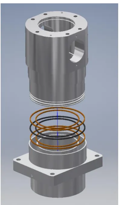
[image:45.595.199.398.401.740.2]4.1 Components
38 The construction of a pneumatic cylinder or actuator is fairly simple. The basic components of a cylinder are the cylinder structure, seals, the piston, the rod connected to the piston, base cap and bearing cap. It should be noted that this construction refers to double-acting cylinders.
4.1.1 Actuator Base
This component contains the ‘air chamber’, which changes volume as the piston moves up or down. It primarily consists of a bore which houses the bearings and seals as well as the base of the piston. The physical details have been illustrated. For actual measurements of the diameters based on these tolerances, refer to the dimension tables from section 4.1.3 on Guide Rings as well as the technical drawings in Appendix N. General tolerances have also been applied from O-ring standard tolerances from the Parker Hannifin handbook.
In general, a bore surface, which interchanges definition based on whether it is for a rod gland or piston gland, has a tolerance of H9. Bore surface is always based on the actuator base side. Machining tolerances have been applied to the guide ring groove seats. For the piston surface the tolerance grade is f7. Tolerance grade for the O-ring groove seat is h8.
4.1.2 Actuator piston
This is the moving component which ultimately transfers load to the C-ring, forming the combustion chamber seal. The area of the base dictated the pressure and therefore the load transmitted through to the metal C-ring. This was analysed based on the basic principles of pressure and its dependence on area. The motion and dynamics of the piston were analysed using MATLAB codes which computed the pressure derivative.
4.1.3 Guide Rings
39 The next stage was to determine force distributions on the guide strip.
Bertetto, Mazza and Orrú (2015) mention in their article about guide bearings that the main operating parameters for pneumatic cylinders and actuators are working pressure, actuation velocity, external load and lubrication conditions. When reviewing the literature, a paper was found (Gamez-Montero et al., 2009) that provides an analytical approach for determining load capacity of a cylinder based on misalignment effects. It was decided that this approach could very well be applied to the actuator design. Before the analytical method was applied, however, data on available guide ring sizes had to be considered first.
The ‘Fluid Power Seal Design Guide’ was consulted (Parker Hannifin 2014) to see what guide ring types and sizes were available. Two different guide ring types were identified for pneumatic applications. Either a PDT profile or PDW profile could be selected. The PDW profile offers the end user a precision machined bearing at any size that can be easily installed. The PDT profile has a rectangular cross-section, whilst the PDW profile has a trapezoidal section, with the two internal corners of the bearing being chamfered slightly. The PDW profile is the bearing profile of choice for this design.
Standard material options for this bearing are a 40% Bronze-filled PTFE and a 23% Carbon-, 2% Graphite-filled PTFE material. The Bronze-filled PTFE bearing provides better mechanical properties compared to the Carbon- and Graphite-filled bearing. Initially, this was thought to be a good choice of material due to its superiority compared to the Graphite-Carbon filled material. However, when reviewing the literature, it was realised that this material should not be used in applications where the bearing is exposed to oxidising agents (Quadrant Engineering Plastic Products, 2014). Air is considered to be an oxidising agent due to the fact that it comprises significantly of Oxygen. This can lead to tarnishing of the Bronze-filled PTFE bearing. Thus a new decision was made to instead choose the Parker 23% Carbon-, 2% Graphite-filled PTFE material, which still exhibits very desirable mechanical properties such as good yield strength.
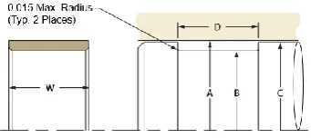
40 are for calculating custom, rod wear ring groove dimensions, from Appendix C of Parker Catalogue 5370 (Parker Hannifin 2014). This profile has the style ‘E’ (0.093” thickness).
𝑀𝑖𝑛. 𝐺𝑟𝑜𝑜𝑣𝑒 𝑑𝑖𝑎𝑚𝑒𝑡𝑒𝑟, 𝐵1
= [(𝑀𝑎𝑥𝑖𝑚𝑢𝑚 𝑟𝑜𝑑 𝑑𝑖𝑎𝑚𝑒𝑡𝑒𝑟, 𝐴1 ) + .001"] + 2 × (𝑀𝑎𝑥. 𝑐𝑟𝑜𝑠𝑠 𝑠𝑒𝑐𝑡𝑖𝑜𝑛)
(𝑀𝑎𝑥. 𝑔𝑟𝑜𝑜𝑣𝑒 𝑑𝑖𝑎𝑚𝑒𝑡𝑒𝑟) = 𝐵1 + (𝑀𝑎𝑐ℎ𝑖𝑛𝑖𝑛𝑔 𝑡𝑜𝑙𝑒𝑟𝑎𝑛𝑐𝑒𝑠)
𝑀𝑖𝑛. 𝑡ℎ𝑟𝑜𝑎𝑡 𝑑𝑖𝑎𝑚𝑒𝑡𝑒𝑟 𝐶1 = (𝑀𝑎𝑥 𝑔𝑟𝑜𝑜𝑣𝑒
𝑑𝑖𝑎𝑚𝑒𝑡𝑒𝑟 ) − 2 × (𝑀𝑖𝑛. 𝑐𝑟𝑜𝑠𝑠𝑠𝑒𝑐𝑡𝑖𝑜𝑛 ) +2 × (𝐷𝑒𝑠𝑖𝑟𝑒𝑑 𝑚𝑖𝑛. 𝑟𝑎𝑑𝑖𝑎𝑙 𝑚𝑒𝑡𝑎𝑙 − 𝑡𝑜 − 𝑚𝑒𝑡𝑎𝑙 𝑐𝑙𝑒𝑎𝑟𝑎𝑛𝑐𝑒)
[image:48.595.217.379.352.434.2]𝐷 = (𝑁𝑜𝑚𝑖𝑛𝑎𝑙 𝑤𝑖𝑑𝑡ℎ, 𝑊) + (.010")
Figure 24 – Rod gland (Parker Hannifin)
The above values are in imperial units. These were converted to metric units for calculations. The nominal measurement for bore diameter was based on O-ring selection. As this measurement did not match exactly to any of the standard wear ring gland dimensions, a custom gland design, as detailed above, was chosen. A machining tolerance of ±0.075 mm was assumed for the wear ring groove. This is a typical tolerance achievable by turning for diameters greater than 50 mm (Groover). The nominal inner bore diameter is 108 mm, meaning that the above values were worked out as follows.
Rod/inner glands:
41
𝑀𝑖𝑛. 𝑡ℎ𝑟𝑜𝑎𝑡 𝑑𝑖𝑎𝑚𝑒𝑡𝑒𝑟 𝐶1
= (112.7888) − 2 × (2.2606) + 2 × (0.005 × 25.4) = 108.5216
𝐷 = (𝑁𝑜𝑚𝑖𝑛𝑎𝑙 𝑤𝑖𝑑𝑡ℎ, 𝑊) + (.010")
To find nominal width:
𝑊 = 5𝐹
∅𝐷 × 𝑞× 𝐹𝑆
FS=3
𝑊 = 5 × 16 𝑁
0.108 𝑚 × 24.821 × 106𝑃𝑎× 3 ≈ .00009 𝑚
This is equal to about .09 mm. Practically this would be too small to handle by hand. So a width of 2.5 mm was chosen, which would provide the necessary compressive capacity and be easier to handle by hand. Therefore D was determined based on the above equations.
𝐷 = (2.5) + (. 010 × 25.4) = 2.754 𝑚𝑚
[image:49.595.210.381.445.521.2]For piston glands:
Figure 25 – piston gland (Parker Hannifin)
𝑀𝑎𝑥. 𝐺𝑟𝑜𝑜𝑣𝑒 𝑑𝑖𝑎𝑚𝑒𝑡𝑒𝑟, 𝐵
= [(𝑀𝑖𝑛𝑖𝑚𝑢𝑚 𝑏𝑜𝑟𝑒 𝑑𝑖𝑎𝑚𝑒𝑡𝑒𝑟, 𝐴 ) − .001"] − 2 × (𝑀𝑎𝑥. 𝑐𝑟𝑜𝑠𝑠 𝑠𝑒𝑐𝑡𝑖𝑜𝑛) = [142 − 0.001 × 25.4] − 2 × (.093 × 25.4) = 137.2502 𝑚𝑚
42
𝑀𝑎𝑥. 𝑝𝑖𝑠𝑡𝑜𝑛 𝑑𝑖𝑎𝑚𝑒𝑡𝑒𝑟 𝐶 = (𝑀𝑖𝑛 𝑔𝑟𝑜𝑜𝑣𝑒
𝑑𝑖𝑎𝑚𝑒𝑡𝑒𝑟 ) + 2 × (𝑀𝑖𝑛. 𝑐𝑟𝑜𝑠𝑠𝑠𝑒𝑐𝑡𝑖𝑜𝑛 ) − 2
× (𝐷𝑒𝑠𝑖𝑟𝑒𝑑 𝑚𝑖𝑛. 𝑟𝑎𝑑𝑖𝑎𝑙 𝑚𝑒𝑡𝑎𝑙 − 𝑡𝑜 − 𝑚𝑒𝑡𝑎𝑙 𝑐𝑙𝑒𝑎𝑟𝑎𝑛𝑐𝑒) = (137.1752) + 2 × (2.2606) − 2 × (. 005 × 25.4) = 141.4424 𝑚𝑚
Min piston diameter (f7) = 141.4424 mm - 0.083 mm = 141.3594 mm
𝐷 = (𝑁𝑜𝑚𝑖𝑛𝑎𝑙 𝑤𝑖𝑑𝑡ℎ, 𝑊) + (.010") = (2.5) + 0.01 × 25.4 = 2.754 𝑚𝑚
Consider the case where clearance is as large as possible. This will lead to the largest possible misalignment of the plunger-piston inside the cylinder. Contrarily, the clearance gap is smallest when components are machined as close as possible relative to each other. To give an overview of the largest and smallest clearances for both inner and outer guide rings, the following tables have been produced.
Table 1 – Largest possible clearance between outer bearing and bore Measurements (mm) Smallest groove diameter 137.1752
Smallest bearing cross-section
2.2606
Largest bore diameter (H8) 142.063 Clearance between bearing
and bore
142.063/2-(2.2606+137.1752/2)=0.1833
Now for the inner bearing and bore:
Table 2 – Largest possible clearance between inner bearing and bore Measurements (mm)
Largest groove diameter 112.7888 Smallest bearing
cross-section
2.2606
Smallest bore diameter (f7) 107.929 Clearance between bearing
and bore
43 Now for the smallest possible clearance between the outer bearing and bore:
Table 3 – Smallest possible clearance between outer bearing and bore Measurements (mm) Largest groove diameter 137.2502
Largest bearing cross-section
2.3622
Smallest bore diameter (H8) 142.0 Clearance between bearing
and bore
142/2-(2.3622+137.2502/2)=0.0127
Table 4 – Smallest possible clearance between inner bearing and bore Measurements (mm) smallest groove diameter 112.7138
largest bearing cross-section 2.3622 largest bore diameter (f7) 107.964 Clearance between bearing
and bore
112.7138/2-(2.3622)-107.964/2=0.0127
4.1.3.1 Geometric Analysis
Using the iProperties Tools in Inventor Professional 2016, the centre of Gravity could be located in a fast and simple manner. Individual masses of the assembled components were also found using the iProperties Tools. The overall mass of the upper cylinder assembly is reported here.
Overall upper cylinder assembly mass: 10.6546 kg
44 Figure 26 – Inner bearing geometry and nomenclature
[image:52.595.141.457.310.738.2]45
𝑍 = √𝐻2+ 𝑊2
cos ∅1=𝑊
𝑍
cos ∅2=𝑊+2×𝐶
𝑍 (outer bearings)
cos ∅2=𝑊−2×𝐶𝑍 (inner bearings)
Outer bearings, smallest gap:
Largest groove diameter = 137.2502 mm Largest bearing C.S. = 2.3622 mm
𝑊 = 137.2502 + 2.3622 × 2 = 141.9746 𝑚𝑚 H = 14.508 mm
C = 0.0127 mm
𝑍 = √14.5082+ 141.97462≈ 142.7139 𝑚𝑚
𝑊 + 2𝐶 = 141.9746 + 2 × 0.0127 = 142 𝑚𝑚 ∅1= cos−1(141.9746
142.7139) ≈ 5.83448∘
∅2= cos−1( 142
142.7139) ≈ 5.7333∘ 𝜃 = ∅1− ∅2= 5.8345 − 5.7333 = 0.1012°
Inner bearings, smallest gap:
smallest groove diameter = 112.7498 mm largest bearing C.S. = 2.3622 mm
𝑊 = 112.7498 − 2.3622 × 2 = 108.0254 𝑚𝑚 H = 14.508 mm
C = 0.0127 mm
𝑍 = √14.5082+ 108.02542≈ 108.9953 𝑚𝑚
𝑊 − 2𝐶 = 108.0254 − 2 × 0.0127 = 108 𝑚𝑚 ∅1= cos−1(108.0254
108.9953) ≈ 7.64927∘ ∅2= cos−1(
108
108.9953) ≈ 7.7489∘ 𝜃 = ∅2− ∅1 = 0.0986°
Outer bearings, largest gap:
46 smallest bearing C.S. = 2.2606 mm
𝑊 = 137.1752 + 2.2606 × 2 = 141.6964 𝑚𝑚 H = 14.508 mm
C = 0.1833 mm
𝑍 = √14.5082+ 141.69642≈ 142.43719 𝑚𝑚
𝑊 + 2𝐶 = 141.6964 + 2 × 0.1833 = 142.063 𝑚𝑚 ∅1= cos−1(
141.6964
142.43719) ≈ 5.846∘
∅2= cos−1( 142.063
142.43719) ≈ 4.15401∘ 𝜃 = ∅1− ∅2= 5.846 − 4.15401 = 1.692°
Inner bearings, largest gap:
Largest groove diameter = 112.7888 mm smallest bearing C.S. = 2.2606 mm
𝑊 = 112.7888 − 2.2606 × 2 = 108.2676 𝑚𝑚 H = 14.508 mm
C = 0.1693 mm
𝑍 = √14.5082+ 108.26762≈ 109.2353 𝑚𝑚
𝑊 − 2𝐶 = 108.2676 − 2 × 0.1693 = 107.929 𝑚𝑚 ∅1= cos−1(
108.2676
109.2353) ≈ 7.63216∘
∅2= cos−1(107.929
109.2353) ≈ 8.8697∘ 𝜃 = ∅2− ∅1 = 1.2375°
4.1.3.2 Stress Analysis
47 Ren and Muschta (2010) provided a model for edge loading of polymer bearings. The model requires a guessed deflection of the bearing at the loaded edge, followed by an iterative process. Below is the nomenclature that describes the equations to follow.
Fcapacity = 𝐾𝜇∙ 𝐾𝜂 𝐸𝑐𝐷𝛿𝑚2
𝑊𝑆 supporting force of bearing (N)
𝐾𝜇 = (1 − 𝜇)/(1 + 𝜇)(1 − 2𝜇)
The above value is a factor based on the assumption that two strains other than loading direction are zero. This assumption could lead to a stiffer bearing and higher estimated edge load than the actual one (Ren and Muschta, 2010). The factor below was obtained by integrating bearing pressure over the actual contact area and is valid only if the length of the contact area is smaller than the bearing length (Ren and Muschta, 2010).
Kη = 0.0959η3 – 0.086η2 + 0.327η – 0.0017
μ = Poisson ratio
Ec = Compressive E-modulus of bearing material
Unfortunately no data could be found that specifically gave the strain for 23% Carbon-, 2% Graphite-filled PTFE under compression. Thus data was taken from experimentation done on the compression of standard PTFE. For a temperature of 26˚C, the measured strain for the PTFE with a true stress of 25 MPa was approximately 0.25. The Parker tables for this material do indicate the compressive strength (in psi). Therefore this compressive strength, combined with the approximate strain of standard PTFE, would give a rough estimate of the compressive modulus of 23% Carbon-, 2% Graphite-filled PTFE. The estimated value for Ec is reported below.
Ec = 24.8211/0.025 MPa ≈ 992.844 MPa
D = Shaft diameter (mm)
W = Wall thickness of bearing (mm) S = shaft slope at bearing
δm = max. deflection of bearing surface at edge of bearing end (mm)
𝜂 = sin (𝛷𝑚
2 ) = √1 − [
(1 + Ψ)2+ (2𝛿𝑚
𝐷 + Ψ)
2
− 1 2(1 + Ψ) (2𝛿𝑚
𝐷 + Ψ) ]
2