This is a repository copy of Combating automative engine valve recession . White Rose Research Online URL for this paper:
http://eprints.whiterose.ac.uk/778/
Article:
Lewis, R. and Dwyer-Joyce, R.S. (2003) Combating automative engine valve recession. Tribology and Lubrication Technology, 59 (10). pp. 48-51. ISSN 0024-7154
[email protected] https://eprints.whiterose.ac.uk/ Reuse
Unless indicated otherwise, fulltext items are protected by copyright with all rights reserved. The copyright exception in section 29 of the Copyright, Designs and Patents Act 1988 allows the making of a single copy solely for the purpose of non-commercial research or private study within the limits of fair dealing. The publisher or other rights-holder may allow further reproduction and re-use of this version - refer to the White Rose Research Online record for this item. Where records identify the publisher as the copyright holder, users can verify any specific terms of use on the publisher’s website.
Takedown
If you consider content in White Rose Research Online to be in breach of UK law, please notify us by
White Rose Consortium ePrints Repository
http://eprints.whiterose.ac.uk/
This is an author produced version of a paper published in Tribology and Lubrication
Technology. This paper has been peer-reviewed but may not include the final
publisher proof-corrections or journal pagination.
White Rose Repository URL for this paper: http://eprints.whiterose.ac.uk/archive/00000778/
Citation for the published paper
Lewis, R. and Dwyer-Joyce, R.S. (2003) Combating automative engine valve
recession: a case study. Tribology and Lubrication Technology, 59 (10). pp. 48-51.
Citation for this paper
To refer to the repository paper, the following format may be used:
Lewis, R. and Dwyer-Joyce, R.S. (2003) Combating automative engine valve
recession: a case study. Author manuscript available at:
http://eprints.whiterose.ac.uk/archive/00000778/ [Accessed: date].
Published in final edited form as:
Lewis, R. and Dwyer-Joyce, R.S. (2003) Combating automative engine valve
recession: a case study. Tribology and Lubrication Technology, 59 (10). pp. 48-51.
COMBATING AUTOMOTIVE ENGINE VALVE RECESSION: A CASE
STUDY
R. Lewis* and R.S. Dwyer-Joyce
Department of Mechanical Engineering, The University of Sheffield, Mappin Street, Sheffield, S1 3JD, UK.
corresponding author: tel: +44 (0) 114 2227838, fax: +44 (0) 114 2227890, [email protected], www.tribologyatsheffield.com
INTRODUCTION
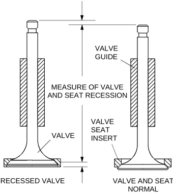
Valve recession occurs when wear of the valve or seat inserts in an automotive engine has caused the valve to sink or recede into the seat insert (as shown in Figure 1).
Excessive recession leads to valves not seating correctly and cylinder pressure loss. Leaking hot combustion gases can also cause valve guttering or torching, which will accelerate valve failure.
MEASURE OF VALVE AND SEAT RECESSION
RECESSED VALVE VALVE AND SEAT NORMAL VALVE
GUIDE
VALVE
[image:3.595.212.382.340.529.2]VALVE SEAT INSERT
Figure 1. Valve Recession
Although new valve materials and production techniques are constantly being developed, these advances have been outpaced by demands for increased engine performance and wear related problems remain an issue. Dynamometer engine testing is often used to establish short-term solutions. This is time consuming and does not necessarily reveal the actual causes of wear.
THE PROBLEM
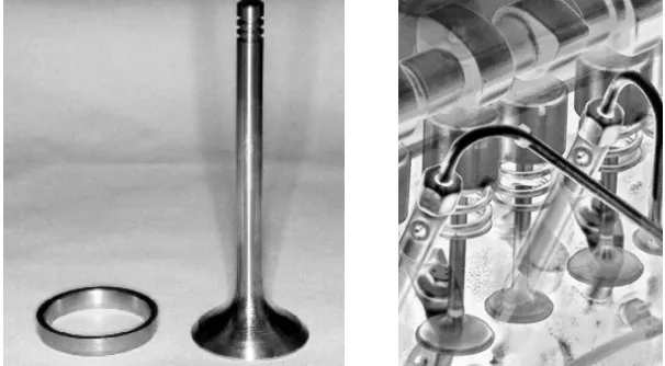
[image:4.595.146.449.214.381.2]The failures that initiated the investigation involved an eight valve, 1.8 litre, direct injection diesel engine, with direct acting cams. The engine was undergoing design upgrades, one of which was the change from indirect to direct injection. The meant the inclusion of holes in the cylinder-head between the inlet and exhaust ports to accept the fuel injector. A new seat insert material was also being trialed in the tests. The material had solid lubricants incorporated, which were thought to help improve machinability and reduce sliding wear problems at the valve/seat interface. The valve, seat insert and operating system are shown in Figure 2.
Figure 2. Valve, Seat Insert and Valve Operating System
A number of problems occurred during pre-production dyno-testing. The new seat insert material exhibited excessive wear (0.3mm of recession in 100 hours). Further analysis also revealed that uneven wear of the seat inserts was occurring. This was found to be a result of by thermal distortion of the seat inserts thought to be due to enforced changes in cooling channels to incorporate the fuel injectors. On cooling the seat inserts returned to their original shape, which meant on restarting the valves were unable to seat properly and cylinder pressure loss resulted.
LABORATORY INVESTIGATIONS
Test Apparatus
Laboratory component test-rigs (hydraulic loading apparatus and a motorised cylinder-head) were developed to provide a simulation of the contact between valves and seats [1, 2]. These were used to investigate the fundamental wear mechanisms and the effect of critical engine operating parameters.
The hydraulic loading apparatus was used to simulate both combustion loading and impact on valve closure. Test methodologies developed have isolated the effects of impact and sliding. The motorised cylinder-head was used to investigate the impact wear caused during valve closing.
Wear Mechanisms
involves two distinct mechanisms:
• Impact as the valve strikes the seat on closure.
• Micro-sliding at the valve/seat interface caused by elastic deformation of the valve head as it is pressed into the seat by the combustion pressure.
[image:5.595.75.522.260.361.2]Impact on valve closure causes plastic deformation of the seating face surface and the formation of a series of circumferential ridges and valleys. It also led to surface cracking and subsequent material loss from seat inserts at high closing velocities. Sliding caused the formation of radial scratches on the seat insert seating faces.
Figure 3 illustrates some of these features and compares wear surfaces on valves and seats run in the test apparatus (Figure 3a and b) with those examined during failure analysis of valves and seats from engine tests (Figure 3c and d).
Figure 3. Laboratory Tested Valve (a) and Seat Insert (b) Compared with Engine Tested Valve (c) and Seat Insert (d)
Effect of Engine Operating Parameters
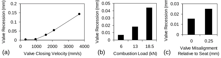
The test work showed that recession was strongly dependent on valve closing velocity, combustion load and valve/seat insert misalignment, as shown in Figure 4 [3].
0 0.05 0.1 0.15 0.2
0 1000 2000 3000 4000 Valve Closing Velocity (mm/s)
V a lv e R e ce ssi o n ( m m ) 0 0.01 0.02 0.03 0.04 0.05
6 13 18.5 Combustion Load (kN)
V al ve R ec es s ion ( m m ) 0 0.01 0.02 0.03 0 0.25 Valve Misalignment Relative to Seat (mm)
[image:5.595.82.516.482.597.2]V a lv e R e ce ssi o n ( m m )
Figure 4. Valve Recession with Cast Tool Steel Seat Inserts for Increasing (a) Valve Closing Velocity (after 100 000 cycles); (b) Combustion Load (after 25000 cycles) and (c) Valve
Misalignment (after 25000 cycles)
DEVELOPMENT OF PREDICTIVE MODELS
A valve recession prediction model has been developed using the results of the bench testing [3]. The model considers impact and sliding separately as they occur as two separate load events. Parameters were derived either directly from the valve and seat design and engine operating conditions or from bench test results. The model has the form:
(a)
(b)
(c)
(d)
j i n A A mv KN H N P k V ⎟ ⎠ ⎞ ⎜ ⎝ ⎛ ⎟ ⎟ ⎠ ⎞ ⎜ ⎜ ⎝ ⎛ ⎟ ⎠ ⎞ ⎜ ⎝ ⎛ + = 2 2 1
δ
(1)where V is the wear volume, P is the average load at the valve/seat interface, N is the number of cycles, δ is the slip at the valve/seat interface, H is the seat hardness, k is a sliding wear coefficient determined during wear tests, m is the mass of valve and follower and v is the valve closing velocity and K and n are impact wear constants determined during wear testing.
The factor, consisting of the ratio of the initial valve/seat contact area, Ai, to the contact area
after N cycles, A, to the power of a constant j, was included in order to incorporate the change in pressure at the interface and other effects likely cause a reduction in the wear rate with time, such as work hardening. The constant j was determined empirically using bench and engine test data.
The wear volume can readily be converted into a linear recession from the seat geometry
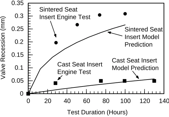
To provide a tool for running the wear modelling code software called RECESS has been developed. Figure 5 shows RECESS predictions against measured data for engine dyno-tests run using cast and sintered tool steel inserts. As can be seen, the model produces a good prediction of valve recession.
0 20 40 60 80 100 120 140
Test Duration (Hours) 0 0.05 0.1 0.15 0.2 0.25 0.3 0.35 V a lv e R e c e s s io n ( m m ) Sintered Seat Insert Model Prediction Sintered Seat
Insert Engine Test
Cast Seat Insert Engine Test
[image:6.595.165.434.359.545.2]Cast Seat Insert Model Prediction
Figure 5. Model Predictions versus Engine Test Data
IDENTIFY FAILURE Excessive Valve Wear Valve Fatigue Failure Excessive Seat Wear Uneven Seat Wear
Due to Impact
Due to Sliding Due to Guttering
Due to Impact
Due to Sliding
Material not Suitable
Valve Closing Velocity too High
Poor Valve Design Seating Angle too High Head Stiffness too Low Flaking of Deposit/Varnish
(formed from lubricant)
Valve Misalignment Relative to Seat
Incorrect Fit on Seat Insert Causing High Hoop Stresses Thermal Softening Due to Excessive Temperature
Seat Area not Hardened Adequately
Inadequate/Non-Uniform Cooling
Deposit Build-Up Reducing Heat Transfer
Poor Manufacturing Tolerances Hardness too Low
Fracture Toughness too Low
Poor Cam Design
Clearance too High
Dynamic Problem with Camshaft
Redesign Valve Head Redesign Cam Profile
Reduce Clearance Use Wear Resistant Coating on Seating Face
Redesign Head Cooling Channels
Check/Improve Induction Hardening Process
Improve Tolerances on Head Machining Select New Material
Reduce Lubricant Supply to Valve/Seat Interface SOLVING THE PROBLEM ANALYSING THE PROBLEM
What Has Happened? What Caused it to Happen?
[image:7.595.73.524.69.374.2]Reduce Interference Fit on Seat Insert Investigate Camshaft Dynamics and Correct Any Problems FAILURE
Figure 6. Solving Valve/Seat Failure Problems
ADOPTED SOLUTION
The short term solution for the recession problem outlined was to replace the seat insert material with a material exhibiting higher toughness to reduce the effect of impact wear on valve closure. The structure of the original material meant it had good resistance to sliding wear, but low fracture toughness. The impact issue was also addressed by altering the inlet cam profile slightly to reduce the valve closing velocity.
The problem of uneven wear caused by thermal distortion of the seat inserts was remedied by reconfiguring the cylinder-head cooling channels to promote uniform cooling around the seat inserts.
A new long-term approach to combating valve recession is now possible. As new engine design changes are made, the prototype valve train systems are typically modelled in multi-body simulation packages. The output from these (loads and deformations) are used as inputs to RECESS to predict recession rates for a given design. In this way it may be possible to design out the causes of valve recession.
REFERENCES
[1] Lewis, R., Dwyer-Joyce, R.S., Josey, G., 2000, "Design and Development of a Bench Test-Rig for Investigating Diesel Engine Inlet Valve and Seat Wear", Transactions of Mechanical Engineering - IEAust, Vol. 24, No. 1, pp39-46.