UNIVERSITI TEKNIKAL MALAYSIA MELAKA
STUDY OF SPEED CONTROL FOR AN ELECTRIC
BICYCLE BASED ON PID CONTROL ALGORITHM
This report submitted in accordance with requirement of the Universiti Teknikal Malaysia Melaka (UTeM) for The Bachelor of Electronics Engineering
Technology (Industrial Electronic) with Honours
By
MOHD NABIL FIKRI BIN ROSLI B071310136
901215-07-5295
UNIVERSITI TEKNIKAL MALAYSIA MELAKA
BORANG PENGESAHAN STATUS LAPORAN PROJEK SARJANA MUDA
TAJUK: Study Of Speed Control for an Electric Bicycle Based on PID Control Algorithm
SESI PENGAJIAN: 2016/17 Semester 1
Saya MOHD NABIL FIKRI BIN ROSLI
mengaku membenarkan Laporan PSM ini disimpan di Perpustakaan Universiti Teknikal Malaysia Melaka (UTeM) dengan syarat-syarat kegunaan seperti berikut:
1. Laporan PSM adalah hak milik Universiti Teknikal Malaysia Melaka dan penulis. 2. Perpustakaan Universiti Teknikal Malaysia Melaka dibenarkan membuat salinan
untuk tujuan pengajian sahaja dengan izin penulis.
3. Perpustakaan dibenarkan membuat salinan laporan PSM ini sebagai bahan pertukaran antara institusi pengajian tinggi.
4. **Sila tandakan ( )
SULIT
TERHAD
TIDAK TERHAD
(Mengandungi maklumat yang berdarjah keselamatan atau kepentingan Malaysia sebagaimana yang termaktub dalam AKTA RAHSIA RASMI 1972)
(Mengandungi maklumat TERHAD yang telah ditentukan oleh organisasi/badan di mana penyelidikan dijalankan)
** Jika Laporan PSM ini SULIT atau TERHAD, sila lampirkan surat daripada pihak berkuasa/organisasi berkenaan dengan menyatakan sekali sebab dan tempoh laporan PSM ini perlu dikelaskan sebagai SULIT atau TERHAD.
Disahkan oleh:
Cop Rasmi:
Tarikh: _______________________ Alamat Tetap:
Lot 2123-13 kampung Changkat,
Batu 6 ¾ Gombak,
53100 Kuala Lumpur Selangor.
i
DECLARATION
I hereby, declared this report entitled “ Study Of Speed Control For An Electric Bicycle Based On PID Algorithm” is the results of my own research except as
cited in references.
Signature:
Name: MOHD NABIL FIKRI BIN ROSLI
ii
APPROVAL
This report is submitted to the Faculty of Engineering Technology of UTeM as a partial fulfillment of the requirements for The Degree of Bachelor of Electronics Engineering Technology (Industrial Electronics) with Honours. The member of the
supervisory is as follow:
iii
ABSTRAK
iv
ABSTRACT
v
DEDICATIONS
vi
ACKNOWLEDGMENTS
vii
TABLE OF CONTENTS
CHAPTER 1 1
1.0 Background 1
1.1 Problem Statement 2
1.2 Objectives 2
1.3 Project Scope 2
1.4 Project Report Outline 3
CHAPTER 2 4
2.0 Introduction 4
2.1 Introduction controlling DC motor based on PID Algorithm 4
2.2 PID Controller 5
2.2.1 PID controller to produce stability system 6
2.3 DC Geared motor 8
2.3.1 Motor Technical specification 9
2.3.2 DC motor Modelling 9
2.4 Motor Driver 11
2.5 LCD Display 20x4 14
2.6 Potentiometer 15
2.7 Rotary encoder 15
2.7.1 Encoder circuit connection 17
2.7.2 Two Channel Encoder Connection 17
2.8 Arduino Microcontroller 18
2.8.1 Arduino Uno 19
viii
2.10 Previous Work on Modelling a PID controller for DC motor 21
2.10.1 A Modified Design of PID Controller for DC Motor Drives Using
Particle Swarm Optimization PSO 21
2.10.2 PID Voltage Control for DC Motor Using MATLAB Simulink and Arduino
Microcontroller 22
2.10.3 Speed Control of DC Motor using Pid Controller Based on Matlab 23
2.10.4 Speed Control of DC Motor Using Genetic Algorithm Based PID
Controller 23
2.11 Summary 24
CHAPTER 3 25
3.0 Introduction 25
3.1 Project Planning 27
3.2 Project Flow 27
3.2.1 Information Gathering 29
3.3 Testing and Troubleshooting 29
3.4 Conceptual Design 29
3.5 Software and Programming 30
3.5.1 Proteus Software 30
3.5.2 GUI using VISUAL BASIC 33
3.5.2.1 DC Motor Modelling 34
3.5.2.2Transfer Function for procedure for determining component values 35
3.5.2.3 Parameter Obtain Ra 36
3.5.2.4 Parameter Obtain La 36
3.5.2.5 Parameter Obtain K 37
ix
3.6 Hardware Development 38
3.6.1 Hardware prototype design for Electric Bicycle using Arduino UNO 39
3.6.2 Arduino UART to USB connection 39
3.6.3 Arduino Power Supply 40
3.6.4 LCD connection to Arduino 41
CHAPTER 4 42
4.0 Introduction 42
4.1 Project Prototype 42
4.2 Hardware Development and Experimental Works 42
4.3 Software Development and Experimental Works 43
4.3.1 Arduino Programming 44
4.3.2 GUI interface using Visual Basic 46
4.4 Experimental result 47
4.4.1 Open loop system analysis 47
4.4.1.1 Load Disturbance Open-loop system Analysis Data 48
4.4.2 Closed loop system analysis (Static setpoint) using PID controller 50
4.4.2.1 Load Disturbance PID closed loop system Analysis Data 56
4.4.3 Dynamic setpoint Analysis 58
4.5 Overall system Flow 60
4.5.1 Display to Serial Monitor Arduino 60
4.5.2 Display in LCD 61
4.5.3 Transfer data to Excel 62
x
CHAPTER 5 64
5.0 Introduction 64
5.1 Research of summary 64
5.2 Achievement of Research Objective 65
5.3 Significance of Research 65
5.4 Recommendation 66
5.5 Project Potential 66
xi
LIST OF FIGURES
2.1 Block diagram of Closed loop system 5
2.2 Block diagram of PID controller system 6
2.3 Example Step response graph representing steady-state error , rising time
overshootand setling time 7
2.4 Planetary DC Geared Motor (42mm) 14:1 8
2.5 Equivalent circuit for DC motor 9
2.6 DC motor armature control system block diagram 10
2.7 10 Amp Dc motor driver MD 10C 11
2.8 Operation of H Bridge Circuit 13
2.9 LCD Display 20x4 14
2.10 Example connection of LCD display connect with Arduino 14
2.11 Potentiometer 10K 15
2.12 Rotary encoder 15
2.13 Two output from rotary encoder represent two square wave in
Quadrature 16
2.14 Arduino circuit connection for encoder 17
2.15 Example of Arduino Board 18
2.16 Basic layout of Arduino UNO microcontroller 19
3.1 Planning of speed control for an electric bicycle based on PID control
algorithm Phase 25
3.2 Step of Methodology 26
xii
3.4 Illustration design for the system 30
3.5 Interface feature in Proteus Software 31
3.6 Arduino UNO connection pin in Proteus 31
3.7 Motor Circuit connection pin in Proteus 32
3.8 Analog Input/Potentiometer Circuit connection pin in Proteus 32
3.9 Digital Input/Push Button Circuit connection pin in Proteus (prototype) 32
3.10 Display Circuit connection pin in Proteus 33
3.11 GUI interface using Visual Basic 34
3.12 DC motor modelling schematic 34
3.13 Arduino Interface Software 38
3.14 Prototype of design for Electrical bicycle using Arduino 39
3.15 Connection UART to USB using Arduino 39
3.16 Arduino UNO supply 40
3.17 LCD connection to Arduino UNO 41
4.1 Connectivity of Arduino UNO, DC motor, LCD display and rotary
Encoder 43
4.2 Code PID tuning value 44
4.3 Code of declaration of RPM, PID value and LCD display 45
4.4 Visual Basic For Prototype of an electric bicycle 46
4.5 Controlling the speed of DC motor using Potentiometer (PWM) 47
4.6 Controlling the speed of DC motor in Percentage 47
4.7 Controlling PWM value and The Output value of DC motor 48
xiii
4.9 Graph for Testing Load disturbance for setpoint 150 rpm 49
4.10 Graph for Testing Load disturbance for setpoint 200 rpm 49
4.11 PID tuning Kp=0.05 , Ki=0.05 and Kd=0 50
4.12 Output value for Kp=0.05 , Ki=0.05 and Kd=0 50
4.13 PID tuning Kp=0.10 , Ki=0.05 and Kd=0 51
4.14 Output value for Kp=0.10 , Ki=0.05 and Kd=0 51
4.15 PID tuning Kp=0.010 , Ki=0.05 and Kd=0 52
4.16 Output value for Kp=0.010 , Ki=0.05 and Kd=0 52
4.17 PID tuning Kp=0.010 , Ki=0.10 and Kd=0 53
4.18 Output value for Kp=0.010 , Ki=0.10 and Kd=0 53
4.19 PID tuning Kp=0.010 , Ki=0.3 and Kd=0 54
4.20 Output value for Kp=0.010 , Ki=0.3 and Kd=0 54
4.21 PID tuning Kp=0.010 , Ki=0.3 and Kd=0.01 55 4.22 Output value for Kp=0.010 , Ki=0.3 and Kd=0 55
4.23 Load are been apply in real time application 56
4.24 Testing closed loop using load disturbance 0.25 KG 57
4.25 Testing closed loop using load disturbance 1.5 KG 57
4.26 Testing closed loop using load disturbance 2.5 KG 57
4.27 Dynamic setpoint analysis 1 using PID parameter:Kp=0.010
Ki=0.3 and Kd=0 58
4.28 The output value for parameter Kp=0.010, Ki=0.3 and Kd=0 59 4.29 Dynamic setpoint analysis 2 using PID parameter:Kp=0.010 ,
Ki=0.3 and Kd=0.01 59
4.30 The output value for parameter Kp=0.010, Ki=0.3 and Kd=0 60
4.31 Display of the Serial Monitor in Arduino 61
xiv
xv
LIST OF TABLES
2.1 DC geared motor technical specification 9
2.2 Absolute Power Maximum for Motor Driver MD 10C 12
2.3 Connection motor and power Source 12
2.4 Motor Encoder technical specification 17
2.5 Arduino UNO Technical Specification 20
3.1 Description of state variable based on equivalent motor transfer function 35
4.1 Summarize of experiment take out to find optimum parameter for PID
controller 56
xvi
LIST OF SYMBOLS AND ABBREVIATIONS
DC motor = Direct Current motor
PID = Propotional Integral
Derivative
Tr = Time rising
Ts = Time Setling
%sse = Steady state error
Kp = Propotional Gain
Ki = Intergral Gain
1
CHAPTER 1
INTRODUCTION
1.0 Background
2 1.1 Problem Statement
1. Trishaw riders carry a heavy customer to generate their income to help their family.
2. Trishaw riders have to climb up the slope and hilly to reach the destination that been deal with passenger.
3. Trishaw rider exhausted to cycle the Trishaw.
1.2 Objectives
1. To design a closed-loop system for DC motor that be controlled using PID to easy the trishaw rider for carry heavy load.
2. To create a PID controller for the purpose of controlling the speed of DC motor. 3. To create a hardware for the DC motor with input paddle for real implement. 4. To reduce air pollution and create green technology product.
1.3 Project Scope
This project is done on Hardware and Software. The software that been used is Arduino UNO. It delivers 14 digital input and output pins. It either be use as PWM output. The parameter of the PID can be tune using Matlab/Simulink or manual adjusting in prototype, The Parameter will be program by using Arduino language. The Arduino is use to drive the speed of DC motor. The Arduino is the easy program to control the plant that we want. The Hardware that use is a DC motor. The DC motor is controlled by using Arduino UNO. The input on this project is a Paddle reading by rotary encoder. The Paddle will oscillate by the rider to trigger the DC motor. The rider only has to paddle only a certain RPM. The amount RPM that we set will be the speed of the DC motor.
3
display using Zed graph plot in visual basic to display Real time setpoint and Actual speed for the system. The value for setpoint and actual speed is also display in the GUI.
1.4 Project Report Outline
4
CHAPTER 2
LITERATURE REVIEW
2.0 Introduction
In this segment it will talk about the literature, talk and see of past examination and some meaning of the parts utilized as a part of this project for example, Arduino microcontroller, DC motor demonstrating and other. Through the world, there have various diverse sources and investigates about the idea, plan and usage of the Arduino to control DC motor utilizing PID control calculation. It additionally contained the examination of what others have done in this section. This review incorporated the hardware and software development. Writing audits are based on data that got from various sources, articles, specialized reports, general reports, sites, books and individual correspondence.
2.1 Introduction controlling DC motor based on PID Algorithm.
5
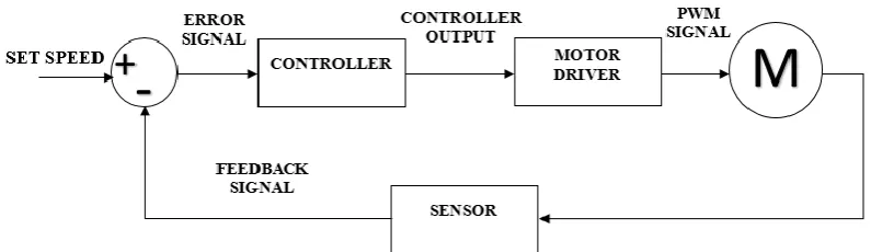
[image:23.595.117.515.141.256.2]the system through a control component, for example, the area of a control valve, or power provided to a heating component.
Figure 2.1: Block diagram of closed loop system.
In this project, we are controlling the speed of a DC motor in PID parameter utilizing Arduino UNO. This microcontroller is a best decision for this project since its simple and environment client encounter, Arduino has been utilized as a part of a large number of various activities and applications. The Arduino writing computer programs is definitely not hard to-use for novices, yet adequately versatile for bleeding edge customers. Educators and researcher similarly utilize it to make negligible exertion legitimate instruments, to show science and material science guidelines, or to initiate annoyed out with programming and mechanical innovation. Inside decorators and architects build savvy models, entertainers and pros use it for foundations and to attempt distinctive things with new melodic instruments.
2.2 PID Controller
6
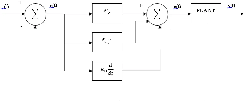
[image:24.595.116.520.247.421.2]and altering the armature voltage or potentially the field current will move the rotor speed. In the meantime PID controller has some advantage, specifically, the undesirable speed overshoot and the ease back reaction because of sudden change in load torque and the affectability to controller picks up KI and KP [6] . The operation of this shut circle controller relies on upon the exactness of framework models and parameters. Consequently there is a request of a controller which can settle shortcomings of PID controller.
Figure 2.2: Block diagram of PID controller system
2.2.1 PID controller to produce stability system
In this project, DC motor speed control is developed by the PID controller. The performance measure to be minimized contains the following objectives of the PID controller:-