Int. J. Electrochem. Sci., 7 (2012) 3420 - 3435
International Journal of
ELECTROCHEMICAL
SCIENCE
www.electrochemsci.org
Performance Analysis and Multi-Objective Optimization of a
Molten Carbonate Fuel Cell-Braysson Heat Engine Hybrid
System
Houcheng Zhang, Shanhe Su, Guoxing Lin*, and Jincan Chen
Department of Physics, Xiamen University, Xiamen 361005, People’s Republic of China *
E-mail: [email protected]
Received: 16 January 2012 / Accepted: 2 March 2012 / Published: 1 April 2012
A new hybrid system consisting of a molten carbonate fuel cell (MCFC) and a Braysson heat engine is established, in which multi-irreversibilities resulting from the overpotentials in the electrochemical reaction, heat leak from the MCFC to the environment, non-perfect regeneration in the regenerator, and finite-rate heat transfer in the Braysson heat engine are taken into account. Analytical expressions for the efficiency and power output of the hybrid system are derived through thermodynamic-electrochemical analyses, from which the general characteristics of the system are revealed and the optimum criteria of some of the main parameters such as the current density, efficiency and power output are given. The influence of the irreversible losses on the performance of the hybrid system is discussed. Moreover, a multi-objective function including both the power output and efficiency is introduced and used to further subdivide the parametric optimum regions according to different requirements which are often faced in the design and operation of practical fuel cell systems. The results obtained here are very general and may be directly used to derive the variously interesting conclusions of the hybrid system operated under different special cases.
Keywords: Molten carbonate fuel cell, Braysson heat engine, irreversibility, performance analysis, multi-objective optimization
1. INTRODUCTION
temperatures provide the possibility of cogeneration with other types of power generators such as gas turbines [11-14] or other types of heat engines [15-18], so that the performance of the MCFC can be enhanced.
The Braysson cycle is a new power cycle model proposed by Frost et al. [19, 20], which is based on a conventional Brayton cycle for the high temperature heat addition and the Carnot cycle for the low temperature heat rejection. The reversible and endoreversible performance of the Braysson cycle has been investigated and some significant results have been obtained [21-23]. When the Braysson cycle is combined with an MCFC, one can establish a novel MCFC-Braysson heat engine hybrid system for further power generation.
In the present paper, the performance of the MCFC-Braysson heat engine hybrid system will be analyzed and optimized systematically. The concrete contents are arranged as follows. In Sec. 2, the model of a hybrid system consisting of an MCFC, a regenerator, and a Braysson heat engine is established and each assembly unit in the system will be briefly described. The efficiency and power output of the hybrid system are derived. In Sec. 3, the general performance characteristics of the hybrid system are revealed through numerical calculation. A multi-objective function is introduced to further expound how to give consideration to both the efficiency and the power output of the hybrid system. In Sec. 4, the effects of the operating temperature and some synthesized parameters representing the irreversible losses on the performance of the hybrid system are discussed in details. Some significant results for several special cases are directly obtained. Finally, some important conclusions are summarized.
2. THE MODEL OF AN IRREVERSIBLE MCFC-BRAYSSON HEAT ENGINE HYBRID SYSTEM
qLoss MCFC
(T)
Regenerator
T0
PM
PH
ql
Braysson Heat Engine
reactants products
[image:2.596.171.423.476.679.2]qh
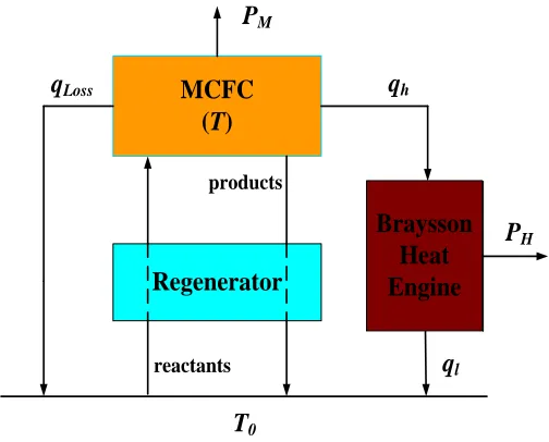
environment temperature, T is the working temperature of the MCFC, PM and PH are the power outputs of the MCFC and Braysson heat engine, qh is the rate of heat transfer between the MCFC and the Braysson heat engine, ql is the rate of heat transfer between the Braysson heat engine and the environment, qLoss is the rate of heat losses from the MCFC to the environment. In Fig. 1, the MCFC acts as the high-temperature heat reservoir of the Braysson heat engine for a further power production and the regenerator in the hybrid system is to preheat the incoming reactants by means of the heat in the high temperature products. By using such a hybrid system, the heat produced in the MCFC can be efficiently utilized, and consequently, the performance of the MCFC system can be improved.
Below, every assembly unit in the hybrid system will be, respectively, discussed in the next several subsections.
2.1 An irreversible MCFC
Many researchers have elaborately demonstrated the operating mechanism of the MCFC [1, 11, 24-27]. Here, we only give a brief description for an MCFC. As shown in Fig. 1, an MCFC is operated by introducing hydrogen to the anode and oxygen and carbon dioxide (if necessary) to the cathode, respectively. At the anode hydrogen reacts with carbonate ions available in the carbonate electrolyte into water and carbon dioxide and releases electrons to the external electric circuit, i.e.,H2 CO32 H2OCO2 2e. At the cathode oxygen reacts with carbon dioxide and electrons into carbonate ions, i.e., O2CO22e CO32
2 1
. The overall electrochemical reaction is
heat y electricit CO
O H CO
O 2 1
H2 2 2,cat 2 2,an , (1)
where subscripts “an” and “cat” indicate “ anode” and “cathode”, respectively. To sustain the total electrochemical reaction, the produced carbon dioxide is transported from the anode to the cathode while the produced carbonate ions flow from the cathode to the anode. It should be pointed out that the overall reaction is exo-energetic. These energies include an electric part, which is consumed in the external electric circuit, and a thermal part, which can be used for further power production by Braysson heat engine, i.e., H GTS , where
H
is the total energy released by the reaction,
G
is the electric part and
T
S
is the thermal part.According to Faraday’s law, hydrogen consumption rate in the electrochemical reaction is determined by = /( )
2
•
F n I
qH e , where I is the operating electric current, ne is the number of electrons,
and F is Faraday’s constant [28, 29]. Thus, the maximum possible energy (both electrical and thermal) released by the reactions is [15]
F n
h I h q H
e H
2
where
h
is the molar enthalpy change and can be calculated from the data in Refs. [28, 30-32]. It is well known that the measured open circuit voltage Ucell in a practical fuel cell is always lower than the ideal reversible voltage U0 determined by the Nernst equation [25, 33-35] because there exist some irreversible losses resulting from the anode overpotential Uan, cathode overpotentialcat
U , and ohmic overpotential Uohm. The three overpotentials can be, respectively, expressed as [24, 26, 34, 36]:
1.0 an , O H 17 . 0 an , CO 42 . 0 an , H , 9 2 2 2 exp 10 27 .
2
p p p
RT E j
Uan actan , (3)
09 . 0 cat , CO 43 . 0 cat , O , 10 2 2 exp 10 505 .
7
p p
RT E j
Ucat actcat , (4)
and 923 1 1 3016 exp 10 5 . 0 4 T j
Uohm , (5)
where j is the operating current density; R is the universal gas constant; Eact is the activation energy, and pk are the partial pressures of species k at the anode or cathode. It should be pointed out that the anode overpotential can be achieved its minimum when the anode gas inlet compositions are optimally chosen. By using numerical calculation, the concrete values of the optimal anode gas compositions under the different H2 concentrations are given in Ref. [27].
With the help of the above analysis, the efficiency and power output of an irreversible MCFC may be, respectively, expressed as
0
0
( )
e an cat ohm
M M
n F U U U U
P h H (6) and 0 ( )
M cell an cat ohm
P U I U U U U I, (7)
where
an , CO an , O H cat , CO 2 1 cat , O an , H 0 0 2 2 2 2 2 ln p p p p p F n RT E U e
, E0 g0/ (n Fe ) is the ideal standard potential,
0
242000 45.8
g T
2.2 An irreversible regenerator
The regenerator in the hybrid system acted as a heat exchanger, heating the inlet reactants from the ambient temperature to the temperature of MCFC by using the high-temperature products. When the regenerative efficiency of the regenerator is equal to 1, the regenerative process is ideal and the additional heat is unnecessary.
It should be pointed out that owing to the existence of the thermal resistance, the regenerative losses are inevitable. It is reasonable to assume that the rate of the regenerative losses is directly proportional to the temperature difference between the MCFC and the environment [38, 39], i.e.,
0
(1 )( )
re re re
q U A TT , (8)
where Ure and Are are, respectively, the heat-transfer coefficient and heat-transfer area of the regenerator. In order to replenish the heat losses in the regenerative process, the additional heat may be usually transferred from the MCFC at temperature T to the inlet reactants in the regenerator in time so that the export temperature of the inlet reactants is ensured to attain the working temperature of the MCFC.
2.3. An irreversible Braysson heat engine
0
S
T
q
h
q
l
T
T
0
T
1T
2 [image:5.596.177.424.448.658.2]T
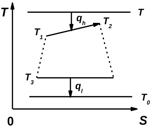
3Figure 2. The T-S diagram of an irreversible Braysson heat engine cycle.
The cycle of the working substance in the heat engine consists of one isobaric branch, one isothermal branch, and two irreversible adiabatic branches, as shown in Fig. 2, where Ti (i =1,2 and 3)
Braysson cycle is assumed to be an ideal gas and the heat transfer is assumed to obey Newton’s law, the rates of the heat transfer qh and ql absorbed from the heat reservoir at temperature T and released to
the heat sink at temperature T0 are [40-42]
1 1 1 1
( 1)
( 1)
ln
h p
U AT x
q m c T x
y
(9)
and
2 2( 3 0)
l
q U A T T , (10)
respectively, where U1and U2 are the heat-transfer coefficients between the working substance and the heat reservoirs at temperatures T and T0, respectively, Ai (i=1 and 2) are the corresponding
heat-transfer areas, m
and cpare the mass flow rate and specific heat at constant pressure of the working substance, respectively, y(TT1) / (TT x1 ), and xT2 /T1 is the isobaric temperature ratio. The overall heat-transfer area of the heat engine is
1 2
e
A A A . (11)
According to the second law of thermodynamics, one has
2 2 3 0 3
ln( ) ( ) / 0
p
m c x U A T T T
. (12)
In the investigation on the optimum performance of an irreversible Braysson heat engine, it is very significant to further consider the influence of irreversibility within the cycle. Using Eq. (12), we may introduce a parameter
2 2 3 0 3 2 2 3 0
1 1 3
( ) / ( ) ln
ln ln
i
p
U A T T T U A T T y
R
U AT x
m c x
(13)
to describe the influence of the irreversibility of the working substance on the performance of the heat engine. For a practical Braysson heat engine, Ri >1. When the internal irreversibility of the heat engine
is negligible, Ri=1 and the cycle is endoreversible.
By using the above equations, the efficiency of the Braysson heat engine can be expressed as
3
1
ln
1 1
( 1)
l i
H
h
q R T x
q T x
Substituting Eqs. (10), (11), (13), and (14) into Eq. (9), the rate of the heat transfer qh can be expressed as
1
1 2
1 1 0
( / ) ln
ln
( 1) ( 1) / (1 ) ln
e h i H U A q
U U R x
y
T x T x RT x
. (15)
Using Eq. (15) and the extreme condition( / 1) , 0 e h
H T A q
, we can prove that for given Ae and qh, the optimal efficiency of the heat engine is given by
0 0
1 1 1 2
ln
1 1
( 1)(1 ) (1 ) / ( ) ln / ln ( ) / ( )
i H
h i e i
R T x T
T x d d q U R A y x U R U d
, (16)
where
0.5
1 2
1 1 1
( / ) ln
( 1) / ( )( ) ln
i
U R U x d
TT x T T T T x y
, (Ae/A1) 1 ( U R U d1 i/ 2 )(ln / ln )x y , and T1 is
determined by the following equation:
1 1 1 2 ( 1) ln ln e h i
U A T x q U R y x U d
. (17)
As illustrated in Fig. 1, a part of the waste heat produced in the fuel cell is directly released as hat leak to the environment, which may be expressed as [43, 44]
0
( )
Loss L L
q U A TT , (18)
where ULis the convective and/or conductive heat-leak coefficient and AL is the effective heat-transfer area. According to Fig. 1 and Eq. (18), one has
h M Loss re
q H P q q
, (19)
and consequently, Eq. (17) may be written as
1
1 2 0 3 0
1
2
( 1)
(1 ) ( / 1) ( / 1)
ln ln
M i
T x
C j C T T C T T
U R y x U d (20)
where 1
1 e e
A h C
U A n F
, 0
2 1
L L
e
U A T C
U A
, and 0
3
1
(1 )
re re
e
U A T
C
U A
. By using Eqs. (16) and (19), the
1 2 0 3 0 0
1 2
1
(1 ) (1 ) ( / 1) ( / 1) ln / ln ( ) / ( )
i H
M i
R T
d C j C T T C T T y x U R U d
(21)
and
1 1(1 ) 2( / 0 1) 3( / 0 1)
H h H e H
P q U A C j C T T C T T
1 2 0 3 0 0
1 2
1
(1 ) (1 ) ( / 1) ( / 1) ln / ln ( ) / ( )
i
M i
R T
d C j C T T C T T y x U R U d
. (22)
[image:8.596.77.518.271.613.2]2.4 The efficiency and power output of the hybrid system
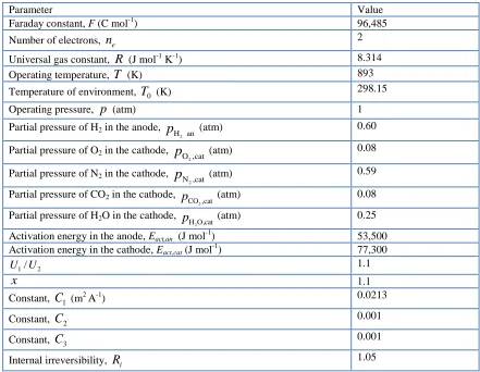
Table 1. Parameters used in the modeling of the MCFC-Braysson heat engine hybrid system.
Parameter Value
Faraday constant, F (C mol-1) 96,485
Number of electrons, ne 2
Universal gas constant, R (J mol-1 K-1) 8.314 Operating temperature, T (K) 893 Temperature of environment, T0 (K) 298.15
Operating pressure, p (atm) 1
Partial pressure of H2 in the anode,
an H2
p (atm) 0.60
Partial pressure of O2 in the cathode, O ,cat 2
p
(atm) 0.08Partial pressure of N2 in the cathode, N ,cat 2
p
(atm) 0.59Partial pressure of CO2 in the cathode, CO,cat 2
p (atm) 0.08
Partial pressure of H2O in the cathode, HO,cat 2
p (atm) 0.25
Activation energy in the anode, Eact,an (J mol
-1
) 53,500
Activation energy in the cathode, Eact,cat (J mol-1) 77,300
1/ 2
U U 1.1
x 1.1
Constant, C1 (m2 A-1) 0.0213
Constant, C2 0.001
Constant, C3 0.001
Internal irreversibility, Ri 1.05
Combining Eqs. (1), (6), (7), (19), (21), and (22) yields the expressions of the efficiency and power output of the hybrid system as
2 3 0
1
( )( / 1)
= = M H 1
M H M
C C T T
P P
P
C j
H H
(23)
= M H
e
jA h
P P P
n F
. (24)
It is seen from Eqs. (23) and (24) that the performance of the MCFC-Braysson heat engine hybrid system depends on a set of thermodynamic and electrochemical parameters such as the working temperature, current density, synthesized parameters Ci (i=1, 2 and 3), partial pressures of electrodes gas compositions, and so on. Below, numerical calculations are carried out based on the data summarized in Table 1 [24, 34, 36] and these parameters are kept constant unless mentioned specifically.
3. GENERAL PERFORMANCE CHARACTERISTICS AND MULTI-OBJECTIVE OPTIMIZATION
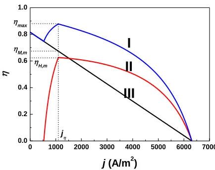
Using Eqs. (6), (7), (13)-(15), (23), and (24), one can generate the curves of the efficiency and power output of the MCFC, Braysson heat engine, and hybrid system varying with the current density, as shown in Figs. 3 and 4, respectively, where P* P A/ is the power density of the hybrid system.
It is clearly seen from Figs. 3 and 4 that there are a maximum efficiency max and a maximum power density Pmax* for the hybrid system and the corresponding current densities are j and jP , respectively. It is also seen from Figs. 3 and 4 that in the region of j j, both the efficiency and the power output of the hybrid system will decrease as the current density j is decreased, while in the region of j jP, both the efficiency and power output of the hybrid system will decrease as the
current density j is increased. Obviously, the regions of j j and j jP are not the optimally operating region of the hybrid system. Thus, the optimally operating region of the current density j for the MCFC-Braysson heat engine hybrid system should be determined by
0 1000 2000 3000 4000 5000 6000 7000
0.0 0.2 0.4 0.6 0.8 1.0
j (A/m2)
j
max
M,m
H,m
I
II
III
Figure 3. The curves of the efficiencies of the MCFC, Braysson heat engine, and hybrid system varying with the current density, where j is the current density at the maximum efficiency
max
of the hybrid system, M,m and H,m are the efficiencies of the MCFC and Braysson heat
[image:9.596.187.404.498.670.2]
0 1000 2000 3000 4000 5000 6000 7000
0 1000 2000 3000 4000
jP
P
* (
W
/m
2 )
j (A/m2)
P* max
P*H,m
P* M,m
I
II
III
Figure 4. The curves of the power densities of the MCFC, Braysson heat engine, and hybrid system varying with the current density, whereP*P/A, jP is the current densities at the maximum power density Pmax* , PM*,mand PH*,m are the power densities of the MCFC and Braysson heat engine at Pmax* , and curves I, II, and III correspond to the same cases as those in Fig. 3.
0.0 0.2 0.4 0.6 0.8 1.0
0 800 1600 2400 3200 4000
P
*
(
W
/m
2
)
P* max
P*
max
P
Z*1
I
II
[image:10.596.159.436.74.268.2]III
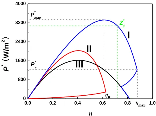
Figure 5. The power density versus efficiency curves of the MCFC, Braysson heat engine, and hybrid system, where curve I, II, and III correspond to the same cases as those in Fig.3.
P
j j
j . (25)
To further understand the performance characteristics of the hybrid system, one can plot the power density versus efficiency curves of the hybrid system, as shown in Fig. 5, where Pand
[image:10.596.166.436.393.595.2]
efficiency. According to the optimum criterion of the current density and Fig. 5, one can further determine the optimum regions for the efficiency and power output as
max
P
(26)
and
max
P P P . (27)
It is clearly seen from Figs. 3-5 that in the optimally operating region, the efficiency and power output of the hybrid system are always larger than those of the MCFC or Braysson heat engine. It shows once again that the application of the hybrid system may effectively improve the performance of the MCFC.
It should be pointed out that when the hybrid system is operated in the optimum region, the power output will decrease as the efficiency is increased, and vice versa. Generally, the power output P is very small compared with Pmax when the hybrid system achieves its maximum efficiency max . Thus, the problem how to reasonably choose both the efficiency and the power output in the optimal region of j j jP will become very important in the practical optimum design and operation of the hybrid system. For this purpose, we may introduce a multi-objective function which is defined as the product of the efficiency with a weighting factor and the power output [45-47], i.e.,
P
Z , (28)
where 0 and its concrete value can be chosen according to the different requirements for the efficiency and power output of the MCFC-Braysson heat engine hybrid system. When one pays equal attention to both the efficiency and power output, one can choose 1. Below, we will take
1
as an example to discuss the choice problem of the optimal current density.
According to Eqs. (23), (24), and (28), we can generate the curve of Z1* ~ j, as shown in Fig. 6, where Z1* Z1/A and
1
Z
j is the current density corresponding to Z1*,max. It is seen from Fig. 6 that *
1
Z first increases and then decreases with the increase of the current density. This means that there always exists a maximum value for Z1*. Fig. 6 clearly shows that
1
Z P
j j j . Thus, the optimal operation region j j jPcan be subdivided according to the different requirements for both the
efficiency and the power output. In general, for a practical fuel cell-heat engine hybrid system, the more attention will be paid on the power output than on the efficiency so that the operation region of the current density should be chosen in the region of
P
Z j j
j
0 1000 2000 3000 4000 5000 6000 7000 0.0
0.2 0.4 0.6 0.8 1.0
j
(A/m
2)
max
0 1000 2000 3000 4000
P
*
,
Z
*
1
(
W
/m
2
)
j
Z*1,max
jP
jZ
1
P*max
Figure 6. The curves of the efficiency, power density and multi-objective function of the hybrid system varying with the current density, where j, jP, and jZ1are the current densities at the
maximum efficiency, power density, and multi-objective function, respectively.
4. DISCUSSION
4.1 Effects of the operating temperature T
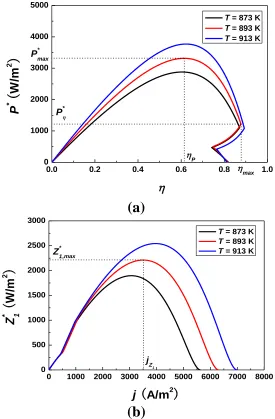
The operating temperature of the system is an important parameter because it directly affects the various overpotentials of the fuel cell as well as the performance of the heat engine. Fig. 7 clearly shows the effects of the operating temperature on the performance of the hybrid system and the multi-objective function.
It can be seen from Fig. 7 (a) that the maximum power density and its corresponding efficiency as well as the maximum efficiency and its corresponding power output increase as the operating temperature is increased.
Fig. 7 (b) shows that the maximum value of the multi-objective function and its corresponding current density increase as the operating temperature is increased.
[image:12.596.143.461.73.303.2]
0.0 0.2 0.4 0.6 0.8 1.0
0 1000 2000 3000 4000 5000
P
*
(
W
/m
2
)
T = 873 K
T = 893 K
T = 913 K
max
P* max
P
P*
(a)
0 1000 2000 3000 4000 5000 6000 7000 8000 0
500 1000 1500 2000 2500 3000
Z
*
(
1W
/m
2
)
j (A/m2)
T = 873 K
T = 893 K
T = 913 K
jZ
1
Z*1,max
[image:13.596.162.437.80.499.2](b)
Figure 7. The effect of the operating temperature on (a) the performance of the hybrid system and (b) the multi-objective function.
4.2 Effects of
x
, R, C and 2 C3(1) When x1, the Braysson heat engine cycle becomes a Carnot cycle. In this case, Eqs. (21) and (23) may be, respectively, simplified as [48]
0 1 2 0
1 1
/ (1 ) ( / 1)
H
M
T T m j m T T
(30)
and
2 0
0 1 2 0
( / 1) 1
[1 ] 1
/ [(1 ) ( / 1)]
M M
M
m T T
j T T m j m T T
where
22 1 2
1U A / U U
U
K e ,
0 1 0 e A h m n FKT
, and 3 3
2 0 0 (1 ) / ( ) re re e
U A U A
m
A h n FT
.
(2) When Ri 1, the influence of irreversibility within the Braysson cycle is negligible. In such a case, Eqs. (21) and (23) may be, respectively, simplified as
1 2 0 30 0
1 2
1
(1 ) (1 ) ( / 1) ( / 1) ln / ln ( ) / ( )
i H
M
R T
d C j C T T C T T y x U U d
(32)
and
2 3 0
1
( )( / 1)
= M H 1 M C C T T
C j
, (33)
(3) When C2 0, the heat leak from the MCFC to the environment is negligible. Eqs. (21), (23), and (24) may be, respectively, simplified as
1 3 0 0
1 2
1
(1 ) (1 ) ( / 1) ln / ln ( ) / ( )
i H
M i
R T
d C j C T T y x U R U d
, (34)
3 0
1
( / 1)
1
M H M
C T T C j
, (35)
and
3 0
1
( / 1)
1
M H M
e
C T T jA h
P
n F C j
. (36)
(4) When C3 0, the irreversible losses in the regenerator are negligible. Eqs. (21), (23), and (24) may be, respectively, simplified as
1 2 0 0
1 2
1
(1 ) (1 ) ( / 1) ln / ln ( ) / ( )
i H
M i
R T
d C j C T T y x U R U d
, (37)
2 0
1
( / 1)
1
M H M
C T T C j
, (38)
2 0
1
( / 1)
= M H 1 M
e
C T T jA h
P
n F C j
. (39)
(5) When C2 0 and 0 3
C , the heat leak from the MCFC to the environment and the heat losses in the regenerator are negligible. Eqs. (34)-(36) or Eqs. (37)-(39) can be further simplified as
0
1 1 2
1
(1 ) (1 ) ln / ln ( ) / ( )
i H
M i
R T
d C j y x U R U d
, (40)
(1 )
M H M
, (41)
and
= M H(1 M)
e
jA h P
n F
. (42)
5. CONCLUSIONS
With the help of the model of an MCFC-Braysson heat engine hybrid system including multi-irreversibilities, analytical expressions for the efficiency and power output of the hybrid system are derived, from which the general characteristics of the hybrid system are revealed and the upper and lower bounds of the optimized values for some main parameters, such as the current density, power output, and efficiency, are determined. The problem how to give consideration to the efficiency and power output in the optimal region of the current density is researched. The influence of the irreversibilities on the performance of the hybrid system is discussed in detail, so that the optimum performance of the hybrid system operated at several special cases are directly derived. The results obtained here may provide some theoretical basis for the optimal design and operation of practical MCFC-heat engine hybrid systems.
ACKNOWLEDGEMENTS
This work has been supported by the National Natural Science Foundation (No. 51076134) and the Fundamental Research Fund of Xiamen Universities (No. 201112G006), People’s Republic of China.
References
1. J. Brower, F. Jabbari, E. M. Leal, T. Orr, J. Power Sources, 158 (2006) 213. 2. G. J. K. Acres, J. Power Sources, 100 (2001) 60.
6. G. Cacciola, V. Antonucci, S. Freni, J. Power Sources, 100 (2001) 67.
7. R. O’Hayre, S. W. Cha, W. Colella, F. B. Prinz, Fuel Cell Fundamentals. New York: John Wiley & Sons. Inc.; 2006.
8. P. Tomczyk, J. Power Sources, 160 (2006) 858. 9. A. Dicks, A. Siddle, J. Power Sources, 86 (2000) 316. 10.P. S. Pak, Y. D. Lee, K. Y. Ahn, Energy, 34 (2009) 1903.
11.R. Rashidi, P. Berg, I. Dincer, Int. J. Hydrogen Energy, 34 (2009) 4395. 12.P. Lunghi, R. Bove, U. Desideri, J. Power Sources, 118 (2003) 108. 13.V. Verda, F. Nicolin, Int. J. Hydrogen Energy, 35 (2010) 794. 14.F. Jurado, J. Power Sources, 111 (2002) 121.
15.Y. Zhao, J. Chen, J. Power Sources, 186 (2009) 96. 16.O. S. Süslü, İ. Becerik, Energy Fuels, 23 (2009) 1858. 17.X. Zhang, J. Chen, Int. J. Hydrogen Energy, 35 (2010) 284.
18.D. Sánchez, R. Chacartegui, M. Torres, T. Sánchez, J. Power Sources, 192 (2009) 84. 19.T. H. Frost, A. Anderson, B. Agnew, Proc. Inst. Mech. Eng. Part A, 211 (1997) 121. 20.S. Zheng, J. Chen, G. Lin, Renew. Energy, 30 (2005) 601.
21.J. Zheng, L. Chen, F. Sun, C. Wu, Exergy, 2 (2002) 380.
22.J. Zheng, L. Chen, F. Sun, C. Wu, Int. J. Therm. Sci., 41 (2002) 201. 23.C. Wu, Proc. Inst. Mech. Eng. 213A (1999) 1.
24.J. Brouwer, F. Jabbari, E. M. Leal, T. Orr, J. Power Sources, 158 (2006) 213. 25.M. Baranak, H. Atakül, J. Power Sources, 172 (2007) 831.
26.C. Y. Yuh, J. R. Selman, J. Electrochem. Soc., 138 (1991) 3642. 27.H. Zhang, G. Lin, J. Chen, Int. J. Hydrogen Energy, 36 (2011) 4015.
28.R. H. Perry, C. H. Chilton, Chemical engineering’s handbook. 5th ed. Tokyo: McGraw Hill Kogakusha, Ltd; 1973.
29.Y. Zhao, C. Ou, J. Chen, Int. J. Hydrogen Energy, 33 (2008) 4161.
30.J. A.Dean, Lange’s Handbook of Chemistry, 13th Ed. New York: McGraw Hill Book Company; 1985.
31.H. Zhang, S. Su, G. Lin, J. Chen, Int. J. Electrochem. Sci., 6 (2011) 2566. 32.H. Zhang, G. Lin, J. Chen, Int. J. Hydrogen Energy, 35 (2010) 10851. 33.A. Liu, Y. Weng, J. Power Sources, 195 (2010) 1872.
34.J. H. Koh, B. S. Kang, H. C. Lim, AIChE J., 47 (2001) 1941. 35.A. Liu, Y. Weng, J. Power Sources, 195 (2010) 204.
36.S. Campanari, P. Chiesa, G. Manzolini, Int. J. Greenhouse Gas Control, 4 (2010) 441. 37.C. Hitchings, Fuel Cell Handbook. 6th ed., Virginia: EG&G Technical Services, Inc.; 2002. 38.J. Chen, J. Phys. D: Appl. Phys., 27 (1994) 1144.
39.M. Bojic, Energy Convers. Manage., 381997;:1877-1880. 40.X. Chen, B. Lin, J. Chen, Energy Fuels, 23 (2009) 6079. 41.L. Wu, G. Lin, J. Chen, Renew. Energy, 35 (2010) 95.
42.Y. Zhou, S. K. Tyagi, J. Chen, Int. J. Therm. Sci., 43 (2004) 1101.
43.P. Holtappels, H. Mehling, S. Roehlich, S. S. Liebermann, U. Stimming, Fuel Cells, 5 (2005) 499. 44.P. G. Bavarsad, Int. J. Hydrogen Energy, 32 (2007) 4591.
45.Z. Yan, J. Eng. Thermal Energy Power, 4 (1989) 1. 46.W. Na, B. Gou, J. Power Sources, 166 (2007) 411.
47.S. M. C. Ang, D. J. L. Brett, E. S. Fraga, J. Power Sources, 195 (2010) 2754. 48.H. Zhang, G. Lin, J. Chen, Int. J. Electrochem. Sci., 6 (2011) 4714.