Abstract: Minimization of power loss is the first priority of the power companies. Generally power loss is directly proportional to the reactive power demand and minimization of this is known as reactive power optimization (RPO). In this paper we are trying to minimize the reactive power loss with help of distributed generation. Distributed generation provides active as well as reactive power locally so, there is no need of taking the reactive power from the generator consequently reactive power loss minimizes. Now problem arises that where to place the distributed generation to have minimum power loss. To find the optimal location of the distributed generation, we have used particle swarm optimization algorithm (PSO). For that we have defined the fitness function as well as constraints. Constraints limits the value of variable within the defined range. Fitness function is sum of real power loss index, reactive power loss index and voltage deviation index. We have also used genetic algorithm just to compare the results and to find which one is better out of genetic algorithm and PSO. RPO increases the power transfer capability, reduces the line loss and boost the system stability therefore it can be applied in the distribution network.
Keywords: Distributed Generation, Genetic Algorithm, PSO, RPO.
I. INTRODUCTION
Power systems are large and complex electrical networks. In power system, generations are at few specific points but loads are dispersed over entire network. In between generations and loads, there is transmission and distribution system. Generally in power system, load continuously varies so to adjust this variation in the system, there is also continuous power flow analysis.
Power system characteristics:
It must supply power to all the customer. All the time it should supply the power.
It should adjust itself to meet the load variation. Power should be of acceptable quality.
Power should be affordable to maximum of the population.
It should fulfill all the safety requirements.
To know the state of power system, power flow analysis (PFA) is done at regular interval of time. It is necessary to adjust the system according to load variation.
Revised Manuscript Received on August 05, 2019.
Amar Nath Patel, student of University Institute of Technology, Rajiv Gandhi Prodyogiki Vishwavidyalaya Bhopal Madhya Pradesh.
Mrs. Shobhna Jain is assistant professor in department of Electrical and Electronics Engineering of University Institute of technology, Rajiv Gandhi Prodyogiki Vishwavidyalaya Bhopal.
PFA determines the voltage and its angle at each bus. After finding complex voltage, we finds active as well as reactive power and then line loss. Generally most of the load are inductive in nature so it is common to see the large demand of reactive power. We know that reactive power produces ohmic losses which decreases the efficiency of the system and moreover it also disturbs the voltage profile because reactive power is directly proportional to the voltage difference. So owing to above problem, now it become necessary to optimize the reactive power of overall system. For optimization of reactive power, we generally use power electronic devices but in this paper we use distributed generation (DG) which supplies not only reactive but also active power that’s why it further reduces the line loss.
Now problem arises that on which bus we should place the DG so that maximum optimization can be achieved. To solve this problem we have to use optimization techniques. Here we cannot use linear programming because it can be used only when objective function is of linear equation. In this paper, particle swarm optimization (PSO) algorithm has been used to find the optimal placing of the distributed generation. PSO is a part of swarm intelligence of the artificial intelligence. It mimics the social behaviour of birds flocking. It resemble with the process that birds use to find their food. To find the optimum location of DG we have to do mathematical formulation of the reactive power optimization (RPO).
II. MATHEMATICALFORMULATIONOF
REACTIVEPOWEROPTIMIZATION
Reactive power optimization is done to minimize the system loss, to improve the voltage profile and finally to save the operating cost of the system. For that we have to formulate our problem mathematically. In the formulation, we have three parts that is objective function, power constraints and variable constraints equations.
A. Objective function
Our objective of RPO is to minimizes the active power loss in distribution network and that can be written as
P
loss= ∑G
pq(V
p 2+ V
q 2- 2 V
pV
qCos δ
pq)
Where p and q are the bus number and sigma sign represents summation of losses of all the lines in entire distribution network.
Particle Swarm Optimization Algorithm Based
Reactive Power Optimization in Distribution
Network
B. Fitness Function
Fitness function is required to calculate the fitness of each particle in PSO and that is the summation of real power loss index, reactive power loss index and voltage deviation index with coefficient 0.5, 0.35 and 0.15 respectively.
Lets,
Summation of active power loss without DG = P1 Summation of active power loss with DG = P2 Summation of reactive power loss without DG = Q1 Summation of reactive power loss with DG = Q2 Reference voltage = V1
Voltage when DG is not installed = V2 So,
Real power loss index =
Reactive power loss index =
Voltage deviation index = min
Then
Fitness function = min F = 0.5
+
0.35+
0.15
C. Power Constraints
Active and reactive power balance equation is equality Constraints.
P
p =V
p q(G
pqCos δ
pq+ B
pqSin δ
pq)
Q
p =V
p q(G
pqCos δ
pq- B
pqSin δ
pq)
Where Pp and Qp are active and reactive power injected at bus “p”. Vp and Vq are voltages at buses “p”and “q”. N is the total number of buses. Gpq, Bpq and δpq are conductance, susceptance and voltage angle difference between buses “p” and “q”.
D. Variable Constraints
These constraints are also known as inequality constraints and those are:
V
gp minV
gpV
gp maxV
p minV
pV
p maxQ
gp minQ
gpQ
gp maxS
p minS
pS
p maxT
p minT
pT
p maxWhere Vgp is the generator terminal voltage; Vgp max, Vgp min are the upper limit and lower limit of the generator terminal voltage; Vp is the voltage of bus p; Vp max, Vp min are the upper limit and lower limit of the voltage amplitude of bus p; Q is
the generator reactive power output; Qgp max, Qgp min are the upper limit and lower limit of the generator reactive power output; Sp is DG power output; Sp max, Sp min are upper and lower limit of DG power output; Tp is the position of the adjustable transformer tap; Tp max, Tp min are upper and lower limit of the transformation ratio of transformer.
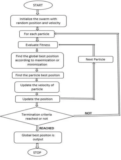
III. PARTICLESWARMOPTIMIZATION PSO is swarm intelligence based optimization algorithm. Initially we take collection of some random values as the solution of the problem, that collection is considered as swarm and each value of that collection is known as particle. Now each particle have its own position and velocity. For each particle, we evaluate the fitness value in each iteration and then find their best position (pbest) as well as global best value (gbest). In every iteration, each particle updates its position as well as their velocity according to following formula.
[image:2.595.321.528.451.724.2]Where ω is inertial weight; V is velocity; pid is the personal best; pgd is the global best; c1 and c2 are two positive constants referred to as cognitive and social parameters respectively. r1 and r2 are two random numbers between zero and one; t represents iteration number; ᵡ represents position. We have taken the value of C1 = 1.2, C2 = 0.12 and ω = 0.3. Flowchart of PSO is given below.
IV. GENETICALGORITHM
The process of developing and applying a genetic algorithm remain same to the biological evolutionary process. GA is basically implemented as a computer simulation program which involves a population of chromosomes containing possible solution candidates to an optimization problem; then the candidates evolve towards better solution. The process of evaluation begins from population of randomly produced individuals and then proceeds forward from one generation to next. In each generation, a subset of the population is picked to reproduce in such a manner that the new population produced will possess better qualities than the old one. The selection procedure utilized for choosing a subset is usually random, where the probability of choice is directly proportional to the fitness function.
The process of reproduction involves random pairing of all selected individual and generation of two new individuals by performing crossover, in which the initial n bits (where n is random number) of the parents are exchanged. This results in the generation of new chromosomes that are called offsprings, there is always a slight possibility of one of the genes in the offsprings mutating to take a new value. This process may lead us to believe that generating new populations from only two parents may cause loss of the best chromosome from the last population. Therefore, at least one of a generation best solution are copied without any change to a new population in order to retain the best solution in the succeeding generation. An algorithm may terminate in two way, firstly when it has got maximum generation and secondly if it has achieved desired level of fitness value. In case an algorithm gets terminated because of maximum number of generation, the solution obtained may not be satisfactory.
[image:3.595.309.545.68.301.2]V. FLOWCHARTOFOPTIMIZATIONPROCESS
Fig. 2.Flow chart of optimization Process.
[image:3.595.314.539.388.611.2]VI. RESULTS
Fig. 3.Variation of best value and mean value with number of generation in genetic algorithm.
[image:3.595.60.274.465.755.2]figure 2, shows that how best value and mean value of fitness function is varying with respect to generation in genetic algorithm.
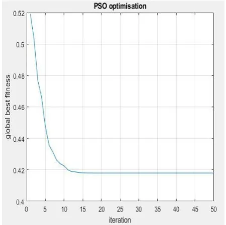
Fig. 4.Graph between iteration and global best fitness value in PSO.
Fig. 5.Comparison of bus voltage magnitude. Figure 4, tells about each bus voltage before reactive power optimization and after optimization by PSO and genetic algorithm so finally we can say that PSO is better than genetic algorithm in reactive power optimization because we are getting better voltage level by PSO. Desire range of voltage is from 0.95 to 1.1 per unit.
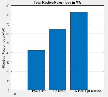
[image:4.595.315.539.49.246.2]Fig. 6.Bar graph of reactive power loss comparison. In figure 5, we have shown the power loss comparison due to flow of reactive component of load current. Reactive power loss is minimum in case of PSO optimization compared to genetic algorithm and it is maximum in without optimization case.
Fig. 7.Bar graph of active power loss comparison. In figure 6, we have shown the power loss comparison due to flow of active component of load current. Active power loss is minimum in case of PSO optimization compared to genetic algorithm and it is maximum in without optimization case.
VII. CONCLUSION
In this paper we have tried to minimize the power loss due to reactive power flow in the lines. For this we have used DG, because it not only compensate the reactive power but also can provide active power in large amount which further reduces the line loss. To find the optimal location of the DG, PSO algorithm has been used. Our objective function is minimum power loss. We have compared the results of PSO with genetic algorithm and find that PSO provides better optimization than genetic algorithm. Generally, RPO is done to have good voltage profile, more power transfer capability, less power loss and improved system stability. In this we have used basic PSO algorithm but for more improvement, we can use advance version of PSO. We should also compare the result of PSO with other optimization algorithms so that we can get best algorithm for RPO. We should also think about power quality and for that we can use unified power quality conditioner at optimized location.
REFERENCES
1. Chao Wang,“Reactive “Power Optimization Based on Particle Swarm Optimization Algorithm in 10kV Distribution Network,” International Conference in Swarm Intelligence ICSI 2011: Advances in Swarm Intelligence pp 157-164
2. Gibson H.M. Sianipar, “Optimization of Reactive Power and Voltage
Control in Power System Using Hybrid Artificial Neural Network and Particle Swarm Optimization,” 2018 2nd International Conference on Applied Electromagnetic Technology (AEMT)
3. Hao Wang,“Reactive power optimization of power system based on
improved particle swarm optimization,” 2011 4th International Conference on Electric Utility Deregulation and Restructuring and Power Technologies (DRPT)
4. Wen Zhang,“Reactive power optimization based on PSO in a practical
[image:4.595.54.283.361.567.2]Author-1 Photo
Author-2 Photo
AUTHORSPROFILE
Amar Nath Patel is a student of University Institute of Technology, Rajiv Gandhi Prodyogiki Vishwavidyalaya Bhopal Madhya Pradesh. He is in fourth semester of Master of Engineering in power system and graduate aptitude test in engineering qualified scholar. He has completed his graduation from Lovely Professional University Phagwara Punjab.