UNIVERSITI TEKNIKAL MALAYSIA MELAKA
STUDY ON CUTTING PARAMETER ON KERF WIDTH USING
WEDM OF INCONEL 718
This report submitted in accordance with requirement of the Universiti Teknikal Malaysia Melaka (UTeM) for the Bachelor Degree of Manufacturing Engineering
(Manufacturing Management) (Hons.)
by
CHE MUHAMAD HAMZAH BIN CHE NOR
B051110309 900730-03-5031
I hereby, declared this report entitled "Study On Cutting Parameter On Kerf Width Using Wedm Of Inconel 718" is the results of my own research except as cited in references.
Signature
Author's Name
Date
~
...
~... ..
CHE MUHAMAD HAMZAH BIN CHE NORThis report is submitted to the Faculty of Manufacturing Engineering of UTeM as a partial fulfillment of the requirements for the degree of Bachelor of Manufacturing Engineering (Management) (Hons.). The member of the supervisory is as follow:
(En Mohd Shahir Kasim)
OR. MOHD SHAHIR BIN KASIM
Lecturer . ,· o
factur\ng Engtnee. m,, faculty of .Maknu.I< \Malaysia Me\;kz
Univers1tl Te ni .a
ABSTRAK
Artikel ini membincangkan kesan pemboleh ubah pemotongan terhadap lebar Kerf
menggunakan komputer kawalan berangka mesin nyahcas elektrik (WEDM)
terhadap Inconel 718. Tiga pemboleh ubah yang diguna adalah perbezaan volt, kadar
suapan dan arus yang dimanipulasi di dalam eksperimen ini. Reka bentuk
eksperimen disiapkan menggunakan kaedah gerak balas permukaan. Analisis varians
(ANOVA) menunjukkan bahawa kadar suapan banyak memberi kesan tehadap lebar
Kerf berbanding pemboleh ubah lain yang dipakai di dalam eksperimen ini.
Pengoptimuman dilakukan selepas eksperimen disahkan menggunakan pemboleh
ubah rawak dan pemboleh ubah optimum. Ralat yang didapati ketika menggunakan
pemboleh ubah rawak adalah 5% dan 4% ketika menggunakan pemboleh ubah
optimum. Kombinasi pemboleh ubah yang terbaik untuk mengoptimum lebar Kerf
adalah kadar suapan 0.86 mm/min, V 41 V dan I 7A untuk mendapatkan lebar Kerf
ABSTRACT
This article considers the study of cutting parameter on Kerf width using WEDM of
Inconel 718. Three numerical parameters like voltage gap, feed rate, and current are
being manipulated in this experiment. Designs of experiment are done by using the
response surface methodology. ANOVA shows that feedrate heavily affect the size
of Kerf width compared to other parameter used in this experiment. Optimization
was done after the experiment has been validated by using the random parameter and
optimized parameter. The error obtained when using random parameter is 5% and
4% for the optimized parameter. The best combination of parameter to optimize the
Kerf width are fz 0.86 mm/min, V 41 V and I 7A in as to obtain a Kerf width of
DEDICATION
To everyone that contributes to this research and my friend that has been helping me
ACKNOWLEDGEMENT
First of all, I would like to thank ALLAH for giving me the strength to get this paper
done. To my supervisor, Dr. Mohd Shahir Bin Kasim in giving his advices that is
good for me and my research and his belief in me to finish this research in the given
time. Not to mention that all my friends those have been helping me in completing
this research and my beloved parents that gives all their support in completing my
TABLE OF CONTENTS
ABSTRAK i
ABSTRACT ii
DEDICATION iii
ACKNOWLEDGEMENT iii
TABLE OF CONTENTS v
LIST OF TABLES viii
LIST OF FIGURES xi
LIST OF ABBREVIATIONS, SYMBOLS AND NOMENCLATURE xii
CHAPTER 1: INTRODUCTION 1
1.1 Background of study 1
1.2 Definition and parameters 2
1.3 Problem statement 3
1.4 Scope of research 4
1.5 Objective 4
1.6 Thesis organization 5
CHAPTER 2 : LITERATURE REVIEW 6
2.1 Introduction 6
2.1.1 Wire EDM 6
2.1.2 Pulse-on time and pulse-off time 6
2.1.3 Surface roughness 7
2.1.4 Kerf width 7
2.2 Previous research in Wire EDM 9
2.2.1 Material, tool and work piece used 11
2.2.2 Stock size and result 12
2.2.3 Parameter 14
2.2.4 Finding 15
2.2.5 Equipment 17
2.3 Strategy/parameter 19
2.3.1 Feed rate 19
2.3.2 Current 20
2.3.3 Voltage 20
2.4 Research gap 25
2.5 Summary 26
CHAPTER 3 : METHODOLOGY 27
3.1 Introduction 27
3.2 Wire 29
3.2.1 Characteristic 30
3.2.2 Thermal 30
3.2.3 Mechanical properties 30
3.3 Work piece material 31
3.3.1 Chemical content 32
3.3.2 Mechanical properties 32
3.4 Cutting parameter setup 33
3.4.1 Parameter setting 33
3.4.2 Factors selection for range of parameter. 34
3.5 Design of computer numerical control (CNC) program 35
3.6 Design of experiment 36
3.7 Step to design the experiment 36
3.7.1 Design the experiment 36
3.7.2 Define factor and variable constraints 37
3.7.3 Add interaction term 37
3.7.4 Determine the number of run 37
3.7.5 Check the design 37
3.7.6 Gather and enter the data 38
3.7.7 Analyse the result 38
3.8 DOE matrix 38
3.9.1 Sample preparation 39
3.9.2 Wire EDM machine preparation 39
CHAPTER 4 : RESULT AND DISCUSSION 45
4.1 Results 45
4.2 Analysis of Variance (ANOVA) 46
4.3 Mathematical model 47
4.4 Factor affecting Kerf Width 51
4.4.1 Voltage Gap and Feed rate (current is set to constant) 51
4.4.2 Current and Feed rate (voltage is set to constant) 52
4.4.3 Perturbation plot 53
4.5 Optimization 54
4.6 Validating the optimized parameter 55
CHAPTER 5 : CONCLUSION AND RECOMMENDATION 58
5.1 Conclusion 58
5.2 Suggestion and Improvement for Future Research 59
5.3 Project Potential 60
LIST OF TABLES
Table 2.1: Material, tool and work piece used ... 11
Table 2.2: Stock size and result ... 12
Table 2.3: Parameter ... 14
Table 2.4: Finding ... 15
Table 2.5: Equipment ... 17
Table 2.6: Design of experiment (DOE) used to perform analysis ... 18
Table 3.1: Composition of brass (Shackelford, 2013) ... 30
Table 3.2: Thermal properties of Wire Brass (Shackelford, 2013). ... 30
Table 3.3: Mechanical properties of brass (Shackelford, 2013)... 31
Table 3.4: Chemical composition (wt%) of Inconel 718 (Li et al., 2013) ... 32
Table 3.5: Physical properties of Inconel 718 (Li et al., 2013). ... 33
Table 3.6: Parameter used for the experiment ... 34
Table 3.7: DOE matrix ... 39
Table 4.1: Result of Kerf width ... 45
Table 4.2: ANOVA table ... 46
Table 4.3: Result of Kerf Width ( average error is 5%) ... 47
Table 4.4: Optimized parameter ... 54
[image:11.595.113.528.132.526.2]Table 4.5: estimated set of optimized parameter... 54
LIST OF FIGURES
Figure 2.1: Kerf width in Wire EDM machining (Newton, 2008)... 8
Figure 2.2: Range of parameter (current) ... 21
Figure 2.3: Range of parameter (wire feed rate) ... 22
Figure 2.4: Range of parameter (Voltage gap) ... 23
Figure 2.5: Current (A) versus Voltage gap (V) graph ... 24
Figure 2.6: Voltage gap (V) versus Wire feedrate (f) graph ... 25
Figure 3.1: Flow chart of study ... 29
Figure 3.2: Inconel 718 ... 31
Figure 3.3: Control panel of Mitsubishi WEDM RA 90 Series ... 40
Figure 3.4: E pack section in Mitsubishi WEDM RA 90 Series ... 40
Figure 3.5: Monitor section in Mitsubishi WEDM RA 90 Series... 41
Figure 3.6: Process flow for measuring Kerf width ... 42
Figure 3.7: Meiji optical microscope ... 43
Figure 3.8: Student measuring the material using optical microscope ... 43
Figure 3.9: Sample of image from Meiji optical microscope ... 44
Figure 4.1: Normal Plot of Residual ... 48
Figure 4.2: Normal Plot of Residual ... 49
Figure 4.3: Percentage Error between Experiment and Calculated Value of Kerf width with average error of 5% ... 50
Figure 4.4: 3D Surface of Voltage Gap versus feed rate versus Kerf... 51
Figure 4.5: 3D Surface of Current versus feed rate versus Kerf. ... 52
Figure 4.6: Perturbation plot... 53
Figure 4.7: Range of parameter used to obtain optimized Kerf width... 55
Figure 4.8: Kerf width using optimized parameter with error of 4% ... 56
LIST OF ABBREVIATIONS, SYMBOLS AND
NOMENCLATURE
CNC Computer Numerical Control
WEDM Wire Electrical Discharge Machining
RSM Response Surface Methodology
DOE Design of Experiment
CHAPTER 1
INTRODUCTION
1.1
Background of study
Wire-electrical discharge machining (WEDM) is a non-traditional machining process
in which a pulsed voltage difference between a wire electrode and a conductive work
piece initiates sparks which erode work piece material. Removing material in such a
way is often advantageous when the work piece material would be difficult to
machine with traditional machine tools due to high strength, hardness, toughness,
etcetera (Newton, 2008). Due to the process itself, WEDM are able to produce any
complex shape but at the loss of surface integrity and some other after effect like
Kerf width, Heat affected zone and etc. However, the selection of cutting parameters
for obtaining higher cutting efficiency or accuracy in WEDM is still not fully solved,
even with the most up-to-date WEDM machine. It is due to the hard to expect nature
of the process of WEDM. As a result, the relationships between the cutting
parameters and the process performance are hard to model accurately. The problems
arise although the machine itself is very up to date and some people hardly make a
research out of it. Nowadays, the application demands for a material that has best
properties in term of strength, corrosion and other properties. The composition of
material is then made according to the specific properties demanded. But, the
properties also bring disadvantages on what process should be chose to manufacture
the material so the composition of the material should be studied earlier before
making any decision. The ease and economy with which Inconel alloy 718 can be
fabricated, combined with good tensile, fatigue, creep, and rupture strength, have
use Inconel 718 as their main material are liquid fuelled rockets, casings and other
aircraft parts (Corp, 2007).
1.2
Definition and parameters
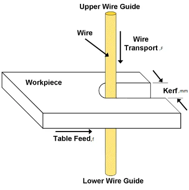
Kerf width can be described as the width of the slot made by any cutting machine as
it cuts. This term is widely used in engineering. It can be said as the working area for
any machining process. The term Kerf width in WEDM can be described as the area
that will be cut due to spark generated between anode and cathode. The effect of
parameters used in WEDM greatly affect the Kerf width itself so by manipulating
certain variables, the optimum Kerf width can be obtained. The Kerf width can be
easily calculated or measured using several devices like feeler gauge. The purpose of
feeler gauge is to measure the clearance between two parts. In laser cutting, it can be
found on how to measure the Kerf width for example. According to Williamson
(2011) , he uses a feeler gauge to measure the Kerf width and divides by the number
of cuts to get the particular Kerf width for the parameter used. Somehow, it is not
very practical to use the feeler gauge to measure the Kerf width on machined part
since the wire of the WEDM itself is very fine and the area being cut is very small.
Gupta et al. (2012) found that the effect of the Kerf width is small and it found that
the average Kerf width is about 310µm. While the feeler gauge only able to measure
about hundredth of millimetre, equipment are way better to be used to measure a
small range of area. An optical microscope is another fine masterpiece invented by
Zacharias Jansen around the year 1595 (Davidson, 2009) Nowadays, optical
microscope is one of the best ways to measure a fine length for example the Kerf
width on machined part which is very small and most of the length are µ sized.
Parameters that affect the Kerf width in WEDM are mostly related to the pulse-on
time and pulse-off time. According to Saha et al. (2013), the reason behind it is that
with the increase of discharge duration, the overcut during discharge is also
increased. From his analysis, the duration of discharge is increasing proportionally to
overcut/Kerf width. The cutting speed also affected by the discharge duration. The
parameter chose during WEDM can greatly affect the outcome of machined part for
properties that is crucial in optimizing the outcome of the WEDM. Most of the
previous researcher made a lot of contribution in determining the optimum parameter
for the best result in surface roughness of WEDM cut parts. M.S. Hewidy (2005)
made findings in getting the best surface roughness by manipulating the peak current.
It is found that the peak current will affect the surface roughness as it increase up to a
limit of 5A. Kumar and Singh (2012) found that open voltage have the greatest effect
of the surface roughness where it’s followed by some other parameter like wire
tension, pulse on time, servo voltage pulse off time, fluid pressure , feed rate, over
ride and wire feed . In his journal, Y.S.Liao (1997) found the table feed and pulse on
time have significant influence on the metal removal rate, the gap voltage and the
total discharge frequency. The gap width or Kerf width and the surface roughness are
influenced by the pulse-on time. To summarize the above previous research, the
parameters used greatly affect the outcome of the machined product while trying to
keep the objective result as best as possible. But in determining the best multi
objective parameter for the best configuration, the trade off need to be made where
the result is not that great compared to the single objective. Meaning that the surface
roughness and the Kerf width in one single experiment can be minimized a little bit
compared to the experiment that has a single purpose which is only to reduce surface
roughness (Kasim et al., 2013).
1.3 Problem statement
This research will focus on the study of Computer Numerical Control Wire EDM in
investigating the effect of Kerf width based on the different parameter. Particularly,
this study will identify, analyze and investigate the effect of feed rate, current and
voltage as the manipulated variables while the other variables like pulse-on time,
pulse-off time will be kept constant. The constant variables are treated like that so
that the effect of manipulated variables can be studied. The parameter of WEDM
greatly affects the Kerf width. While maintaining the optimum parameter, the effect
for each parameter being used will affect the Kerf width and it can’t be completely
a) What is the optimized cutting parameter as to reduce the Kerf width effect on
Inconel 718 material.
1.4 Scope of research
In this report, the usage of WEDM and the parameter involved are feedrate, voltage
and current used to construct the experiment. The machine used is Mitsubishi
WEDM RA90 Series and the parameters used are mainly based on the configuration
of the machine itself. The range of parameters used are being chosen based on the
previous research regarding the WEDM on Inconel 718 and the allowable ranges of
parameter on the machine. A design of experiment using Response Surface
Methodology (RSM) will generate an array of combination of parameter that will be
used in the experiment and the Kerf width then analyzed using the optical
microscope. The characteristic of the Kerf width will be analyzed in order to
determine the relationship between the parameter used with the Kerf width result on
the Inconel 718 material.
1.5 Objective
The objective of this experiment is to analyse the Kerf width based on the WEDM
parameter like feed rate, current and voltage. The results of the experiment are then
analysed using Design Expert software to visualize the effect of each parameter on
the Kerf width.
To investigate the effect of feed rate, voltage gap and current on Kerf width on
Inconel 718 using WEDM.
To develop a mathematical model for Kerf width using Response Surface
Methodology (RSM).
1.6 Thesis organization
The thesis organization for this thesis will cover six Chapter, starting with Chapter 1
that will briefly described the main title of this research which is Kerf width in
WEDM. Chapter 2 will first discuss the development of electrical discharge
machining, followed by a summary of reported knowledge about the effects of
various process parameters. A detail research of parameter used in WEDM on
Inconel 718 will be covered, along with a detailed description of Inconel 718.
Chapter 3 will cover the experiment, method, result and analysis of this experiment.
Chapter 4 will cover the result and data analysis. Last but not least, Chapter 5 covers
CHAPTER 2
LITERATURE REVIEW
2.1
Introduction
2.1.1 Wire EDM
Wire Electrical Discharge Machine (WEDM) is mainly used to cut a very intricate
shape which other machines can’t do. Somehow, it’s only usable on the metal based
product since electric is the main source for the cutting of product. The process of
cutting the metal product is very complicated since lots of factor need to be
considered in order to achieve a perfect finish product. The area that needs to be
removed are greatly affected by the parameter used on the machine like the voltage,
current, pulse on-time, off time, federate and other factors.
2.1.2 Pulse-on time and pulse-off time
Based on the previous research about WEDM on Inconel 718, Lee and Tai (2003)
explains that the pulse-on time means that the time during the machining is
performed thus the machining process becomes faster after increasing the pulse on
time that also cause the material removal rate increase and poor surface finish on the
material surface. Study by R. Manikandan (2012) discovered that discharge current
which gives the highest electric current that can occur during the discharge ( if no
capacitor is used). Pulse-on time is the duration of the impulse generated by the
2.1.3 Surface roughness
Most of the previous researcher made lots of contributions in WEDM on the surface
roughness, recast layer and etcetera but rarely did they do the research on the Kerf
width. Previous researcher made a huge finding in improving the surface roughness
by altering the parameter used on the WEDM machine. M.S. Hewidy (2005) found
that surface roughness increasing as peak current rise and decreases as duty factor
and wire tension increase. It is clear that surface roughness slightly increased with
the increased of peak current value up to a certain limit and then dramatically
improves with any increase of peak current. While, Sudhakara et al. (2012) founds
that surface roughness change in magnitude when the current increased. When the
current is rising, the metal removal rate is also increased. Normally when the metal
removal rate rises, the surface roughness also will be increased. In term of
parameters, when the discharge current is set to high, it will caused the spark
intensity and discharge power to increase, forming a large crater depth on the surface
of the work piece that produced a rough surface. Kumar and Singh (2012) found that
surface roughness reduce with the rise of pulse on time, open voltage and wire feed
and escalate with step-up in feed rate override and servo voltage. He also found that
surface roughness first decline then surge with pulse off time and surface roughness
first increase then decrease with wire tension. He concluded that The most significant
parameter that affect the surface roughness in descending order are wire tension,
pulse on time, servo voltage, pulse off time, fluid pressure, feed rate over ride and
wire feed and the other parameters are not very significant. In conclusion, surface
roughness mainly affected by the voltage and the current set. He also found that
pulse off time also can reduce the surface roughness although not very significant.
2.1.4 Kerf width
Kerf width or commonly called as working gap are the response that will be
discussed later on in this research. Working gap, peak current has a significant effect
deformation and fluctuation in pulse energy will increase the Kerf width (Mao-Yong
Lin et al., 2013). High pulse off-time and spark gap, and a reduced peak current and
pulse on-time can obtain a low working gap in the micro milling WEDM process,
which is due to less input discharge energy (Mao-Yong Lin et al., 2013). Khanra et
al. (2007) found that when the peak current and pulse on-time increase, sparking
from the side-wall of electrode on affected area increases leads to bigger working
gap. From the findings of these two researchers, it seems like feed rate is
insignificant in changing the Kerf width. It is notified that the voltage and current are
[image:21.595.123.513.286.679.2]the only parameters that have significant effect of the size of Kerf width.
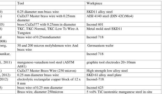
2.2 Previous research in Wire EDM
Table 2.1 until 2.6 conclude all the previous research regarding the WEDM and the
component for these experiments are all based on the previous so that the research is
not being done for the second time by duplicating the previous research.
The result from Table 2.2.2 shows the achievement by the researcher for their
experiment that is aligned with their objectives. From the Table 2.2.2, there are lots
of factors that have been affecting the results which are the parameters itself and the
combined parameters have significant and less significant effect on the response for
example Kerf width, surface roughness and etc. So, to obtain a good result based on
the objective, the most significant parameter need to be optimized.
Material, tool and workpiece used in Table 2.1 state the related material, tool and
workpiece used in their experiment. Most of them use the wire with the diameter of
0.25mm and some of them also used the Inconel 718 as the material being cut.
While, the material and wire used are different than Inconel 718, the properties of the
material in their experiment are somehow does not differ a lot than Inconel 718..
Due to the WEDM require a decent voltage and other parameters that will be later
used in the experiment, the range of parameter that will be used as shown in Table
2.3 should be within the range of the machine and the stock size of the material for
the experiment like the stock size in Table 2.2 also need to be considered. The feed
rate is chosen are based on the ability of the machine to cut one of the hard material
for example tungsten carbide. The parameter chosen are also based on the manual
book for the machine where it list all the configuration of the parameter that need to
be set up before starting the cutting process.
The Table 2.4 shows that the findings for the previous research where it can be used
to validate this experiment or vice versa. These findings are related between each
other and some researchers have been doing research in obtaining a multiple
response based on the parameter selected. Any findings from the previous one can be
The lists of machine used by the researcher are stated in Table 2.5 and the equipment
that will be used in this particular experiment is based on the availability of the
equipment itself where it can be found in Utem laboratory. The optical microscope
used are placed in the Meterology lab where it is used to measure physical properties
for example length, angle and etcetera for a fine material. The resolution of the
machine is still within the range of Kerf width so any length of Kerf width is still can
be measured when using this equipment.
The Table 2.6 shows the design of experiment (DOE) method used to analyze the
interaction and generate optimized parameter for the experiment. The statistics
software used to design for this experiment are generated by using the Design Exper t
software and it is based on the Response Surface methodology. The software
generates the possible combination of parameter and the number of required
experiment. The result of the experiment can be later used on for generating the
2.2.1 Material, tool and work piece used
Table 2.1: Material, tool and work piece used
Author Tool Workpiece
(Huang et al., 1999) 0.25 diameter mm brass wire SKD11 alloy steel (Tosun et al., 2004) CuZn37 Master brass wire with 0.25mm
diameter
AISI 4140 steel (DIN 42CrMo4)
(M.S. Hewidy, 2005) brass CuZn377 with 0.25mm in diameter Inconel 601 (Okada et al., 2008) TKC, TKC-Normal, TKC-Low Ts Wire-A
Tungsten
Metal mold steel SKD11
(Ramakrishnan and Karunamoorthy, 2008)
brass wire of 0.25mmdiameter Inconel 718
(Rakwal and Bamberg, 2009)
50 and 200 micron molybdenum wire And brass wire
Germanium wafer
(Ghewade and Nipanikar, 2011)
Inconel 718
(Gostimirovic et al., 2011) manganese-vanadium tool steel (ASTM A681)
graphite tool electrodes 20×10mm
(Gupta et al., 2012) CuZn37 Master Brass Wire (250 micron) High strength low alloy steel (Kumar and Singh, 2012) 0.25 mm diameter brass wire SKD 61 alloy steel plate (Sudhakara et al., 2012) electrolytic rectangular copper block of 12 x
8 mm
Inconel-718
(Rodge et al., 2013) brass wire of 0.25 mm diameter Inconel 625