Article
Effect of the Molten Metal Stream’s Shape on Particle
Size Distribution of Water Atomized Metal Powder
Suchart Yenwiset
aand Tawichart Yenwiset
b,*
Department of Industrial Education, Faculty of Industrial Education and Technology, Rajamangala University of Technology Srivijaya, Songkhla, Thailand
E-mail: a[email protected], b[email protected] (Corresponding author)
Abstract. The current knowledge indicated that water pressure, molten metal temperature, water flow rate and water jet configuration are very important factors which affect on the particle size distribution and shapes of atomized powder. This study aimed to investigate whether the shape of molten affects the particle size of atomized powder. The experiments were the production of copper powder with the fixed atomization process conditions, but varied the shape of molten metal by using two different shapes of tundish nozzle’s orifice to make the round and rectangular cross section of molten metal stream. There were three sizes for each orifice shape to determine the rate of production (metal flow rate) at 13 kg/min, 19 kg/min and 26 kg/min. The results showed that at the same flow rate of molten metal the production of flat metal stream from rectangular orifice made higher yield of finer particle, smaller median size (D50) and narrower range of size distribution than the production with the round cross section orifice for every production rates.
Keywords: Metal powder, water atomization, particle size distribution, tundish.
1.
Introduction
The metal powder used in the manufacturing process must have appropriate properties such as size, shape, and size distribution. Particle size is one of the most important properties to be considered, for using finer resolution powder enhances the accuracy of the work piece [1].
Atomization is one of the leading forerunners among the most promising and economic techniques for the fabrication of powders. the commonly applied mechanism for atomization involves the disintegration of liquid into a fine spray of droplets by high-velocity fluids [2].
Powder production, using an atomization process, has been being widely investigated and applied in industry [3], due to its advantages including high capacity, high flexibility for both elemental and pre-alloyed powder production and capability for rapidly solidified metal powder production. The rapidly solidified metal powders usually exhibit superior properties caused by fine microstructure, chemical homogeneity, extended solid solution and metastable phase formation. Therefore, metal parts produced from the rapidly solidified metal powders show superior mechanical properties.
In principle, when the metal melt is caused unstable by any forces it will be broken into forms of smaller pieces or droplets. Melt disintegration mechanism is shown in Fig.1 [4]
.
Fig. 1. The schematic steps involved in the “scrape” mechanism of water atomization [4].
Atomization begins with melting of metal. The liquid metal flows through a sized orifice from a tundish nozzle. Liquid flow is impinged by a high velocity stream of water. This breaks the liquid stream into particles that solidify rapidly. Particle size and shape are greatly influenced by the atomizing medium, pressure, and flow rate [5, 6].
For commercial practice of production of copper powder, liquid copper is superheated to about 1,150 to 1,200 °C, utilizing flow rates of 27 kg/min or more. Generally, to produce -100 mesh (-149 micron) copper powder, water pressure of 10 to 14 MPa (1,500 to 2,000 psi) is used. Atomization may be conducted in an air or inert (nitrogen) environment [7].The typical yield of producing -325 mesh (-44 micron) powder with atomization method is from 25 to 80 percent [8].
High Pressure water atomization can provide fine powder. With increasing atomization water pressure, the particle size tends to become finer and particle size distribution also tends to become broader [9].
German (2001) reported the result of steel powder producing using 1.7 MPa water pressure and the obtained average particle size is 117 m stating that if the water pressure is increased to 13.8 MPa, the average particle size decreases to 42 m [10].
Seki et al. (1990) found that to produce finer particle resolution of 10 m, the process must operate with higher water pressure called High-Pressure Water Atomization (HPWA) which required very high water pressure up to 70 MPa. They also presented the relationship between the average metal particle diameter and the atomization pressure for two types of water atomization process as the following equations [11]:
D = 68P-0.56forV-jet water nozzle (1)
D = 114P-0.58for cone water nozzle (2)
[image:2.595.95.497.301.364.2]Fig. 2. Type of water jet in water atomization process (a) V-jet and (b) cone jet [10].
Grandzol (1973) showed a simple relationship between the average particle size, D (µm), and the water velocity, Vw (m/s), which later modified by Grandzol and Tallmadge [12] to yield.
D = S/(Vw sin ) (3)
where is the angle between the water jet axis and the molten metal stream axis and S is the normal velocity component.
In the previous studies, Yenwiset S. and Yenwiset, T. (2010) reported that using double V-jet water atomization made resolution metal powder finer than using cone water nozzle at the same water pressure [13] and in 2011 reported that higher water pressure and higher metal’s superheat temperature made more yield of finer particles [14].
Fig. 3. Schematic of double V-jet water atomization [15].
M. Pasupathy et al. (2011) studied about the effect of the atomizer geometrical configuration on particle size and shape of atomized powder and the results showed that when impact angle is increased and/or water jet length reduced, the obtained powder becomes finer and more irregular [16].
From the information above, it is clear that to produce very fine metal powder, the process requires much energy for very high water pressure and very high superheat temperature of metal. However, besides the above variables, the shape of the molten metal stream may affect the production of metal powders as well.
[image:3.595.164.433.82.247.2] [image:3.595.246.348.409.575.2]2.
Experimental
2.1. Material
Material employed for this study was copper with 99% purity.
2.2. Variable
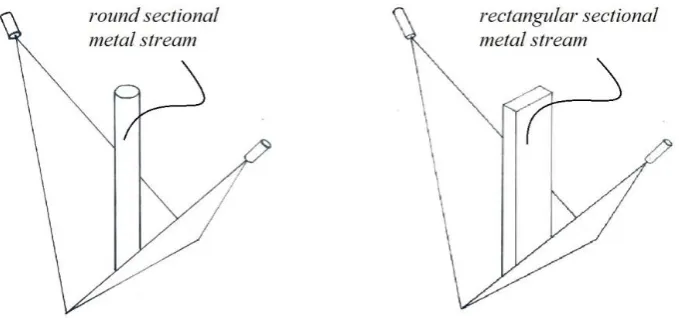
Two shape of tundish nozzle’s orifice were used in the experiments to make round sectional metal stream and flat rectangular sectional metal stream.
To emphasize at the effect of metal stream shape, the metal flow rate from the two different shapes of nozzle orifice are controlled to nearly equal by using the similar size of cross-sectional area to avoid the effect of different metal flow rate.
However, three different sizes for each shape were applied to the experiment to validate whether the metal stream shape affecting on the particle size of powder.
Fig. 4. Metal streams from round sectional orifice and rectangular sectional orifice.
Table 1. Tundish nozzle orifice’s shapes and sizes used in the experiment.
Round sectional orifice Rectangular sectional orifice Approximate metal flow
rate call
sign diameter
cross sectional
area
call
sign dimension
cross sectional
area
A1 5 mm 19.63 mm2
B1 3 mm * 6.5 mm 19.5 mm2
13 kg/min A2 6 mm 28.27 mm2
B2 3 mm * 9.5 mm 28.5 mm2
19 kg/min A3 7 mm 38.48 mm2
B3 3 mm * 12 mm 39.0 mm2
26 kg/min
2.3. Operating Conditions in Water Atomization
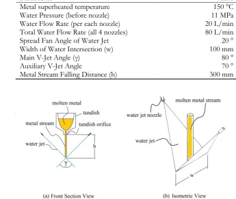
[image:4.595.127.467.283.442.2]Table 2. Water atomization process conditions.
Parameter Value
Metal superheated temperature 150 °C
Water Pressure (before nozzle) 11 MPa
Water Flow Rate (per each nozzle) 20 L/min Total Water Flow Rate (all 4 nozzles) 80 L/min
Spread Fan Angle of Water Jet 20 °
Width of Water Intersection (w) 100 mm
Main V-Jet Angle (γ) 80 °
Auxiliary V-Jet Angle 70 °
Metal Stream Falling Distance (h) 300 mm
Fig. 5. Water atomization machine’s configuration: (a) front sectional view and (b) isometric view.
2.4. Experimental Procedure
From Table 1, six different tundish orifices were applied into the experiment. Three replicates were produce with each orifice and 15 kilogram of copper was produced for each batch. Therefore, a total 45 kilogram of copper was produced for each orifice.
Fig. 6. Water atomization process: (a) using round orifice; and (b) using rectangular orifice.
3.
Results and Discussions
[image:5.595.68.529.492.639.2]Table 3. Sieved size distribution of copper powder produced at 13 kg/min metal flow rate. ASTM-E11 Sieve Designation No. Standard Size (µm)
Produced with A1 (5 mm orifice)
Produced with B1 (3 mm x 6.5 mm orifice) %
Retained Cumulative % Passing
%
Retained Cumulative % Passing
100 150 6.8 93.2 4.7 95.3
120 125 0.9 92.3 1.1 94.2
140 106 3.6 88.7 2.6 91.6
170 90 4.1 84.6 5.2 86.4
200 75 9.3 75.3 6.8 79.6
230 63 8.4 66.9 9.2 70.4
270 53 13.1 53.8 11.8 58.6
325 45 12.6 41.2 13.4 45.2
400 38 16.7 24.5 16.1 29.1
450 32 13.3 11.2 15.3 13.8
500 25 7.0 4.2 8.5 5.3
pan 0 4.2 - 5.3 -
Fig. 7. Cumulative percentage of undersize of copper powder produced with metal flow rate 13 kg/min.
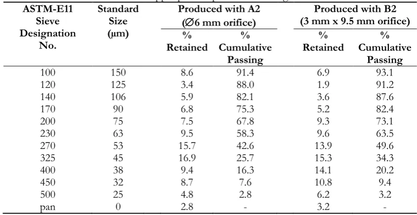
Table 4. Sieved size distribution of copper powder produced at 19 kg/min metal flow rate. ASTM-E11 Sieve Designation No. Standard Size (µm)
Produced with A2 (6 mm orifice)
Produced with B2 (3 mm x 9.5 mm orifice) %
Retained Cumulative % Passing
%
Retained Cumulative % Passing
100 150 8.6 91.4 6.9 93.1
120 125 3.4 88.0 1.9 91.2
140 106 5.9 82.1 3.6 87.6
170 90 6.8 75.3 5.2 82.4
200 75 7.5 67.8 9.3 73.1
230 63 9.5 58.3 9.6 63.5
270 53 15.7 42.6 13.9 49.6
325 45 16.9 25.7 15.3 34.3
400 38 9.4 16.3 14.1 20.2
450 32 8.7 7.6 10.8 9.4
500 25 4.8 2.8 6.2 3.2
[image:6.595.80.514.91.527.2] [image:6.595.85.507.553.771.2]Fig. 8. Cumulative percentage of undersize of copper powder produced with metal flow rate 19 kg/min.
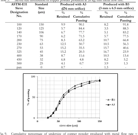
Table 5. Sieved size distribution of copper powder produced at 26 kg/min metal flow rate. ASTM-E11
Sieve Designation
No.
Standard Size (µm)
Produced with A3 (6 mm orifice)
Produced with B3 (3 mm x 6.5 mm orifice) %
Retained Cumulative % Passing
%
Retained Cumulative % Passing
100 150 9.9 90.1 8.2 91.8
120 125 5.7 84.4 3.5 88.3
140 106 6.7 77.7 5.1 83.2
170 90 6.2 71.5 5.7 77.5
200 75 8.3 63.2 10.7 66.8
230 63 12.5 50.7 10.5 56.3
270 53 15.2 35.5 15.7 40.6
325 45 15.2 20.3 16.7 23.9
400 38 8.7 11.6 10.5 13.4
450 32 6.8 4.8 8.2 5.2
500 25 4.1 0.7 3.9 1.3
[image:7.595.151.452.89.274.2] [image:7.595.72.514.321.751.2]Table 6. Comparison of the yield of the production with each orifice.
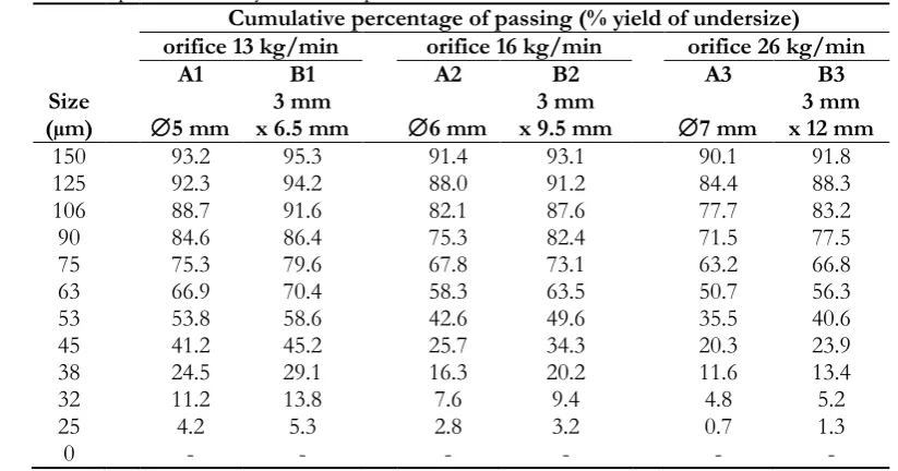
Cumulative percentage of passing (% yield of undersize) orifice 13 kg/min orifice 16 kg/min orifice 26 kg/min
A1 B1 A2 B2 A3 B3
Size
(µm) 5 mm x 6.5 mm 3 mm 6 mm x 9.5 mm 3 mm 7 mm x 12 mm 3 mm
150 93.2 95.3 91.4 93.1 90.1 91.8
125 92.3 94.2 88.0 91.2 84.4 88.3
106 88.7 91.6 82.1 87.6 77.7 83.2
90 84.6 86.4 75.3 82.4 71.5 77.5
75 75.3 79.6 67.8 73.1 63.2 66.8
63 66.9 70.4 58.3 63.5 50.7 56.3
53 53.8 58.6 42.6 49.6 35.5 40.6
45 41.2 45.2 25.7 34.3 20.3 23.9
38 24.5 29.1 16.3 20.2 11.6 13.4
32 11.2 13.8 7.6 9.4 4.8 5.2
25 4.2 5.3 2.8 3.2 0.7 1.3
0 - - - -
The most widely used indicator to describe particle size distribution are D-values. The D10, D50 and D90 are commonly used to represent the midpoint and range of the particle size [18, 19]. Particle size distribution have been traditional calculated based on sieve analysis results, creating S-curve of cumulative percentage against sieve size, and find the intercepts for 10%, 50% and 90% mass. They give an indication of the fine (D10), coarse (D90) and median (D50) particle size. The most common values used for measuring the distribution width is the range which calculated by equations below [20]:
Particle Size Distribution Range = D90 – D10 (4)
The D-values measure form the S-curves are shown in Table 7 and Fig. 10.
Table 7. The D-values and the Ranges of distribution.
Metal flow rate Produced with D10 (m)
D50 (m)
D90 (m)
Range (D90-D10)
13 kg/min A1 (5 mm) B1 (3 mm x 6.5 mm) 32 29 51 48 112 100 80 71
19 kg/min A2 (6 mm) B2 (3 mm x 9.5 mm) 34 32 58 54 140 120 106 88
[image:8.595.102.489.455.588.2]Fig. 10. Particle size distribution range from D10 to D90 with D50.
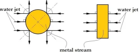
The results show that at the same metal flow rate, production with wide-thin metal stream from rectangular orifices provided narrower range of particle size distribution and smaller D50 than production with round orifices. It might explain that metal stream from rectangular orifices has wider flat area which face directly to the water jets and thinner stream which made easier to be atomized. While the outer curve of round section metal stream will not impinge perpendicular to water jets and more thickness in the middle make it be less atomized (see Fig. 11).
Fig. 11. Impinge of water jet and metal stream comparison between round and rectangular cross section metal stream.
From the yields, D50 and ranges of distribution which shown in Table 6, 7 and Fig. 10, it could be said that production with the thin flat metal stream can produce more yield of finer resolution powder at the same production rate. And because of narrower range of size distribution we can obtain more yield of any specific particle size.. On the other hand, while compare the results of A1 (13 kg/min) with B2 (19 kg/min) or A2 (19 kg/min) with B3 (26 kg/min) their D-values and range are very similar. It could be said that the production of flat metal stream can produce as similar resolution as the production of round section stream but higher production rate.
4.
Conclusions
The results indicated that the shape of molten metal stream can affect the resolution of atomized metal powder significantly. At the equally molten metal’s flow rates, the production with the flat metal stream from rectangular section orifices can make smaller size of D10, D50 and D90, narrower range of size distribution than the production using round section orifices.
[image:9.595.144.453.78.264.2] [image:9.595.186.414.383.471.2]For the same shape of molten metal orifice, producing with the smaller size of orifice or lower metal flow rate made D10, D50 and D90 tend to become smaller. That means increasing of the ratio of water/metal flow rate will made higher yield of finer particle.
At the same process conditions, using rectangular cross section orifice made higher yield of finer resolution powder than producing with the circular cross section orifice. That means the process consumed the same amount of energy but produced finer powder.
References
[1] A. Bose, “Introduction,” in Advanced in particulate Materials. MA: Butterworth-Heinemann, 1995, pp. 1–5. [2] A. Bose, “Melt atomization,” in Advanced in particulate Materials. MA: Butterworth-Heinemann, 1995, pp. 86. [3] J. J. Dunkly, “Gas atomization a review of the current state of the art,” Advances in Powder Metallurgy &
Particulate Materials, vol. 1, pp. 55–66, 1999.
[4] R. J. Grandzol, “Water atomization of 4620 steel and other metals”, Ph.D. Thesis, Dept. Chem. Eng., Drexel University, Philadephia, PA, 1973.
[5] R. W. Stevenson, “P/M copper-base alloys,” in ASM Handbook, Powder Metallurgy, 9th ed. Ohio, ASM, 1984, vol. 7, pp. 733–740.
[6] E. Klar and J. W. Fesko, “Gas and water atomization,” in ASM Handbook, Powder Metallurgy, 9th ed. Ohio, ASM, 1984, vol. 7, pp. 25–39.
[7] E. Klar, “Production of copper powder by atomization,” in ASM Handbook, Powder Metallurgy, 9th ed. Ohio, ASM, 1984, vol. 7, pp. 116–118.
[8] P. W. Taubenblat, “Importance of copper in powder metallurgy,” Int. J. Powder Met. and Powder Tech., vol. 10, no. 2, pp. 169, Jul, 1974.
[9] A. Kimura, K. Nakabayashi, and T. Shimura, “Powder production at pacific metals,” Metal Powder Report, vol. 45, no. 2, pp. 106–110, Feb, 1990.
[10] R. M. German, Powder Metallurgy Science. Princeton, NJ: MPIF, 1984, pp. 80.
[11] Y. Seki, S. Okamoto, H. Takisawa, and N. Kawai, “Effect of atomization variables on powder characteristics in the high-pressured water atomization process,” Metal Powder Report, vol. 45, no. 1, pp. 38–40, Jan, 1990.
[12] R. J. Grandzol and J. A. Tallmadge, “Effect of jet angle on water atomization,” Int. J. Powder Met. and Powder Tech., vol. 11, pp. 103–114, 1975.
[13] S. Yenwiset and T. Yenwiset, “Design and construction of water atomizer for making metal powder,” Journal of Metals,Materials and Minerals, vol. 21, no. 1, pp. 75–81, Jun, 2011.
[14] S. Yenwiset and T. Yenwiset, “Study on key variables that influence the effectiveness of water atomization process,” in Proceedings of EURO PM 2011 Powder Metallurgy Congress and Exhibition, Barcelona, Spain, Sep., 2011, vol. 2, pp. 43–48.
[15] J. M. Vetter, G. Gross, and H. W. Bergmann, “Production of metal powders by atomizing their melts with liquid gases,” Metal Powder Report, vol. 45, no. 2, pp. 100–104, 1990.
[16] M. Pasupathy, J. M. Martin, I. Iturriza, and F. Castro, “Effect of the atomizer geometrical configuration on the particle size and shape of water atomized powders,” in Proceedings of EURO PM 2011 Powder Metallurgy Congress and Exhibition, Barcelona, Spain, Sep., 2011, vol. 2, pp. 9–14.
[17] W. J. Ullrish, “Sieve analysis” in ASM Handbook, Powder Metallurgy, vol. 7, 9th ed. Ohio: ASM, 1984, pp. 214–216.
[18] B. B. Weiner. (2011). What is a Continuous Particle Size Distribution. Brookhaven Instruments. [Online]. Available: https://www.brookhaveninstruments.com/pdf/theory/What is a Continuous Particle Size Distribution.pdf
[19] B. B. Weiner. (2011). What is a Discrete Particle Size Distribution. Brookhaven Instruments. [Online]. Available: http://www.brookhaveninstruments.com/pdf/theory/What is a Discrete Particle Size Distribution.pdf
![Fig. 1. The schematic steps involved in the “scrape” mechanism of water atomization [4]](https://thumb-us.123doks.com/thumbv2/123dok_us/8109392.235926/2.595.95.497.301.364/fig-schematic-steps-involved-scrape-mechanism-water-atomization.webp)
![Fig. 3. Schematic of double V-jet water atomization [15].](https://thumb-us.123doks.com/thumbv2/123dok_us/8109392.235926/3.595.246.348.409.575/fig-schematic-double-v-jet-water-atomization.webp)