UNIVERSITI TEKNIKAL MALAYSIA MELAKA
Development of Sorting System Based on Colour Segregation Using
Programmable Logic Controller (PLC)
This report is submitted in accordance with the requirement of the Universiti Teknikal Malaysia Melaka (UTeM) for the Bachelor of Electronics Engineering
Technology (Industrial Electronics) with Honours
by
ONG EE WONG B071410208 940228-07-5114
UNIVERSITI TEKNIKAL MALAYSIA MELAKA
BORANG PENGESAHAN STATUS LAPORAN PROJEK SARJANA MUDA
TAJUK: Development of Sorting System Based on Colour Segregation Using
Programmable Logic Controller (PLC)
SESI PENGAJIAN: 2017/18 Semester 1
Saya ONG EE WONG
mengaku membenarkan Laporan PSM ini disimpan di Perpustakaan Universiti Teknikal Malaysia Melaka (UTeM) dengan syarat-syarat kegunaan seperti berikut:
1. Laporan PSM adalah hak milik Universiti Teknikal Malaysia Melaka dan penulis. 2. Perpustakaan Universiti Teknikal Malaysia Melaka dibenarkan membuat salinan
untuk tujuan pengajian sahaja dengan izin penulis.
3. Perpustakaan dibenarkan membuat salinan laporan PSM ini sebagai bahan pertukaran antara institusi pengajian tinggi.
4. **Sila tandakan ( )
SULIT
TERHAD
TIDAK TERHAD
(Mengandungi maklumat yang berdarjah keselamatan atau kepentingan Malaysia sebagaimana yang termaktub dalam AKTA RAHSIA RASMI 1972)
(Mengandungi maklumat TERHAD yang telah ditentukan oleh organisasi/badan di mana penyelidikan dijalankan)
Disahkan oleh:
________________________
Alamat Tetap:
20A-2-3, Persiaran Mayang Pasir 5,
11950 Bukit Gedung,
Pulau Pinang.
Tarikh: ________________________
** Jika Laporan PSM ini SULIT atau TERHAD, sila lampirkan surat daripada pihak berkuasa/organisasi berkenaan dengan menyatakan sekali sebab dan tempoh laporan PSM ini perlu dikelaskan sebagai SULIT atau TERHAD.
_________________________
Cop Rasmi:
DECLARATION
I hereby, declared this report entitled “PSM Title” is the results of my own research except as cited in references.
Signature : ……….……...………...
Author’s Name : ………...
APPROVAL
This report is submitted to the Faculty of Engineering Technology of UTeM as a partial fulfilment of the requirements for the degree of Bachelor of Electronics Engineering Technology (Industrial Electronics) with Honours. The member of the supervisory is as follow:
i
ABSTRAK
ii
ABSTRACT
iii
DEDICATIONS
To my parents,
All my lectures, especially, Mr. Ir. Nik Azran Bin Ab. Hadi All my friends and relatives
iv
ACKNOWLEDGMENT
First, I would like to express my appreciation to my supervisor, Mr. Ir. Nik Azran Bin Ab. Hadi which gives a lots of advices and guidances to complete this final year project. Besides that, he also pointed my project to the correct path for development. He also helps me set the mile stone in order to make sure my project finish on time.
Next, I would like to thanks for the staffs and members of Universiti Teknikal Malaysia Melaka and also all my labmates who guide me in various perspectives throughout the project. I like to appreciate their ideas and comments that were significant for the effective accomplishment of this final year project.
v
TABLE OF CONTENT
Abstrak i
Abstract ii
Dedication iii
Acknowledgement iv
Table of Content v
List of Tables viii
List of Figures ix
List Abbreviations, Symbols and Nomenclatures x
CHAPTER 1: INTRODUCTION 1
1.0 Introduction 1
1.1 Project Background 1
1.2 Problem Statement 3
1.3 Objectives 4
1.4 Scope of Work 4
1.5 Report Structure 5
CHAPTER 2: LITERATURE REVIEW 6
2.0 Introduction 6
2.1 Existing Project for Sorting System 6
2.1.1 Development of an automated colour sorting system for 6
recycle glass containers
2.1.2 Design and development of colour sorting robot 8 2.1.3 Lego bricks colour sorting machine 9
2.1.4 Smart colour sorting robot 10
2.1.5 Automatic colour sorting machine using TCS230 and PIC 11 2.1.6 Development of an automatic colour sorting machine on 12
belt conveyor
vi 2.1.9 Intelligent fruit sorting system using colour image processing 14 2.1.10 Automatic sorting machine using conveyor belt 14
2.2 Software Review 15
2.2.1 Programmable Logic Controller (PLC) 15
2.3 Component Review 16
2.3.1 DC Motor 16
2.3.2 Light dependent resistor (LDR) 17
2.3.3 Super ultra-bright white LED 19
CHAPTER 3: METHODOLOGY 20
3.0 Introduction 20
3.1 Project Methodology 21
3.2 Project Planning 23
3.2.1 Searching for project title 23
3.2.2 Analysis the colour sensor circuit operation 23
3.2.3 Proposal preparation 23
3.2.4 Searching information on the components 24
3.2.5 Simulation on circuit 24
3.3 Flow Process of Project 25
3.3.1 Report Work Flow 25
3.3.2 Main Flowchart 26
3.3.3 Project Work Flow 27
3.4 Project Consideration 29
3.5 Software 30
3.5.1 Proteus 30
3.5.3 CX-Supervisor 30
3.5.4 CX-Programmer 31
3.6 Printed Circuit Board (PCB) Process 32
3.6.1 Circuit Printing 32
3.6.2 UV Curing 32
3.6.3 PCB Developer 33
3.6.4 Etching Process 33
vii
3.6.6 Cutting 34
CHAPTER 4: RESULT AND DISCUSSION 35
4.0 Introduction 35
4.1 Result 35
4.1.1 Output Voltage Sensed on Different Colour 35
4.1.2 Indoor and Outdoor Tests 36
4.1.3 Non-amplified and Amplified Output Voltage 37
4.1.4 Calculation 38
4.2 Basic concept of sorting system 42
4.3 Data Analysis and Discussion 44
4.4 Comparison between Manual Sorting with Project Design 47
CHAPTER 5: CONCLUSION & FUTURE WORK 48
5.0 Introduction 48
5.1 Conclusion 48
5.2 Future Work 49
REFERENCES 50
APPENDICES
A Colour sensor
B SCADA
C Grafcet
viii
LIST OF TABLES
2.1 RGB filter during indoor test 9
2.2 RGB filter during outdoor test 9
2.3 Description on super ultra-bright white LED 19
3.1 Gantt chart 22
3.2 Project consideration hardware 29
4.1 Output voltage on colour 35
4.2 Output voltage during indoor and outdoor 36
4.3 Output voltage on cover and non-cover 37
4.4 Output voltage readings before amplified 37
4.5 Amplified output voltage readings 37
4.6 Hexadecimal on output voltage 40
4.7 Coefficient of variation on red colouring box 40 4.8 Average, standard deviation and coefficient of variation 41
4.9 Activation of pilot lamp 43
ix
LIST OF FIGURES
1.1 Entire process flow 2
1.2 Automatic sorting hardware design 4
2.1 Recyclable glass containers sorting prototype 7
2.2 System Overview 8
2.3 Colour sorting robot product design 9
2.4 Block diagram of the grading system 10
2.5 Colour sorting robot project sequence 11
2.6 Automatic colour sorting machine using PIC 12
2.7 Block diagram of motion control 13
2.8 Hardware flow of arm sorting robot 14
2.9 Hardware design using conveyor belt 15
2.10 PLC operation 16
2.11 DC motor construction 17
2.12 A graph of relationship between LDR resistance and light intensity 18
3.1 Block diagram of sorting system 20
3.2 Flowchart of the report work 25
3.3 Flowchart of project work 26
3.4 Flowchart for sorting system 28
3.5 Function in the main window 31
3.6 Accublack paper 32
3.7 Developer machine 33
3.8 Etcher machine 34
4.1 A graph of output voltage against different colour 36 4.2 A graph of output volage for indoor and outdoor tests 36 4.3 A graph of average output voltage against colour 38
4.4 Time chart 41
x
LIST OF ABBREVIATIONS, SYMBOLS AND
NOMENCLATURE
A/D - Analog to Digital AC - Alternating Current
ADC - Analog to Digital Converter AREF - Analog Reference
AVR - Advanced Virtual RISC BLDC - Brushless DC
C - Celcius
CCP - Capture/Compare/PWM
CH - Channel
cm - Centimeter
CMOS - Complementary Metal-Oxide Semiconductor DC - Direct Current
FPGA - Field Programmable Gate Array GUI - Graphical User Interface
I/O - Input Output
IDE - Integrated Development Environment
IR - Infrared
kΩ - Kilo ohm
KB - Kilobyte
LCD - Liquid-Cystal Display LD - Ladder Diagram
LDR - Light Dependent Resistor LED - Light Emitting Diode
m - Meter
xi PC - Personal Computer
PCB - Printed Circuit Board
PLC - Programming Logic Controller PIC - Peripheral Interface Controller PWM - Pulse-Width Modulation
RISC - Reduced Instruction Set Computing
RX - Receive
TX - Transmit
USB - Universal Serial Bus
1
CHAPTER 1
INTRODUCTION
1.0 Introduction
Nowadays, the capacity to differentiate colour is crucial for human’s life as it gives us the awareness surrounding through eyesight. Hence, colour is one of the most important features for accurate classification in the sorting system. Since 1990s, the sorting system in production lines for the food processing industries such as coffee, nuts and oil crops was performed manually (Sujata and Dr. Padole, 2014). However, the manual inspection is slow and inconsistent. This is because employee who has been performing the repeating manual inspection task may fail to recognize the colour of product due to fatigue of long term working hour without rest. In 1895, Taylor proposed an automatic bruise detection system. With the aid of colour capture, an automatic colour sorting system able to differentiate, sort and organize. The sorting system mostly used to ensure quality can be up to mark. The process can be progressed by using mechanical or pneumatic ejection (Sujata and Dr. Padole, 2014).
1.1 Project Background
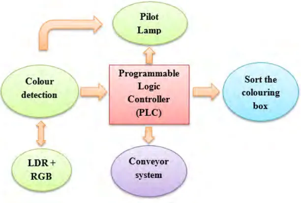
2 The colour sensor senses the colouring box by using the Programmable Logic Controller (PLC) which acts as a main controller for the sorting system. The conveyor which is controlled by the PLC will bring the box that sensed by both Light Dependent Resistor (LDR) sensor and 4 super ultra brightness LED to the exact location. The circuit that consists of LDR sensor and super ultra brightness LED is able to determine the light intensity level on the box.
The colour sensor and pneumatic cylinders are also programmed by PLC. Pilot lamp will turn on after read the information which transmitted by the colour sensor. In this sorting system, there are four pilot lamp which used to indicate different colour. The indicator for the sensed colour for each pilot lamp are shown below:
Green Pilot Lamp 1 = White Green Pilot Lamp 2 = Blue
Red Pilot Lamp = Red Yellow Pilot Lamp = Black
[image:17.595.184.490.509.715.2]This colour sorting system has marketing purpose due to low cost, increment productivity and reduction human resources. Figure 1.1 shows the entire process flow of this project.
3
1.2 Problem Statement
There are some issues that often happen in the industry that can be cleared out by using this project are:
i. The limitation of time response for human eye caused the colour sorting process by a worker is very slow. Besides, mostly operator will feel tired after a long day working. It will cause the operator unable to perform well as usual and lower down the performance for an operator. However, this limitation can be avoided by using an automatic system that can reduce the time spent for the sorting process. The automatic sorting system will maintain the same speed during sorting process.
ii. Worker usually make mistakes easily during the colour sorting process can affect the productivity of the company. This is because an operator needs to handle thousand of products each day caused them feel sleepy and tired. Hence, it is common if operator makes a mistake. By using the automatic sorting system, the operators just have to operate the system which gives accurate result even it has been repeated for billions of times.
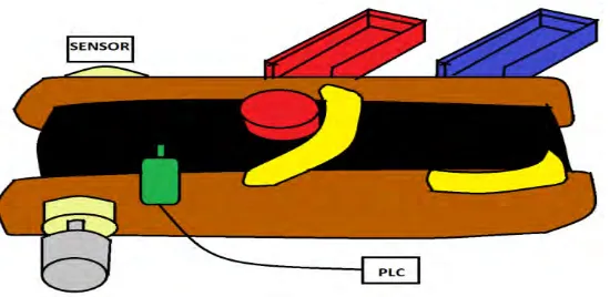
4 Figure 1.2: Automatic sorting hardware design
1.3 Objectives
The intention of this project is to create a sorting system which can achieve the following objectives:
i. To make sure that the sorting system runs continuously with less rest. ii. To eliminate the human error during sorting process.
iii. To design and develop a low cost colour sorting system using Programmable Logic Controller (PLC).
1.4 Scope of Work
This work requires a few scopes and guidelines to assure that this project able to conduct around the expected borderline and right direction for achieving those objectives. Hence, the project work scope are as below:
i. Research and study on the Light Dependent Resistor for colour sensor.
ii. Research and study on Programmable Logic Controller.
iii. To design circuitry for the overall system.
5
1.5 Report Structure
Five chapters are combined in this report which are introduction, literature review, methodology, result & discussion and conclusion & recommendation of the project.
Chapter 1 is an introduction for the whole project. This chapter will briefly explain the background of sorting system and important objectives of the project. Besides that, the problem statement and scope of the project are also added in this topic.
Chapter 2 compiles the literature review, generally on the existing projects and components that used in this project. This part concentrates on the theory of all aspects of the sorting system. Sources from journals, books, thesis and website that covering all the information connected to the project are included.
Chapter 3 is about the methodology of the project which shows steps and flow for the problem solving in designing the interface of the project to combine with Programmable Logic Controller (PLC). This part concentrates on the procedure to execute the project from the primary design until the end. Strategy and time management are presented in this part. The project’s gantt chart also added here.
Chapter 4 describes the expected result from this project and ensures the objectives of the project is achieved.
6
CHAPTER 2
LITERATURE REVIEW
2.0 Introduction
Chapter 2 is to review some fundamental ideas from the research. It is necessary to study on journal that related to the project because knowledge and skills needed to complete the project. In other word, this chapter is the brief or idea on published journal that similar as this project. All the components using for this project will discuss in this chapter as well.
2.1 Existing Project for Sorting System
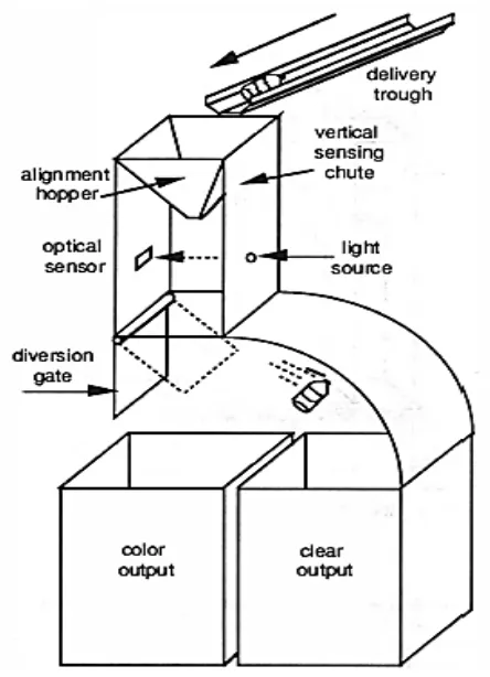
2.1.1 Development of an automated colour sorting system for recycle glass containers
7 three purposes: (a) vertical alignment of the bottles; (b) put the bottles at centre so that pass through the light beam; (c) speed reduction of the bottles to facilitate a longer sensor reading. After pass through light beam and light transmittance is sensed and passed to control circuits. A high intensity light emitting diode (LED) with a luminous intensity 500 mcd functions as the light source. The optical sensor used as input data for computer coded mathematical model of control circuit. After sensed by the sensor, the diversion gate will control the degree of opening gate to sort the glass container accurately. For the automated and manual sorting, this project achieved 100% success rate and 70% rate at 1.25 ton/hr/chute. According to Lewis and Newell (1991), they recommended that the colour sorting should occur near to the generator to increase the handling process. For this project, cost and success rate are the critical factors in evaluating the colour sorting system (Lewis and Newell, 1991).
8
2.1.2 Design and development of colour sorting robot
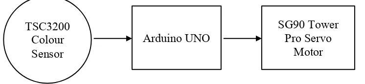
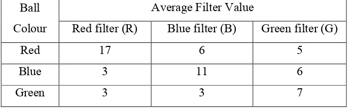
[image:23.595.156.529.360.446.2]This paper shows a colour sorting robot is designed using the colour processing via Arduino UNO. The programming code enable the system to array the colour ball using the colour sensor in minimum time. The components used are microcontroller, TCS3200D colour sensor, servo motor and other basic electronic components. The method for TCS 3200D to determine the colour is by using the RGB filters and compare the value that reflected on it. The RGB values checked by using Adobe Photoshop software. Irda and Lim (2015) shows the system overview on the highest value in colour filter send to Arduino. Arduino UNO receives the analog signal from the sensor that detects the colour of the object and triggers the slider at servo motor to move different angle of 10°, 70° or 170° depending on the colour sensed.
Figure 2.2: System overview (Irda and Lim 2015)
The colour stations are classify into red, green and blue. After placed the ball, the slider return back to original position to await the colour ball. For this project, the collected data analysis includes the light intensity test and colour ball selection test. Table 2.1 and Table 2.2 shows that RGB values taken indoor are greater than outdoor due to more than single light at outdoor (Irda and Lim 2015). Irda and Lim (2015) also mentioned that the Arduino-powered sorting robot is more profitable compared to the current sorting system. They also recommended that the RGB values should be display on the Arduino Serial Monitoring Screen to benefit people to intend to observe. Figure 2.3 (Irda and Lim 2015) captures the robot hardware design.
TSC3200 Colour
Sensor Arduino UNO
SG90 Tower Pro Servo
9 Table 2.1: RGB filter during indoor test (Irda and Lim 2015)
Ball Colour
Average Filter Value
Red filter (R) Blue filter (B) Green filter (G)
Red 17 6 5
Blue 3 11 6
[image:24.595.160.504.274.381.2]Green 3 3 7
Table 2.2: RGB filter during outdoor test (Irda and Lim 2015)
Ball Colour
Average Filter Value
Red filter (R) Blue filter (B) Green filter (G)
Red 18 16 9
Blue 7 12 10
[image:24.595.219.456.405.555.2]Green 2 5 6
Figure 2.3: Colour sorting robot product design (Irda and Lim, 2015)
2.1.3 Lego bricks colour sorting machine