i
ABSTRACT
ii
ABSTRAK
iii
DEDICATIO
Dedicated to my father, Mohamad Fazee bin Abd Aziz and my mother, Zilis Binti Mohamad.
I would like to convey my appreciation and indebtedness to those who
great surprised and helpful for the completion at the project to bring it to success in respect with favorable advice and feasible solution
Thus, I feed comfortably to take this golden opportunity to express my millions of gratitude to my supervisor, Mr Abd Halim Hakim Bin Abd Aziz for his kindly advice and guidance during the project providing tremendous considerately and useful comment and materials to overcome each obstacle I had faced.
Also special thanks to my friends that give me some help d
Thanks extended to FKP lecturer who had provided technical help and assistance throughout the project.
Lastly I would like to thank my family, who has been the loveliest advisor to give continually support and inspiration through
genial thanks to everyone I have not mentioned above from bottom of my heart
iv
ACKOWLEDGEMETS
I would like to convey my appreciation and indebtedness to those who
great surprised and helpful for the completion at the project to bring it to success in respect with favorable advice and feasible solution
Thus, I feed comfortably to take this golden opportunity to express my millions of sor, Mr Abd Halim Hakim Bin Abd Aziz for his kindly advice and guidance during the project providing tremendous considerately and useful comment and materials to overcome each obstacle I had faced.
Also special thanks to my friends that give me some help during doing this project. Thanks extended to FKP lecturer who had provided technical help and assistance throughout
Lastly I would like to thank my family, who has been the loveliest advisor to give continually support and inspiration throughout my campus life. With this my sincere and genial thanks to everyone I have not mentioned above from bottom of my heart
I would like to convey my appreciation and indebtedness to those who has-been great surprised and helpful for the completion at the project to bring it to success in respect
Thus, I feed comfortably to take this golden opportunity to express my millions of sor, Mr Abd Halim Hakim Bin Abd Aziz for his kindly advice and guidance during the project providing tremendous considerately and useful comment and
uring doing this project. Thanks extended to FKP lecturer who had provided technical help and assistance throughout
v
TABLE OF COTETS
Abstract i
Abstrak ii
Dedication iii
Acknowledgement iv
Table of Content v
List of Figure x
List of Table xiii
List of Abbreviation xv
1. ITRODUCTIO 1
1.1 Project Background 1
1.2 Problem Statement 8
1.3 Objectives 8
1.4 Scope of project 9
2. LITERATURE REVIEW 10
2.1 Introduction 10
2.2 What is Drain Cover? 11
vi
2.2.1.1 Stiffness 12
2.2.1.2 Strength 13
2.2.1.3 FRP versus HDPE 14
2.2.3 Material Design and Engineering 15
2.2.4 Material Modulus of Elasticity 15
2.3 Material Properties 16
2.4 FEA Solution and Output Data 18
2.5 The Average of vehicle Weight 22
2.6 Product Planning Process 23
2.6.1 Identify Opportunities 24
2.7 Identify Customer Needs 26
2.7.1 Customer Satisfaction 27
2.8 Quality Function Deployment (QFD) 28
2.8.1 QFD Overview 29
2.9 Computer Aided Design 30
2.9.1 Element of CAD System 31
2.9.2 CAD software (SolidWorks) 32
2.9.3 3D computer graphics 32
2.11 Finite Element Tool 33
vii
2.11.2 How does finite element analysis work? 37
2.11.3 Finite element analysis 39
2.11.4 Processing 39
2.11.5 Analysis (computation of solution) 40
2.11.6 Visualization 40
2.11.7 Application of FEA to the mechanical engineering industry 40 2.11.8 Computer Aided Design and Finite Element Analysis in industries 41
2.11.9 The advantage of FEA 43
3. METHODOLOGY 44
3.1 Introduction 44
3.2 Flow Chart 45
3.3 Phase of Methodology 48
3.3.1 Planning Phase 48
3.3.2 Design Phase 48
3.3.3 Analyze phase 49
3.3.4 Redesign and Optimize Design and Analysis Phase. 49 3.3.5 Preparation of Final Report and Presentation 50
3.4 Conceptual Design 51
3.4.1 Design 1 51
viii
3.4.3 Design 3 53
3.4.4 Design 4 54
3.4.5 Design 5 55
3.4.6 Design 6 56
3.8 Data for Drain Cover Analysis 57
3.6 Material Properties 58
Ghant Chart for PSM 1 59
Ghant Chart for PSM II 60
4. RESULT AD DISCUSSIO 62
4.1 Introduction 62
4.2 Result and Discussion 63
4.2.1 Analysis Design 1 63
4.2.2 Analysis design 2 66
4.2.3 Analysis design 3 69
4.2.4 Analysis design 4 72
4.2.5 Analysis design 5 75
4.2.6 Analysis design 6 78
ix
4.4.1 New design 83
4.4.1.1 Analysis new design 84
4.4.2 Redesign 1 88
4.4.2.1 Analysis redesigns 1 89
4.4.3 Redesign 2 93
4.4.3.1 Analysis Redesigns 2 94
4.4.4 Redesign 3 98
4.4.4.1 Analysis Redesigns 3 99
4.4.5 Redesign 4 103
4.4.5.1 Analysis Redesigns 4 105
4.4.6 Final design 109
4.4.6.1 Analysis final design 109
4.4.6.2 Analysis Final Design 111
5. COCLUSIO 116
5.1 Conclusion 116
5.2 Recommendation 117
REFERECES 119
x
LIST OF FIGURES
1. Figure 1.0: Stages in the design process
2. Figure 1.1: Step Involved in the use of Finite Element Method for solving a physical problem.
3. Figure2.1: Drain cover on the main street
4. Figure 2.2: Degree of freedoms of a simple plane beam element 5. Figure 2.3: Product research planning sequence
6. Figure 2.4: A typical House of Quality matrix
7. Figure 2.5: An Example of Finite Element Analysis Process 8. Figure 3.1: Flow Chart for Full project of PSM
9. Figure 3.2: Flow chart for PSM 1 10.Figure 3.3: The Isometric of Design 1 11.Figure 3.4: The isometric of Design 2 12.Figure 3.5: The Isometric of Design 3 13.Figure 3.6: The Isometric of Design 4 14.Figure 3.7: The Isometric of Design 5 15.Figure 3.8: The Isometric of Design 6 16.Figure 3.9: Table of type of car 17.Figure 3.10: Table of vehicle weight
18.Figure 3.11: Material Properties for Finite Element Model 19.Figure 4.1: design 1 analysis restrain
20.Figure 4.2: Design 1 Distributed load
21.Figure 4.3: Design 1 Stress distribution in model
22.Figure 4.4: Design 1 displacement distribution in model 23.Figure 4.5: Design 2 analysis restrain
xi
25.Figure 4.7: Design 2 Stress distribution in model
26.Figure 4.8: Design 2 displacement distribution in model 27.Figure 4.9: design 3 analysis restrain
28.Figure 4.10: Design 3 Distributed load
29.Figure 4.11: Design 3 Stress distribution in model
30.Figure 4.12: Design 3 displacement distribution in model 31.Figure 4.13: design 4 analysis restrain
32.Figure 4.14: Design 4 Distributed load
33.Figure 4.15: Design 4 Stress distribution in model
34.Figure 4.16: Design 4 displacement distribution in model 35.Figure 4.17: design 5 analysis restrain
36.Figure 4.18: Design 5 Distributed load
37.Figure 4.19: Design 5 Stress distribution in model
38.Figure 4.20: Design 5 displacement distribution in model 39.Figure 4.21: design 6 analysis restrain
40.Figure 4.22: Design 6 Distributed load
41.Figure 4.23: Design 6 Stress distribution in model
42.Figure 4.24: Design 6 displacement distribution in model 43.Figure 4.25: Bottom view of Drain cover new design 44.Figure 4.26: New design analysis restrain
45.Figure 4.27: New design Distributed load
46.Figure 4.28: New design Stress distribution in model
47.Figure 4.29: New design displacement distribution in model 48.Figure 4.30: Isometric view of Redesign 1
49.Figure 4.31: Redesign 1 analysis restrain 50.Figure 4.32: Redesign 1 Distributed load
51.Figure 4.33: Redesign 1 Stress distribution in model
52.Figure 4.34: Redesign 1 displacement distribution in model 53.Figure 4.35: Isometric view of Redesign 2
xii
56.Figure 4.38: Redesign 2 Stress distribution in model
57.Figure 4.39: Redesign 2 displacement distribution in model 58.Figure 4.40: Isometric view of Redesign 3
59.Figure 4.41: Redesign 3 analysis restrain 60.Figure 4.42: Redesign 3 Distributed load
61.Figure 4.43: Redesign 3 Stress distribution in model
62.Figure 4.44: Redesign 3 displacement distribution in model 63.Figure 4.45: Isometric view of Redesign 4
64.Figure 4.46: The sectional of Redesign 4 I-beam design (label 4) 65.Figure 4.47: The sectional of Redesign 4 Transverse bar (label 5) 66.Figure 4.48: Redesign 4 analysis restrain
67.Figure 4.49: Redesign 4 Distributed load
68.Figure 4.50: Redesign 4 Stress distribution in model
69.Figure 4.51: Redesign 4 displacement distribution in model 70.Figure 4.52: Isometric view of Final design
71.Figure 4.53: The sectional of Final design I-beam design (label 6) 72.Figure 4.54: The sectional of Final design Transverse bar (label 7) 73.Figure 4.55: Final design analysis restrain
74.Figure 4.56: Final design Distributed load
75.Figure 4.57: Final design Stress distribution in model
xiii
LIST OF TABLES
1. Table 2.1: The strength of FRP and HDPE 2. Table 2.2: Table of load
3. Table 3.1: Table of the FRP material properties
4. Table 3.2: FRP mechanical characteristic material properties 5. Table 4.1: Design 1 Analysis Data
6. Table 4.2: Design 2 Analysis Data 7. Table 4.3: Design 3 Analysis Data 8. Table 4.4: Design 4 Analysis Data 9. Table 4.5: Design 5 Analysis Data 10.Table 4.6: Design 6 Analysis Data
11.Table 4.7: Differentiate between 6’s designs from von Mises Stress 12.Table 4.8: Differentiate between 6’s designs from Resultant Displacement 13.Table 4.9: Guideline Result Analysis for New Drain Covers design
14.Table 4.10: New design Analysis Data
15.Table 4.11: The comparison between Guideline and New design 16.Table 4.12: Redesign 1 Analysis Data
17.Table 4.13: The comparison between Guideline and Redesign 1 18.Table 4.14: Redesign 2 Analysis Data
19.Table 4.15: The comparison between Guideline and Redesign 2 20.Table 4.16: Redesign 3 Analysis Data
21.Table 4.17: The comparison between Guideline and Redesign 3 22.Table 4.18: Redesign 4 Analysis Data
xiv
xv
LIST OF ABBREVIATIOS, SYMBOLS & OMECLATURE
CAD Computer Aided Design
FEA Finite Element Analysis FRP Fiber Reinforest glass HDPE high-density polyethylene QFD Quality Function Deployment
CAE Computer Aided Design Engineering IGES CATIA File format
STEP CATIA File format
1
CHAPTER 1
ITRODUCTIO
1.1 Project Background
Today computer is one of the most important equipment in design and manufacturing
industry. It is also gave an impact more in the industrial sector. Computer is used for
various activities in the industries. However in manufacturing industries it made a very
substantial change in their working. The computer does not only used to simplify many
of the traditional manufacturing tasks but also made it almost impossible for
manufacturing industries to survive in the modern ere without it. Thus it is important for
everyone concerned with the manufacturing industries to learn the use of computer
among the usages of computer in manufacturing, Computer aided design and Computer
aided manufacturing (CAD/CAM) are by far the best known as well as the best
application. In order to remain competitive in the global economy, it is imperative that
all manufacturing industries adopt CAD/CAM.
In the earlier days of CAD/CAM development the cost used to be prohibitive and did
not allow the small and medium scale industries to adopt it. However, this has changed
since the invention of the microprocessor and the rapid developments taking place in the
very large scale integration (VLSI) of the electronic circuit. The cost of computing
equipment in the present stage is relatively low, and this allowed the devolvement of
large for these powerful computers. The mass manufacture techniques employed for the
2
medium scale companies to use the powerful computers in their day to day operations.
Along with the developments in the hardware, the software, too, continued to develop at
a similar pace. The present day software is easier to use and very powerful, thereby
guaranteeing the result in a much shorter time than was possible earlier. This has
prompted the small and medium scale to enterprises to embrace CAD/CAM in a big way
in the development world. It is, therefore, not uncommon to see even small companies
using CAD or CAM in to improve their productivity.
CAD/CAM is related to the design where design is an activity which needs to be well
organized and takes into account all influence that are likely to be responsible for the
success of the product under development. A product here means single components,
which is functional in itself like a wrench or an assembly of large number of part or
component all of which will contribute to he functioning of the part such as an
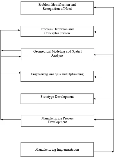
automobile engine. In design, it has stages of the design process. The flow of design
3
Figure 1.0: Stages in the design process Manufacturing Process
Development
Manufacturing Implementation Geometrical Modeling and Spatial
Analysis
Problem Identification and Recognition of Need
Prototype Development Problem Definition and
Conceptualization
4
To design, CAD technology is used. CAD or computer aided design is the use of
computer method to develop the geometric model of the product in the three
dimensional form, such that the geometric and manufacturing requirements can be
examined. Many type of cad software can be use such as SOLIDWORK, CATIA,
INVENTER and other. CATIA software is CAD/CAM family software but it one of the
best CAD software and that suitable for this project. CAD technology is used because
CAD technology can provide the necessary help in the following below:
1. Computer Aided Design (CAD) is faster and more accurate than the
conventional method.
2. The various construction facilities available in CAD would make the job of
developing the model and associated drafting a very easy task.
3. In contrast with the traditional drawing method, under CAD it is possible to
manipulate various dimensions, attributes and distances of the drawing element.
This quality makes CAD useful for design work.
4. Under CAD work will never have to repeat the design or drawing of any
component. Once a component has been made, It can be copied in all further
works within seconds including any geometric transformation need.
5. Modification of a model is very easy and would make the designers task of
improving a given product simple to take care of any future requirement.
6. Use of standard component makes for very fast model development work.
Then for the next process after product design is do an analysis of the product. Where it
is used finite element analysis as a tools. The finite element analysis (FEA) is a very
powerful analysis tool, which can be applied to a range of engineering problem. The
finite element modeling process allowed for discrediting the intricate geometries into
small fundamental volumes called finite element. It is then possible to write the
governing equations and material properties for these elements. These equations are then
5
complex body being analyzed. Application of FEA is no limited to mechanical system
alone but to range of engineering problem such as stress analysis, dynamic analysis, and
deformation studies fluid flow analysis, heat flow analysis and other.
With the FEA software it is possible to try a number of alternative designs before
actually going for a prototype manufacture. The use of FEA tools can converting the
geometry into discretised element and calculating various properties for each element
such as geometry, material properties, constraint and loading. This forms the input for
the analysis. It also can generating the finite element mesh by making a suitable
approximation to the geometry. Then it can calculate the nodes and element properties
and allowed the material properties to be specified.Under FEA it has steps involved in
the use of finite element method for solving a physical problem. The software used for