i
UNIVERSITI TEKNIKAL MALAYSIA MELAKA
STUDY OF ENGINE PERFORMANCE EFFECT USING
VARIABLE AIR FILTER ON PERODUA VIVA 1.0 ENGINE
This report submitted in accordance with requirement of the Universiti Teknikal Malaysia Melaka (UTeM) for the Bachelor Degree of Mechanical Engineering
Technology
(Automotive Technology) (Hons.)
by
AHMAD SYAUQI HAIKAL BIN HARUN B071310298
910708-10-6023
UNIVERSITI TEKNIKAL MALAYSIA MELAKA
BORANG PENGESAHAN STATUS LAPORAN PROJEK SARJANA MUDA
TAJUK: Study of Engine Perfromance Effect Using Variable Air Filter on Perodua Viva 1.0 Engine
SESI PENGAJIAN: 2016/17 Semester 1
Saya AHMAD SYAUQI HAIKAL BIN HARUN
mengaku membenarkan Laporan PSM ini disimpan di Perpustakaan Universiti Teknikal Malaysia Melaka (UTeM) dengan syarat-syarat kegunaan seperti berikut:
1. Laporan PSM adalah hak milik Universiti Teknikal Malaysia Melaka dan penulis. 2. Perpustakaan Universiti Teknikal Malaysia Melaka dibenarkan membuat salinan
untuk tujuan pengajian sahaja dengan izin penulis.
3. Perpustakaan dibenarkan membuat salinan laporan PSM ini sebagai bahan pertukaran antara institusi pengajian tinggi.
4. **Sila tandakan ( )
SULIT
TERHAD
TIDAK TERHAD
(Mengandungi maklumat yang berdarjah keselamatan atau kepentingan Malaysia sebagaimana yang termaktub dalam AKTA RAHSIA RASMI 1972)
(Mengandungi maklumat TERHAD yang telah ditentukan oleh organisasi/badan di mana penyelidikan dijalankan)
Alamat Tetap:
NO 5 Jalan Cecawi 6/20 Seksyen 6
Kota Damansara 47810 Petaling Jaya Selangor
Tarikh: ________________________
Disahkanoleh:
Cop Rasmi:
Tarikh: _______________________
iv
DECLARATION
I hereby, declared this report entitled “Study of Engine Performance Effect Using Variable Air Filter on Perodua Viva 1.0 Engine” is the results of my own research
except as cited in references.
Signature : ………
Name : ………
v
APPROVAL
This report is submitted to the Faculty of Engineering Technology of UTeM as a partial fulfillment of the requirements for the degree of Bachelor of Engineering Technology (Automotive Technology) (Hons.). The member of the supervisory is as follow:
vi
ABSTRAK
vii
ABSTRACT
viii
DEDICATION
ix
ACKNOWLEDGEMENT
x
TABLE OF CONTENT
DECLARATION ... iv
APPROVAL ... v
ABSTRAK ... vi
ABSTRACT ... vii
DEDICATION ... viii
ACKNOWLEDGEMENT ... ix
TABLE OF CONTENT ... x
LIST OF FIGURES ... xiv
LIST OF TABLES ... xvi
LIST OF ABBREVIATIONS ... xvii
CHAPTER 1 ... 1
1.0 Introduction ... 1
1.1 Project Title ... 2
1.2 Problem Statement ... 2
1.3 Objective ... 3
1.4 Project Scope ... 4
CHAPTER 2 ... 5
2.0 Internal Combustion Engine ... 5
xi
Component of Intake System ... 7
Intake System works ... 9
Intake System Failure ... 10
2.2 Air Filter ... 11
2.3 Categories of Air Filter ... 11
Performance Drop in Air Filter ... 11
Open Pod Air Filter ... 12
2.4 Types of Air Filter ... 13
2.5 Air Filter’s Affect ... 15
Performance ... 15
Exhaust Emission ... 16
Fuel Economy ... 18
2.6 Dynamometer ... 20
Engine Dynamometer... 20
Chassis Dynamometer ... 20
CHAPTER 3 ... 22
3.0 Introduction ... 22
3.1 Flow Chart ... 23
3.2 Variable Air Filter To Be Studied ... 24
Clogged Air Filter ... 24
xii
Performance Air Filter ... 26
3.3 Engine Selection ... 27
3.4 Area of Testing ... 28
3.5 Experimental Testing ... 28
Chassis Dynamometer ... 28
DYNO-MAX 2010 “Pro+” ... 29
Exhaust Gas Analyzer ... 30
CHAPTER 4 ... 32
4.0 Introduction ... 32
4.1 Experimental Result ... 32
Clogged Air Filter ... 35
New OEM Air Filter ... 37
Performance Air Filter ... 39
Exhaust emission gases ... 41
4.2 Experimental Discussion ... 44
Chassis Dynamometer ... 44
Exhaust Gas Analyser ... 47
CHAPTER 5 ... 53
5.0 Introduction ... 53
5.1 Conclusion ... 53
xiv
LIST OF FIGURES
CHAPTER 2
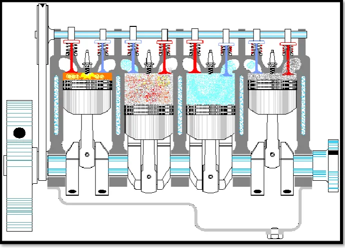
Figure 2.1: Four stroke operational of internal combustion engine ... 6
Figure 2.2: Intake filtration system ... 7
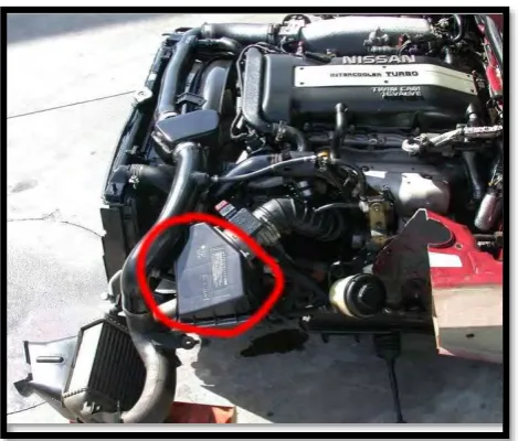
Figure 2.3: Air intake system located ... 8
Figure 2.4: Air box and air filter unit ... 8
Figure 2.5: Modern air system diagram ... 10
Figure 2.6: Drop in air filter ... 12
Figure 2.7: Open pod air filter ... 12
Figure 2.8: Paper filter ... 13
Figure 2.9: Foam type ... 14
Figure 2.10: Cotton type ... 14
Figure 2.11: Stainless steel type... 15
Figure 2.12: Pressure Transducer setup (Abbas Mohammed Ismael1, 2015) ... 16
Figure 2.13: Fuel economy for newer vehicles (all fuel injected with closed-loop control and one equipped with MDS. Range bars show the minimum and maximum for each data set. (Kevin Norman, February 2009) ... 19
Figure 2.14: Fuel economy for carburetted engine. Range bars show the minimum and maximum for each data set. (Kevin Norman, February 2009) ... 19
CHAPTER 3 Figure 3.1: Clogged air filter ... 24
Figure 3.2: New OEM air filter ... 25
Figure 3.3: Performance air filter ... 26
Figure 3.4: Perodua Viva 1.0 engine ... 27
Figure 3.5: Chassis dynamometer ... 28
Figure 3.6: Dynamometer sofware ... 29
Figure 3.7: Shows the control buttons on the front of the gas analyzer ... 30
Figure 3.8: Rear panel ... 31
xv CHAPTER 4
Figure 4.1: Chassis dynamometer ... 33
Figure 4.2: Exhaust gas analyser ... 34
Figure 4.3: The result of horsepower for clogged air filter ... 35
Figure 4.4: The result of torque (Nm) for clogged air filter... 36
Figure 4.5: The result of horsepower for new air filter ... 37
Figure 4.6: The result of torque for new air filter ... 38
Figure 4.7: The result of horsepower for performance air filter ... 39
Figure 4.8:The result of torque for performance air filter ... 40
Figure 4.9: Horsepower (HP) vs types of air filter... 44
Figure 4.10: Torque (Nm) vs engine speed (RPM)... 46
Figure 4.11: Graph of carbon monoxide (CO) vs condition of air filter ... 47
Figure 4.12: Graph of oxygen (O2) vs condition of air filter... 48
Figure 4.13: Graph of carbon dioxide (CO2) vs condition of air filter ... 49
Figure 4.14: Graph of hydrocarbon (HC) vs type of air filter ... 50
Figure 4.15: Graph of nitrogen oxide (NOx) vs types of air filter ... 51
Figure 4.16: Graph of air fuel ratio vs types of air filter ... 52
CHAPTER 5 Figure 5.1: Graph of effect air filter on horsepower (hp) ... 54
Figure 5.2: Graph of torque vs types of air filter ... 55
xvi
LIST OF TABLES
CHAPTER 2
Table 2.1: List of common exhaust gas ... 17
CHAPTER 3 Table 3.1: Engine specification ... 27
CHAPTER 4 Table 4. 1: Dyno result for clogged air filter ... 35
Table 4.2: Dyno result for new OEM air filter... 37
Table 4.3: Dyno result for performance air filter ... 39
Table 4.4: exhaust emission data for clogged air filter ... 41
Table 4.5: exhaust emission data for new air filter ... 42
xvii
LIST OF ABBREVIATIONS
OEM - Original Equipment Manufacturing
RPM - Revolution Per Minute
HP - Horsepower
HC - Hydrocarbon
CO - Carbon Monoxide
CO2 - Carbon Dioxide
O2 - Oxygen
NOx - Nitrogen Oxide
1
CHAPTER 1
INTRODUCTION
1.0 Introduction
The primary function of the intake system is to keep the outside air to achieve your engine for breathing. A decent air intake system takes into consideration perfect and nonstop air into the engine, in this manner accomplishing more power and better mileage for your car’s engine. A modern vehicle air intake system has three primary parts that is air filter, mass flow sensor and throttle body. It is located specifically behind the front grille, the air intake system keeps support air through a long plastic tube going into the air filter housing, which will be blended with the car fuel. At that point the air will be sent to the intake manifold that provisions the fuel and air mixture to the combustion chamber of the engine.
An air filter is a critical part of a vehicle intake system, since it is through the air the air intake part as filtration of the engine to breath. A vehicle’ engine requires a correct mixture of fuel and air keeping in mind the end goal to work, and the greater part of the air enters the system first through the air filter. The air filter is a device that filter any foreign particles and other particles all around to keeping them from entering the intake system that can harming the vehicle’s engine. The air filter is normally fitted in a plastic tube in an air duct to the throttle valve assembly. In vehicles, air is required in the combustion chamber where fuel is burned to produce power. There are only two types of air filters available in the market, an open pod air filter or a drop in air filter.
2 plug and play for consumers, as we can simply change original air filter to the aftermarket air filter for these things. Choosing on which to get for your vehicle is simple. It all depends on the type of transmission your vehicle uses. An automatic transmission’s car will get benefit from a drop in filter, but will have little or no improvements if fitted with an open pod filter.
Using an open pod filter require a minimum rev at 3,000 rpm and above to be able to perform optimally and automatic cars generally change gears before the 3,000 rpm. Manual transmission cars however get benefit from both open pod and drop in filters, as the engine accelerate easier and the driver can decide when to change gears.
1.1 Project Title
Study of engine performance effect using variable air filter on Perodua Viva 1.0 Engine
1.2 Problem Statement
3 A clean air filter will offer the efficient and better air flow through the engine cylinder. As the air filter become clogged, the function of air filter to do the filtration is decrease. Due to this condition, the quantity of air that is supply to the engine is a little bit and cause the performance of the engine drop. While the performance air filter can support high and better air flow than standard air filter which can increase the air intake pressure to the engine. As we know when the high compressed air entering the engine can increase the performance and torque as well because of leaner air fuel mixture occur in the engine.
At the same time, it can give engine better fuel economy. Besides that, with better filtration it can minimize the car’s emission. This is because of the type of material that used to develop this air filter. For this study I choose to use only drop in air filter for the engine in three conditions that is clogged air filter, new air filter and performance air filter.
As a consumer we need to choose the right air filter that we going to use to the vehicle. Usually the maintenance of air filter is underestimated by the consumer and lastly cause the engine performance drop. In certain cases, the consumers forgot to change their air filter because the air filter changing takes every 40,000km based on Perodua owner’s manual book.
1.3 Objective
Study effect using three condition type of air filter (clogged, new OEM and performance) and its effect to the performance of the engine’s horsepower, torque and exhaust emission.
To compare the result between using clogged, new or performance air filter.
4 1.4 Project Scope
5
CHAPTER 2
LITERATURE REVIEW
2.0 Internal Combustion Engine
The internal combustion engine is an engine in which the burning of a fuel occurs in an enclosed space called as a combustion chamber. This exothermic reaction of a fuel with an oxidizer creates gases of high temperature and pressure, which are permitted to expand. The feature that indicate of an internal combustion engine is that work is performed by the expanding hot gases acting directly to cause movement. For example, by acting on pistons, rotors, or even by pressing on and indirectly will stir the entire part of the engine. The piston's movement then, turns a crankshaft that then turns the car wheels via transmission system of vehicle. The types of fuel commonly used for internal combustion engines are petrol, diesel, and kerosene.
Many people claimed the invention of the internal combustion engine in the 1860's, but only one has the patent on the four stroke operating sequence. In 1867, Nikolaus August Otto, a German engineer, developed the four-stroke "Otto" cycle, which is widely used in transportation even today. Otto developed the four-stroke internal combustion engine when he was 34 years old.
6 The term Internal Combustion Engine (ICE) is almost always used to refer specifically to reciprocating engines, Wankel engines and similar designs in which combustion is intermittent. However, continuous combustion engines, such as Jet engines, most rockets and many gas turbines are also internal combustion engines.
[image:22.595.163.509.281.530.2]Internal combustion engines are seen mostly in transportation. Several other uses are for any portable situation where you need a non-electric motor. The largest application in this situation would be an Internal combustion engine driving an electric generator. That way, you can use standard electric tools driven by an internal combustion engine.
Figure 2.1: Four stroke operational of internal combustion engine
2.1 Intake System
7 sensor, a throttle body and an intake manifold, despite everything they act as a similar fundamental capacity that basic air bays did in early vehicles.
Component of Intake System
Modern (fuel injected) systems consist of little more than an air inlet, but this system typically includes:
Air filter
Mass flow sensor Intake manifold Throttle body
8 Figure 2.3: Air intake system located