City, University of London Institutional Repository
Citation
:
Rane, S. (2015). Grid Generation and CFD Analysis of Variable Geometry Screw Machines. (Unpublished Doctoral thesis, City University London)This is the accepted version of the paper.
This version of the publication may differ from the final published
version.
Permanent repository link: http://openaccess.city.ac.uk/15129/
Link to published version
:
Copyright and reuse:
City Research Online aims to make research
outputs of City, University of London available to a wider audience.
Copyright and Moral Rights remain with the author(s) and/or copyright
holders. URLs from City Research Online may be freely distributed and
linked to.
Grid Generation and CFD Analysis of Variable
Geometry Screw Machines
By
Sham Ramchandra Rane
Thesis submitted for the degree of Doctor of Philosophy
in Mechanical Engineering
City University London
School of Mathematics, Computer Science and Engineering
1 | P a g e
“Having considerable confidence in the method I was using in deducing the equations of
motion from the fundamental assumption; it naturally occurred to me to re-examine the
fundamental assumptions, to see if these had been introduced into the theory in their fullness.
It was then I observed that the theory, both as applied by Maxwell, and myself, neglected any
possible dimensions of a molecule, and it became clear that by neglecting this we had neglected
that which made it possible for the boundary to produce an acceleration on the fluid.”
– Professor Osborne Reynolds
On the equations of motion and the boundary conditions for viscous fluids
i | P a g e
Table of Contents
List of Figures ... v
List of Tables ... x
Acknowledgement ... xi
Declaration ... xii
Abstract ... xiv
Nomenclature ... xv
Chapter 1 – Introduction ... 1
1.1 Introduction ... 1
1.2 Twin Screw Compressor ... 2
1.3 Single Screw Compressor ... 4
1.4 Variable Geometry Screw Machines... 6
1.4.1 Variable pitch twin screw compressor ... 7
1.4.2 Variable profile parallel axis twin screw compressor ... 10
1.4.3 Tri-rotor screw compressors ... 11
1.4.4 Single screw compressor variants ... 11
1.4.5 Spiral compressor and expander ... 12
1.4.6 Internal Conical Rotary Screw Compressor ... 13
1.5 Computational methods for fluid flow calculations ... 13
1.6 Grid generation approaches in practise ... 15
1.7 Motivation to investigate grid generation in numerical methods ... 17
Chapter 2 – Literature Review ... 19
2.1 Numerical analysis of Screw machines using lumped parameter models ... 20
2.2 CFD analysis of Screw Compressors and Expanders ... 23
2.3 Summary ... 26
Chapter 3 – Research Aims and Contribution to Knowledge... 27
3.1 Aims of research... 27
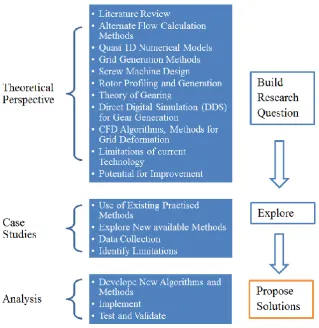
3.2 Methodology ... 27
3.3 Contribution to knowledge ... 28
ii | P a g e
4.1 Introduction ... 30
4.2 Governing equations for deforming domains... 30
4.3 Solution of governing equations ... 34
4.3.1 Diffusion equation based mesh smoothing ... 35
4.3.2 User defined nodal displacement ... 35
4.3.3 Key-Frame grid re-meshing ... 36
4.4 Investigation of Key-frame grid remeshing technique ... 37
4.5 Algebraic approach for grid generation of twin screw machines ... 43
4.6 Differential approach for grid generation of twin screw machines ... 45
4.7 Comparison of the two approaches ... 47
4.8 Summary ... 49
Chapter 5 – Grid Generation for Variable Geometry Screw Machines ... 50
5.1 Introduction ... 50
5.2 Development of the algebraic approach to improve cross section grid ... 52
5.2.1 Distribution from outer boundary to inner boundary ... 53
5.2.2 Coordinate transformation of the full rotor region ... 55
5.2.3 Regularisation by skewed sine function... 58
5.2.4 Example of grids with conformal interface ... 63
5.2.5 Regularisation by background block distribution ... 65
5.2.6 Example of grids with interlobe refinement ... 72
5.2.7 Example of grid with one to one connected interface ... 73
5.2.8 Comparison of grid quality parameters ... 74
5.3 Grid generation for variable pitch and variable profile screw rotors ... 79
5.3.1 Integration of 2D grid sections into a 3D mesh ... 79
5.3.2 Grid generation for variable lead rotors ... 84
5.3.3 Grid generation for variable profile rotors ... 87
5.3.4 Examples of grids with variable pitch and uniform profile ... 90
5.3.5 Examples of grid with uniform pitch and variable profile ... 91
5.3.6 Example of grid for internal conical rotary compressor ... 93
5.4 Development of inflation layer grid ... 94
5.4.1 Calculation of the node spacing ... 95
5.5 Summary ... 97
iii | P a g e
6.1 Introduction ... 98
6.2 Analysis of a 3/5 synchronised Dry Air Compressor ... 100
6.2.1 Case description ... 100
6.2.2 Pressure based coupled solver ... 101
6.2.3 Pressure based segregated solver ... 103
6.2.4 Experimental measurement ... 104
6.2.5 Results and discussion ... 107
6.2.6 Inference from comparison of solvers ... 112
6.2.7 Influence of interlobe grid refinement on performance prediction ... 113
6.2.8 Influence of inflation layer on the performance prediction ... 118
6.3 Analysis of a 3/5 synchronised Dry Air Expander ... 124
6.3.1 Case description ... 125
6.3.2 Simulation ... 126
6.3.3 Results and Discussion ... 128
6.3.4 Evaluation of overall performance characteristics ... 134
6.3.5 Influence of inflation layer grid on performance ... 136
6.3.6 Inference ... 140
6.4 Analysis of Variable Geometry Dry Air Screw Compressor ... 142
6.4.1 Case description ... 143
6.4.2 Simulation ... 147
6.4.3 Results and Discussion ... 147
6.4.4 Inference ... 156
6.5 Closure ... 157
Chapter 7 – Conclusions and Recommendation for Future Work... 158
7.1 Summary of the research ... 158
7.2 Conclusions ... 159
7.3 Recommendations for future work ... 161
References ... 163
Appendices ... 177
Screw compressor performance parameters ... 178
iv | P a g e
B.1 Algebraic grid generation ... 181
B.2 Coordinate transformation... 181
B.3 Lagrange basis polynomial interpolation ... 183
B.4 Hermite interpolation polynomial ... 184
B.5 Differential grid generation ... 187
B.6 Variational grid generation... 192
Characteristic domain decomposition ... 194
C.1 Analytical rack ... 196
C.2 Numerical rack ... 197
C.3 Differential division line ... 199
Algebraic approach for Grid Generation of Twin Screw Rotors ... 201
D.1 Coordinate transformation of interlobe rotor space ... 201
D.2 Rotor boundary adaptation ... 202
D.3 Outer boundary regularisation ... 205
D.4 Interior nodes distribution ... 209
D.5 Grid orthogonalisation... 212
D.6 Grid smoothing ... 213
Differential approach for Grid Generation of Twin Screw Rotors ... 215
v | P a g e
List of Figures
Figure 1.1 Classification of common industrial compressors ... 2
Figure 1.2 Oil injected twin screw compressor and its working chamber ... 2
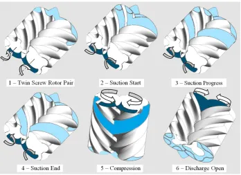
Figure 1.3 Operating stages in a twin screw compressor... 3
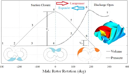
Figure 1.4 Typical pressure and volume variation in a twin screw compressor ... 4
Figure 1.5 Geometry and basic components of a single-screw compressor ... 5
Figure 1.6 Single screw compressor rotors ... 5
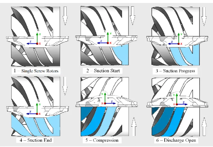
Figure 1.7 Operating stages in a single screw compressor ... 6
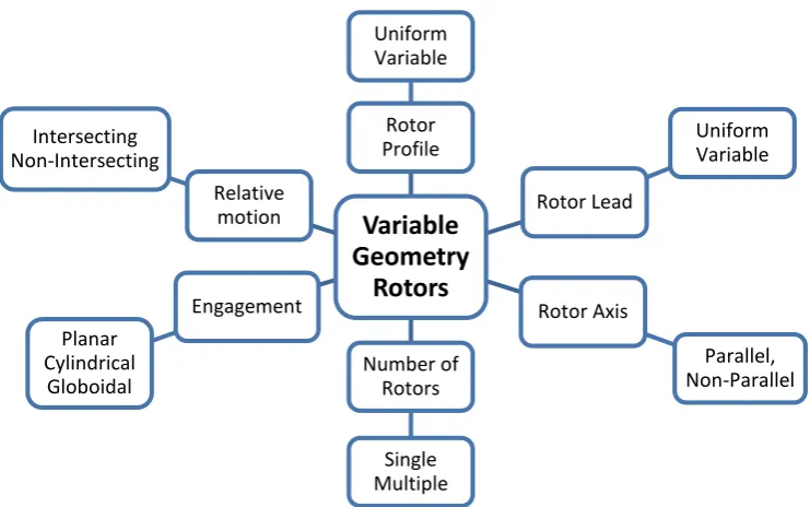
Figure 1.8 Concept of variable geometry screw machines ... 7
Figure 1.9 Meshing of uniform pitch twin screw rotors ... 8
Figure 1.10 Meshing of variable pitch twin screw rotors ... 8
Figure 1.11 Comparison of displacement curve ... 8
Figure 1.12 Comparison of compression curve ... 8
Figure 1.13 Cylinder and port development of a rotor pair ... 9
Figure 1.14 Meshing of variable profile parallel axis twin screw rotors ... 10
Figure 1.15 Tri rotor screw compressor ... 11
Figure 1.16 Single screw compressor configuration variants ... 12
Figure 1.17 Spiral compressor and expander configuration ... 12
Figure 1.18 Internal twin screw compressor configuration ... 13
Figure 1.19 Basic grid generation techniques ... 16
Figure 1.20 Non-conformal interface between the two rotors ... 18
Figure 1.21 Merged nodes at the CUSP point to capture blow-hole ... 18
Figure 2.1 Conical rotors with SRM 4/6 profile. ... 23
Figure 3.1 Research methodology ... 28
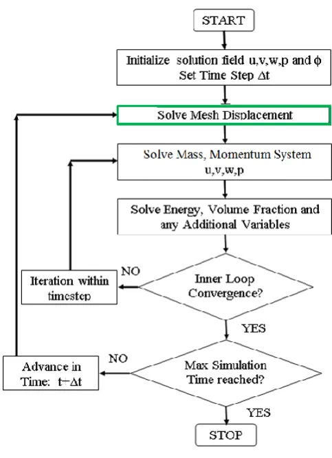
Figure 4.1 Flow chart of solution process with deforming domains ... 34
Figure 4.2 Grid deformation using Diffusion equation mesh smoothing ... 35
Figure 4.3 Grid deformation using User defined nodal displacement ... 36
Figure 4.4 Grid deformation using Key-Frame grid re-meshing ... 36
Figure 4.5 Hexahedral mesh using Diffusion smoothing (SH1)... 38
Figure 4.6 Tetrahedral mesh used in Key-frame re-meshing (KR1) ... 39
Figure 4.7 Piston displacement plot ... 39
Figure 4.8 Cyclic pressure history ... 40
vi | P a g e
Figure 4.10 Error in pressure predictions of adiabatic cycles ... 41
Figure 4.11 Error in temperature predictions of adiabatic cycles ... 42
Figure 4.12 Simplified block diagram – Algebraic rotor grid generation ... 44
Figure 4.13 Simplified block diagram – Differential rotor grid generation ... 46
Figure 5.1 Grid generation developments for twin screw rotors ... 51
Figure 5.2 Non-conformal interface between the two rotors ... 52
Figure 5.3 Merged nodes at the CUSP point to capture blow-hole ... 53
Figure 5.4 Distribution of nodes on the outer boundary ... 55
Figure 5.5 Point distribution on inner boundary and outer circle ... 56
Figure 5.6 Forward transformation of full rotor region to computational domain ... 57
Figure 5.7 Reverse transformation of full rotor region to physical domain ... 58
Figure 5.8 Use of skewed sine function to regularise distribution ... 60
Figure 5.9 Effect of skewness of skewed sine function on distribution ... 60
Figure 5.10 Effect of amplitude of skewed sine function on distribution ... 61
Figure 5.11 Regularised distribution obtained with skewed sine function ... 62
Figure 5.12 Reverse transformation of the regularised distribution ... 62
Figure 5.13 Conformal grids generated with sine function in a Roots blower rotor ... 63
Figure 5.14 Conformal grid generated with sine function in a Screw Compressor rotor ... 64
Figure 5.15 Notch defects on the rotor surface in 3D grids ... 65
Figure 5.16 Background blocking for the main and gate rotors ... 67
Figure 5.17 Using blocks to get rotor profile distribution ... 68
Figure 5.18 Refinement in the rack segment and superimposition of rack curve ... 69
Figure 5.19 Grid generated with background blocking in screw compressor rotor... 70
Figure 5.20 Surface mesh on the rotor, casing and the rack interface ... 71
Figure 5.21 Examples of grids with interlobe refinement ... 73
Figure 5.22 Example of grids with one to one connected interface... 74
Figure 5.23 Comparison of Grid A and Grid B - % cells vs Quality factor ... 75
Figure 5.24 Comparison of cells with Equi-angle Skew factor < 0.15 ... 76
Figure 5.25 Comparison of regions with aspect ratio > 200 ... 77
Figure 5.26 Comparison of cells with Determinant < 0.1... 77
Figure 5.27 Comparison of cells with MaxWarp factor > 50 ... 78
Figure 5.28 Grid generation for rotors with uniform lead ... 80
vii | P a g e
Figure 5.30 Axial spacing difference between uniform pitch and variable pitch grids ... 82
Figure 5.31 SCORG structure for variable pitch and variable profile rotors... 83
Figure 5.32 Section angular rotation with axial distance for different Pitch Functions ... 84
Figure 5.33 Variable pitch and variable profile grid generation ... 88
Figure 5.34 Grid assembly in 3D for variable pitch and variable profile rotors ... 89
Figure 5.35 Examples of variable pitch grid with uniform profile on 5/6 ‘N’ rotors ... 90
Figure 5.36 Example of variable geometry rotor grid with uniform pitch ... 91
Figure 5.37 Grid sections of variable geometry rotor, 3/5 ‘Rotor generated N’ profile ... 92
Figure 5.38 Grid of the working chamber for conical internal screw rotors ... 93
Figure 5.39 Construction of inflation layer adjacent to rotor surface ... 94
Figure 5.40 Inflation layer subroutine with the main grid generation ... 95
Figure 5.41 Example inflation layer with 8 divisions and growth rate 1.2 ... 96
Figure 6.1 Screw compressor – a) The machine and b) Extracted flow model ... 101
Figure 6.2 Overview of the pressure based solver ... 101
Figure 6.3 Tetrahedral mesh in Solver-1 ... 103
Figure 6.4 Body-fitted binary tree mesh in Solver-2 ... 103
Figure 6.5 Experimental setup for performance measurement ... 105
Figure 6.6 Location of interlobe pressure transducers on the compressor ... 105
Figure 6.7 Pressure-Angle diagram a) 6000 rpm, b) 8000 rpm ... 107
Figure 6.8 Comparison of mass flow rate and indicated power ... 108
Figure 6.9 Comparison of full range mass flow rate and indicated power ... 108
Figure 6.10 Comparison of specific power and volumetric efficiency ... 109
Figure 6.11 Comparison of full range specific power and volumetric efficiency ... 110
Figure 6.12 Comparison of velocity and density in leakage gaps ... 111
Figure 6.13 CFD Model Domain and Grid refinements in the interlobe clearance ... 114
Figure 6.14 Pressure contours on the rotor surface with Base grid and Grid – 4 ... 115
Figure 6.15 Pressure variation in the chamber with at 6000 and 8000rpm ... 115
Figure 6.16 Comparison of Indicated power and Flow rate ... 116
Figure 6.17 Comparison of Volumetric efficiency and Indicated Specific power ... 117
Figure 6.18 Example of Inflation layer grid on the two rotors ... 119
Figure 6.19 Comparison of velocity profile close to discharge port ... 120
Figure 6.20 Comparison of gas velocity adjacent to Male Rotor ... 120
viii | P a g e
Figure 6.22 Comparison of Wall Shear proximate to the Male Rotor ... 122
Figure 6.23 Pressure Angle diagram with Inflation layer grid ... 123
Figure 6.24 Numerical grid of the GL-51.2 screw expander rotors ... 124
Figure 6.25 Flow domains for analysis of the twin screw expander ... 125
Figure 6.26 Variation of pressure in a twin screw expander ... 128
Figure 6.27 Influence of clearance variation on P-Angle at 4000rpm ... 130
Figure 6.28 Influence of clearance variation on P-Angle at 10000rpm ... 130
Figure 6.29 Influence of the location of high pressure boundary on P-Angle ... 131
Figure 6.30 Influence of high pressure boundary condition on P-Angle ... 132
Figure 6.31 Influence of laminar and turbulence model on P-Angle ... 133
Figure 6.32 Mass flow rate Vs CFD case variants... 134
Figure 6.33 Indicated power Vs CFD case variants ... 134
Figure 6.34 Power vs. Speed at different filling pressures ... 135
Figure 6.35 Mass flow rate vs. Speed at different filling pressures ... 135
Figure 6.36 Cross section grid of the expander with inflation layer on the rotors ... 136
Figure 6.37 Comparison of velocity profile close to high pressure port ... 137
Figure 6.38 Comparison of gas velocity adjacent to Male Rotor ... 138
Figure 6.39 Comparison of Pressure Angle diagram with Inflation layer grid ... 139
Figure 6.40 Comparison of power and mass flow rate with inflation layer grid ... 140
Figure 6.41 Twin screw compressor and its working chamber ... 142
Figure 6.42 CFD model – flow domain of the twin screw compressor ... 143
Figure 6.43 Meshing of Uniform Pitch Twin Screw Rotors ... 143
Figure 6.44 Meshing of Variable Pitch Twin Screw Rotors ... 143
Figure 6.45 Reduced discharge port area in Case 2 compared with Case 1 ... 144
Figure 6.46 Variable pitch grid – 3/5 ‘N’ rotors ... 144
Figure 6.47 Variable profile grid – 3/5 ‘N’ rotors ... 145
Figure 6.48 Three levels of grid refinements shown for one section... 146
Figure 6.49 Pressure variation on variable pitch rotor with discharge at 2.0bar. ... 148
Figure 6.50 Indicator diagram for cases calculated on fine grid with discharge at 2.0 bar. .. 148
Figure 6.51 Indicator diagram for cases calculated on fine grid with turbulence models. .... 149
Figure 6.52 Effect of grid refinement on integral parameters ... 150
Figure 6.53 Effect of grid refinement on pressure diagram ... 150
ix | P a g e
Figure 6.55 Comparison of interlobe sealing line lengths ... 152
Figure 6.56 Comparison of Blow-hole area ... 153
Figure 6.57 Comparison of performance parameters ... 155
Figure B.1 Mapping of a curved physical region onto a rectangle ... 182
Figure B.2 Mapping of a unit square onto a curved four sided region ... 185
Figure B.3 Mapping of a unit square by projector 𝑷 ... 186
Figure B.4 TFI mapping of a unit square by composite projector 𝑷 𝑷 ... 187
Figure B.5 Differential construction of a 2D curvilinear grid ... 188
Figure B.6 Specification of first mesh interval and angle in Sorenson’s method ... 191
Figure C.1 Characteristic decomposition of a screw compressor ... 195
Figure C.2 Main rotor, Gate rotor and Rack curves in meshing condition ... 197
Figure C.3 Analytical rack as a splitting curve for O blocks ... 197
Figure C.4 Rack cut from rotor profile using DDS ... 199
Figure C.5 Differential equipotential as a splitting curve for O blocks ... 200
Figure D.1 Coordinate transformation from rotor region to computational region ... 201
Figure D.2 Coordinate transformation from interlobe region to computational region ... 202
Figure D.3 Sinus adaptation function on the gate rotor profile ... 205
Figure D.4 Point distribution on inner boundary and outer circle ... 206
Figure D.5 Transformation of interlobe region to computational domain ... 207
Figure D.6 Regularised distribution on the outer boundary ... 209
Figure D.7 Explicit orthogonalisation of grid lines ... 212
Figure D.8 Orthogonalisation of the gate rotor mesh ... 213
Figure D.9 Influence of iterative smoothing on grid lines ... 214
Figure E.1 Solution to Laplace equation with fixed boundary conditions ... 215
Figure E.2 Transition of division line ... 217
Figure E.3 Basic grid generated by the differential approach ... 218
x | P a g e
List of Tables
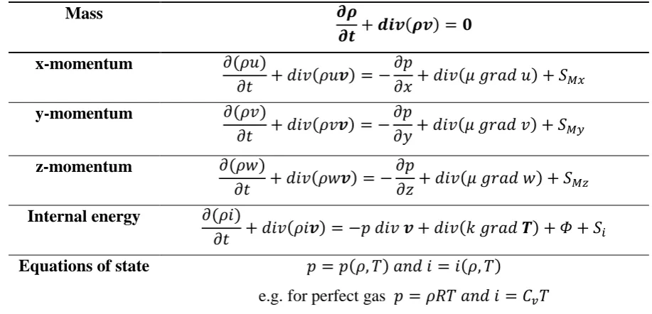
Table 4.1 Conservative form of the governing equations of the flow of a compressible
Newtonian fluid ... 31
Table 4.2 Error in Pressure, Temperature and Gas Mass ... 41
Table 4.3 Comparison of algebraic and differential approach for screw rotor grids ... 47
Table 6.1 Solver-1 modelling parameters (used by ANSYS CFX) ... 102
Table 6.2 Solver-2 modelling parameters (used by PumpLinx) ... 104
Table 6.3 Test rig instrumentation details... 106
Table 6.4 Grid levels and number of divisions. ... 113
Table 6.5 Grid size comparison with inflation layers ... 118
Table 6.6 Rotor tangential velocity at root diameter ... 119
Table 6.7 Comparison of results with inflation layer grid ... 123
Table 6.8 Cases evaluated for the analysis in Stage I ... 127
Table 6.9 Experimental test results for Expander GL 51.2 ... 128
Table 6.10 CFD model performance prediction of GL 51.2 ... 134
Table 6.11 Rotor grid size comparison with inflation ... 136
Table 6.12 Rotor tangential velocity at root diameter ... 138
Table 6.13 Comparison of results with inflation layer grid ... 139
Table 6.14 Grid refinement as number of computational nodes ... 147
Table 6.15 Comparison of Interlobe Sealing Line Length ... 152
Table 6.16 Comparison of Blow-hole area ... 154
Table 6.17 Comparison of variable geometry rotor efficiencies ... 154
xi | P a g e
Acknowledgement
Presented thesis is a result of research carried out at the Centre for Positive Displacement
Compressor Technology of City University London between 2011 and 2015. I am very
thankful to the University for granting me financial assistance and allowing me to use the
computational resources for this investigation.
Professor Ahmed Kovačević has been an inspiration and his work on the subject of grid
generation and CFD in screw machines forms the basis of the presented study. I am grateful to
him that he encouraged and supported my research with perseverance and generosity.
Professor Nikola Stošić has been a remarkable teacher. His explanations of the physical
processes inside screw machines helped in interpretation of results and I am very thankful to
him for his enthusiasm and support.
Professor Ian Smith has helped me from time to time to shape the thesis in its meaningful form
with corrections in English and scientific terminologies. I am grateful for his support and
kindness.
Design and experimental data for expander performance was provided by TU Dortmund and I
am thankful to Professor Andreas Brümmer for his help.
I am highly indebted to my wife, my mother and my father who supported me and gave me all
the help that could have been possible during this period. My elder brother and my twin sister
encouraged my ideas cheerfully. My father through his manufacturing firm Maya Engineering
Works; generously funded my studies. Without my family’s love I would not have the same
courage.
I also thank all my colleagues and friends for their help and advices. Dr Ashvin Dhunput, Ms
Madhulika Kethidi, Ms Ekaterina Chukanova, Dr Matthew Read, Mr Mohammed Arjeneh and
laboratory technicians Mr Mike Smith, Mr Jim Ford are a few of them to mention.
Sham Ramchandra Rane
xii | P a g e
Declaration
COVERED WORK
I, Sham Ramchandra Rane, 2 Loring Road, London TW76QA , “the Depositor”,
would like to deposit “Grid Generation and CFD Analysis of Variable Geometry Screw
Machines”,
here after referred to as the “Work”,
in the City University Institutional Repository and agree to the following:
NON-EXCLUSIVE RIGHTS
Rights granted to the City University Institutional Repository through this agreement are
entirely non-exclusive and royalty free. I am free to publish the Work in its present version or
future versions elsewhere. I agree that the City University Institutional Repository
administrators or any third party with whom the City University Institutional Repository has
an agreement to do so may, without changing content, translate the Work to any medium or
format for the purpose of future preservation and accessibility.
DEPOSIT IN THE CITY UNIVERSITY INSTITUTIONAL REPOSITORY
I understand that work deposited in the City University Institutional Repository will be
accessible to a wide variety of people and institutions - including automated agents - via the
World Wide Web. I also agree to an electronic copy of my thesis being included in the British
Library Electronic Theses On-line System (EThOS).
I understand that once the Work is deposited, a citation to the Work will always remain visible.
Removal of the Work can be made after discussion with the City University Institutional
Repository, who shall make best efforts to ensure removal of the Work from any third party
xiii | P a g e
I AGREE AS FOLLOWS:
- That I am the author or co-author of the work and have the authority on behalf of the author
or authors to make this agreement and to hereby give the City University Institutional
Repository administrators the right to make available the Work in the way described above.
- That I have exercised reasonable care to ensure that the Work is original, and does not to the
best of my knowledge break any UK law or infringe any third party’s copyright or other
Intellectual Property Right. Where I have included third party copyright material, I have fully
acknowledged its source.
- The administrators of the City University Institutional Repository do not hold any obligation
to take legal action on behalf of the Depositor, or other rights holders, in the event of breach of
intellectual property rights, or any other right, in the material deposited.
Sham Ramchandra Rane
xiv | P a g e
Abstract
This thesis describes the development of grid generation and numerical methods for predicting
the flow in variable geometry, positive displacement screw machines.
It has been shown, from a review of available literature, that the two main approaches available
to generate deforming grids for the CFD analysis of 3D transient flow in screw machines are
algebraic and differential. Grids that maintain the cell count and connectivity, during solution,
provide the highest accuracy and customised grid generation tools have the capability to
accommodate large mesh deformations. For the analysis of screw rotors with a variable lead or
varying profile, these techniques are suitable but are required to be developed further with new
procedures that can define the three dimensional variation of geometry of the rotors onto the
computational grid.
An algebraic grid generation method was used for deforming grid generation of variable lead
and varying profile rotors. Functions were developed for correlating a specified lead variation
along the rotor axis with the grid spacing. These can be used to build a continuously variable
lead with linear, quadratic or higher order functions. For variable profile rotors, a novel
approach has been developed for three dimensional grid structuring. This can be used to specify
a continuously variable rotor profile, a variable lead, and both internal and external rotor
engagement, thus making it possible to generate rotor domains with conical and variable lead
geometries. New grid distribution techniques were developed to distribute boundary points on
the rotors from the fixed points on the rack and the casing. These can refine the grid in the
region of interlobe leakage gaps between the rotors, produce a one to one connected interface
between them and improve the cell quality. Inflation layers were applied and tested for mesh
refinement near the rotor boundaries. Case studies have been presented to validate the proposed
grid generation techniques and the results have been compared with experimental data.
Simulated results agreed well with measured data and highlighted the conditions where
deviations are highest. Results with variable geometry rotors showed that they achieve steeper
internal pressure rise and a larger discharge port area could be used. With variable lead rotors
the volumetric efficiency could be improved by reducing the sealing line length in the high
pressure zone. Calculations with inflation layers showed that local velocities were better
xv | P a g e
Nomenclature
𝑎, 𝑏, 𝑐 - transformation parameters 𝑞∅𝑠 - flux source in general transport
equation
𝒂𝑙, 𝒃𝑙 - boundary points 𝑞∅𝑉 - volume source in general
transport equation 𝐴𝑠𝑘 - amplitude of sine function 𝒓 - radius vector
𝑏𝑖 - constant 𝒓𝒃(𝑥, 𝑦) - Blocking node position vector
𝐁𝑖 - Blocking index 𝑟, 𝜃 - polar coordinates of a point
𝑐𝑖 - concentration of species 𝑟𝑝𝑚 - rotor speed 𝑐1˗𝑐4 - tension spline coefficients 𝑅𝑒 - Reynolds number 𝐶1, 𝐶2 - coefficients of orthogonalisation
procedure
𝑆 - cell surface
𝐶𝑝 - specific heat at constant
pressure
𝑠 - transformed coordinate
𝐶, 𝜎 - constants in 𝑘 𝜀 turbulence
model
𝑆𝑐𝑖 - source term of species
𝐷 - outer diameter 𝐒 - viscous part of stress tensor
𝑑𝑖𝑣 - divergence operator 𝑡 - time
𝑓𝑖(𝑠) - adaptation variable 𝑇 - temperature
𝐹𝑖(𝑠) - integrated adaptation variable 𝐓 - stress tensor
𝑓(𝑡) - skewed sine function 𝑇𝑔𝑎𝑡𝑒 - gate rotor torque 𝑓(,) - stretching functions 𝑇𝑚𝑎𝑖𝑛 - main rotor torque
𝑔𝑟𝑎𝑑 - gradient operator 𝐮 - displacement vector
𝑔𝑟 - Growth rate of inflation 𝑛𝑙𝑎𝑦𝑒𝑟𝑠 - Number of layers in inflation ℎ1˗ℎ4 - blending functions of Hermite
interpolation
𝑢𝑖 - Cartesian component of velocity
vector
ℎ - enthalpy 𝐯 - fluid velocity
𝑖 - internal energy 𝐯𝒃 - surface velocity
𝑗𝑎 - number of angular divisions of 𝜑
𝑉 - cell Volume
𝑘 - turbulent kinetic energy 𝑉𝑖 - built in volume index
xvi | P a g e
𝐾 - number of points 𝑉𝑑 - discharge open volume
𝐿 - rotor length 𝑉̇ - volumetric flow rate
𝑚 - mass 𝑤 - weight factor
𝑚̇ - mass flow rate 𝑊 - weight function
𝑛 - rotor speed 𝑊𝑖𝑛𝑑 - indicated work
𝑛𝑠𝑘 - frequency of sine function 𝑥, 𝑦, 𝑡 - rotor profile parameters 𝒏 - cell face normal vector 𝑋 - grid spacing
𝑝 - pressure 𝑥, 𝑦, 𝑧 - Cartesian coordinates
𝑝𝑖 - local lead 𝑋, 𝑌, 𝑍 - points on physical boundaries
𝑝𝑠 - starting lead 𝑥𝑝, 𝑦𝑝 - coordinates of calculation point
P
𝑝𝑒 - ending lead 𝑦𝑝′, 𝑦𝑝" - first and second derivatives in
vicinity of the point P
𝑝𝑠𝑡 - starting pitch 𝑧1 - Number of lobes on main rotor
𝑝𝑒𝑛 - ending pitch 𝑧2 - Number of lobes on gate rotor
𝑝(𝑥) - polynomial ∆𝑡 - time step
𝑃𝑖𝑛𝑑 - indicated power ∆𝑧 - increment in rotor axial
direction
𝑷 , 𝑷 - projector functions 𝑷 𝑷 - composite mapping
Greek symbols
𝛼, 𝛽 - tension spline coefficients 𝜌 - density
𝛼1, 𝛽1 - blending functions 𝜎 - tension spline parameter 𝛼𝑖 - male rotor rotation angle 𝑤 - wrap angle
∆𝛼 - step of male rotor rotation angle - intrinsic transport property
𝛾 - adiabatic index 𝜑 - interlobe angle of male rotor
𝛿𝑘,𝑙 - Kronecker delta function , - computational coordinate
𝛿 - displacement 𝛺 - control volume
𝜀 - dissipation of turbulent kinetic
energy
𝛤 - diffusion coefficient in general
transport equation
𝜇 - viscosity 𝜎𝑠𝑘 - skewness of sine function
xvii | P a g e
𝑣 - volumetric efficiency 𝑖 - distance of control point 𝑎𝑑 - adiabatic efficiency ̂𝑖,𝑗 - arc lengths
𝑖𝑠𝑜 - isothermal efficiency
Subscripts
1 - main rotor 𝑖𝑠𝑜 - isothermal
2 - gate rotor 𝑚𝑎𝑥 - maximum
0,1 - suction conditions 𝑚𝑖𝑛 - minimum
2 - discharge conditions 𝑠 - grid values
𝑎𝑑 - adiabatic 𝑠𝑖𝑛𝑑 - specific indicated
𝑒𝑓𝑓 - effective 𝑡 - theoretical
𝑖𝑛𝑑 - indicated
Superscripts
𝑛 - time step or iteration level
Abbreviations
ALE – Arbitrary Lagrangian-Eulerian
CFD – Computational Fluid Dynamics
SCORPATH – Screw Compressor Rotor Profiling and Thermodynamics
SCORG – Screw Compressor Rotor Grid Generator
PDE – Partial Differential Equation
TFI – Transfinite Interpolation
GGI – Generalised Grid Interface
1 | P a g e
Chapter 1
– Introduction
1.1
Introduction
Rotary Twin Screw Compressors have been in industrial usage for a long time and were first
proposed in 1878 by Heinrich Krigar in Germany (Stošić et al., 2005a). They are widely used in the oil and gas, process gas extraction, refrigeration and industrial air industries. For a long
period, their development, as compressors or expanders, was limited by their low efficiency
and high manufacturing cost. The asymmetric rotor profile, developed in 1973 (Stošić et al., 2005a), greatly reduced leakage through the blow-hole and, at about the same time, the
introduction of CNC machine tools made it possible to produce helical rotors with complex
profiles. Single screw compressors of the Zimmern type are another type of rotary positive
displacement machine which originated around 1962 (Zimmern, 1984). Today screw machines are regarded as highly reliable and compact systems for energy conversion. Continuing
demands for reduced energy losses and higher gas pressure differences in compact machines
have led to the use of modern analytical tools to predict the flow characteristics and
performance of non-conventional types of screw machine, such as those with rotors of variable
geometry.
The remainder of this chapter contains a basic introduction to various types of screw
compressors, their mode of operation, and some computational methods that can be used for
their performance prediction.
Figure 1.1 shows a classification of commonly used industrial compressors. This is based on
the principle by which the working gas is pressurised and as seen, screw compressors fall in
the category of positive displacement machines. The meaning of positive displacement is that
the gas is compressed by reduction of its volume. This is achieved by simply reducing the
volume of a chamber containing the gas. This chamber is called the working chamber of a
compressor. For a piston-cylinder configuration the working chamber is just a cylinder but for
a screw compressor the working chamber volume is more complex and is formed by two or
more meshing lobed rotors enclosed in a casing. There are two main types of screw compressor
2 | P a g e
Figure 1.1 Classification of common industrial compressors
Screw compressors are further classified as Oil free and Oil injected based on the presence or
absence of oil in the working chamber. The operating principle of both types is the same but in
the oil free compressor the gas is compressed without any contact with the lubricant, whereas
in the oil injected compressor the lubricant is injected into the gas during compression and
removed downstream. Oil free compressors require additional timing gears on the rotor shafts
to maintain contact free operation whereas in oil injected compressors the male rotor usually
drives the female rotor directly.
1.2
Twin Screw Compressor
Figure 1.2 shows an example of an oil injected twin screw compressor. The main elements of
the machine and working chamber have been highlighted.
Figure 1.2 Oil injected twin screw compressor and its working chamber Single Screw Scroll
Compressors
Positive Displacement Aerodynamic
Reciprocating Rotary
Centrifugal Axial Ejector
One Shaft Two Shafts Three Shafts Piston Diaphragm
Sliding Vane Liquid Ring
3 | P a g e
There are six leakage paths identified in this type of machine (Fleming et. al., 1994, 1998,
Hanjalić and Stošić, 1997) the rotor interlobe leakage, rotor leading edge tip leakage, trailing edge tip leakage, the high pressure side and low pressure side axial end leakage and the high
pressure side blow-hole leakage.
Operating Principle
The working principle of these machines with the rotors in the form of helical lobed screws is
simple. The male rotor engages with the female rotor forming a closed interlobe space with the
housing. The working chamber of the compressor between the rotors and the casing is shown
in Figure 1.3-1.
Figure 1.4 shows the volume and pressure variation in the working chamber in one compression
cycle. The numbers on the diagram indicate the state of gas in the process. When the lobes
disengage at one end, suction is created. As the volume between the lobes continuously
increases it draws in the working fluid – Figure 1.4 – 2. Further rotation of the rotor traps this
volume between the rotors and the casing. Because of the helical twist on the lobes, the rotation
[image:23.595.124.473.392.645.2]of the rotor causes an axial displacement of fluid – Figure 1.4 – 4.
Figure 1.3 Operating stages in a twin screw compressor
The volume of the gas trapped is denoted as V𝑠. This is the end on suction process. The opening
area of the port is cut to match with the helix on the rotor lobes and hence at a fixed angle of
the rotor rotation the suction port is cut-off from the rotor volume. After closing of the exposure
4 | P a g e
and thereby the trapped volume starts reducing when the lobes mesh – Figure 1.4 – 5. This
increases the pressure. Further rotation exposes the pressurised fluid to the outlet port and the
fluid is delivered – Figure 1.4 – 6. The minimum volume of the gas before it is exposed to the
discharge port is denoted as V𝑑. The ratio V𝑖 = VV𝑠
𝑑 is the built in volume index of the machine.
Depending on the gas being compressed, V𝑖 determines the maximum pressure internally
developed in the compressor.
The compression process takes place between positions 4 and 6, when the pressure rises.
Leakage is in the reverse direction to that of the main flow. If the direction of rotation is
reversed the path from 6 – 4 is an expansion process and the pressure drops between 6 – 4. In
[image:24.595.79.523.304.560.2]that case, the leakage is in the direction of the main flow.
Figure 1.4 Typical pressure and volume variation in a twin screw compressor
1.3
Single Screw Compressor
Single Screw Compressors are another type of rotary positive displacement machine,
originating from around 1962. Figure 1.5 shows the basic components of a typical Single Screw
compressor (Wei-feng Wu and Quan-ke Feng, 2008). As the name suggests a single screw rotor is externally driven in the form of a cylinder with helical grooves (Globoid). Two or more gate
5 | P a g e
envelope the flutes of the main rotor, during operation. The axis of the star rotors in this
configuration is perpendicular to the main screw axis.
Figure 1.5 Geometry and basic components of a single-screw compressor
The advantage of this arrangement is that the radial forces on the main rotor are balanced
(Zimmern, 1984, Zimmern and Patel, 1972). The end faces of the main rotor are exposed to the suction pressure which reduces the axial force exerted on the main rotor. Pressure force is
exerted on the star teeth due to the pressure difference between the top and bottom of the star
rotors.
Operating Principle
Figure 1.6 shows the meshing of single screw compressor rotors, viewed from the top. Figure
1.7 – 1 shows the meshing from side. A working chamber is formed each time a screw flute
starts to engage with a star tooth. This happens simultaneously on both star rotors. The
compressor consists of three stages namely suction, compression and discharge.
6 | P a g e
Figure 1.7 Operating stages in a single screw compressor
Figure 1.7 also shows the operating principle of the compressor. Gas enters the flute-casing
enclosed volume from the suction side simultaneously at the top-left and the bottom-right –
Figure 1.7 – 2. As rotation progresses, this flute engages with a Star tooth and slowly the
volume gets trapped between the Screw flute, housing and the Star Tooth (In both upper – not
shown and lower halves) – Figure 1.7 – 4. Further rotation starts the compression process –
Figure 1.7 – 5. As the trapped volume is reduced, it becomes exposed to the small triangular
discharge port and high pressure gas is delivered – Figure 1.7 – 6. This compression process
takes place in each of the flutes of the main rotor. There are nine leakages paths identified in
this type of geometry (Thomas and Hamilton, 1982, Boblitt and Moore, 1984, Wei-feng Wu, Quan-ke Feng, 2008). Capacity control is provided by a variable-return port controlled by a sliding vane that regulates the position where compression begins.
1.4
Variable Geometry Screw Machines
The twin screw and single screw compressors, described above, are the most widely used types
of industrial compressor. Apart from these basic designs there are some variants described in
literature and under research. These non-conventional screw machines are based on the same
operating principles but there are differences in the geometry, the number of rotors or the rotor
7 | P a g e
be obtained by these non-conventional machines over those already described. Figure 1.8
[image:27.595.102.473.118.350.2]presents possible arrangements of variable geometry screw machines.
Figure 1.8 Concept of variable geometry screw machines
1.4.1 Variable pitch twin screw compressor
Screw compressor rotors with a variable lead are still at the research stage, but a patent on this
concept dates back to 1969 (Gardner, 1969). This describes a helical screw compressor with a continuously variable lead for the lobes of the male and gate rotors. A method of assembly of
such rotors is also proposed by fusion of a stack of metal plates using a template to get the
desired variable lead. Figure 1.9 shows the meshing of twin screw rotors with constant helical
pitch, whereas Figure 1.10 shows the meshing of twin screw rotors with the same dimensions
but with a variable helical pitch. It has been shown in the literature that for the same rotor
lengths, diameter, wrap angles and lobe profiles the variable pitch rotors can be designed to
provide higher pressure ratios and larger discharge port opening areas, thus reducing the exit
throttling losses (Gardner, 1969).
The screw compressor efficiency depends upon the profile of the rotors, the combination of the
number of lobes on the male and gate rotors, the length and diameter, the wrap angle and the
clearances (Fleming and Tang, 1994, 1998, Hanjalić and Stošić, 1997). The difficulty in obtaining high efficiencies at higher compression ratios is related to the discharge throttling
due to the small discharge port areas and to the increased leakage losses that occur in the high
8 | P a g e
Figure 1.9 Meshing of uniform pitch twin screw rotors
Figure 1.10 Meshing of variable pitch twin screw rotors
If all other variables other than the lead angle are equal, the sealing line length can be altered
by varying the rotor lead angle along its length. Since the leakage loss in a compressor is
directly proportional to the length of the sealing line segment that bounds the compression
volume, decreasing it from the low pressure inlet end to the higher pressure discharge end, by
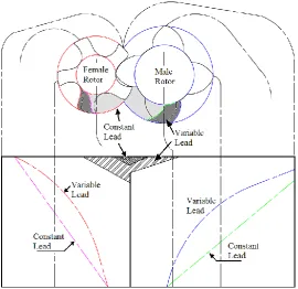
varying the helix lead angle, makes it possible to achieve greater efficiencies. This is illustrated
in Figure 1.11 which shows a comparison between the expected volumetric displacement of
constant and variable lead rotor compressors in machines with otherwise identical dimensions.
Figure 1.11 Comparison of displacement curve
9 | P a g e
Figure 1.13 Cylinder and port development of a rotor pair
It can be seen that with the same rotor wrap angle and suction cut-off volume, the same
built-in volume built-index can be obtabuilt-ined, from variable lead rotors, with earlier openbuilt-ing of the
discharge port. This is also apparent from Figure 1.12 which shows a comparison of the
compression characteristics of the two rotors. As an example for a male rotor with 3 lobes, of
diameter 127.45mm, L/D ratio 1.6 and wrap angle 285°, pairing with a female rotor with 5
lobes, diameter of 120.38mm and discharge ports designed for a 𝑉𝑖 = 1.8, when the male rotor
pitch is varied linearly from 130mm to 40mm the 𝑉𝑖 increases to 2.19 for the same discharge
port and wrap angle.
Throttling loss is the energy lost due to inability of the compressed gas to be readily delivered
and this loss reduces if discharge area is increased. In the case of the variable lead rotors, the
discharge pressure will be reached earlier in the compression chambers. Assuming no over
compression in the working chamber, for the same discharge pressure, the discharge port will
be larger in the case of variable lead rotors. Hence the throttling losses will be reduced.
Figure 1.13 shows the cylinder and port development of a rotor pair. On the end plates the
highlighted areas are the axial discharge ports for a uniform lead and a variable lead rotor and
on the cylinder development, the hatched areas are the radial discharge ports. The axial and
radial ports are timed such that the compression chamber opens to the discharge pressure at a
10 | P a g e
Thus three main advantages of varying the lead on screw rotors can be identified as:
a. Improved compression characteristics. i.e. an increase in the built-in volume index for
a comparable size of rotors.
b. Less throttling losses due to increase in discharge port area for a given pressure ratio.
c. Decreased leakage losses due to reduction in sealing line length towards high
compression zones.
Theoretically the maximum volume of gas that can be sucked into a screw compressor is the
gas region cross-section area multiplied by the rotor length. Any twist on the lobes creates a
material overlap, reducing the fluid volume confined between the inter-lobes and the casing.
Hence if rotor pairs of constant lead, but otherwise identical dimensions, are compared with
variable lead rotors, it is possible that the reduced lead at the discharge end of the rotors may
improve the compression characteristics but, in turn, reduce the suction cut-off volume, thereby
reducing the compressor delivery. This can be a disadvantage of the design. The manufacture
of variable lead rotors is not possible on a commercial scale because the form milling process
adopted for uniform lead rotors is not applicable. The use of the latest technologies like 5-Axis
machine tools is still under investigation but currently such rotors have not been manufactured.
1.4.2 Variable profile parallel axis twin screw compressor
The operating behaviour and advantages, described for variable pitch rotors, can also be
realised if the rotor diameters are made to vary from suction to the discharge. Figure 1.14 shows
an example of a parallel axis variable profile twin screw rotor.
11 | P a g e 1.4.3 Tri-rotor screw compressors
As the pressure difference between suction and discharge is increased in screw compressors,
the rotor root diameter has to increase, in order to be able to endure bending loads and avoid
rotor damage. Also, the number of rotor lobes has to be increased. As a consequence, there is
a decrease in the mass flow rate achieved by a given size of machine.
Figure 1.15 Tri rotor screw compressor
One of the methods of achieving higher mass flows is by running two or more compressors in
parallel. Another approach is to utilize a single male rotor and multiple female rotors to
effectively increase the number of compression chambers and boost the mass flow rate. One
arrangement for two female rotors is shown in Figure 1.15 (Nilsson, 1949). The suction and discharge in this configuration happen on both axial ends of the male rotor and this can help in
reducing the radial load on it. The design of the ports is challenging because the end plates
have to accommodate heavy bearings. This increases the chances of having the full pressure
difference across a clearance leakage path, increasing the effective leakage as compared to just
twin screw arrangement. Such a possibility and also the port design can be investigated further
in detail by CFD analysis.
1.4.4 Single screw compressor variants
Some non-conventional single screw configurations are also available in theory as shown in
Figure 1.16 (Zimmern, 1984). The name convention is based on the form and relative axial arrangement of the gate and main rotors. These are namely: Planar Screw – Cylindrical Gate
(PC type), Cylindrical Screw – Planar Gate (CP type), Planar Screw – Planar Gate (PP type)
and Cylindrical Screw – Cylindrical Gate (CC type). The most widely used arrangement is the
CP type. The CFD analysis of Single Screw Compressors is still unexplored and there are
numerous aspects that may be improved if the detailed physics of flow in these machines is
12 | P a g e
Cylindrical Screw – Planar Gate rotors Planar Screw – Cylindrical Gate rotors
Planar Screw – Planar Gate rotors Cylindrical Screw – Cylindrical Gate rotors
Figure 1.16 Single screw compressor configuration variants
1.4.5 Spiral compressor and expander
In his patent, Perna (2003) described a combination of variable lead, variable diameter mutually interacting rotors. A combination of two of more rotors was included as well as an
integral arrangement for interlobe chamber volume reduction or expansion. A nonparallel axis
of meshing has also been proposed, as shown in Figure 1.17.
13 | P a g e 1.4.6 Internal Conical Rotary Screw Compressor
Recently Vert-Rotors (Vertrotors, 2011) developed a non-classical design of a screw type
compressor with two conical helical rotors of which one is internal and another is external. The
two rotors form a pair of epicycloid /hypocycloid conical screws with a configuration of a 3
lobe internal gear and a 4 lobe external gear, as shown in Figure 1.18. The volume is reduced
during rotation because of the progressive reduction of the rotor diameter. CFD analysis would
help in evaluating the feasibility of obtaining a high pressure ratio in a single stage and in
estimating its performance.
Figure 1.18 Internal twin screw compressor configuration
1.5
Computational methods for fluid flow calculations
General fluid flow is mathematically defined by PDE’s, describing the conservation of mass,
momentum and other scalar quantities of a physical system. These equations are closely
coupled; time dependent partial differential equations, with strong dependence on fluid
properties, and numerical methods are essential for obtaining their solution. A control volume
approach in which the flow within a certain spatial volume is studied is preferred in case of
fluid flow calculations. Numerical methods for fluid flow calculation can be classified using
several features like:
Discretisation method used to approximate the differential or integral conservative
equations into a system of algebraic equations. Time-integration method.
14 | P a g e
Some of the methods are listed below:
Finite Difference method is the oldest method for numerical solution of a PDE’s applicable
for simple geometries. The generic conservation equations are considered in their differential
form as:
𝜕(𝜌 𝜙)
𝜕𝑡 +
𝜕(𝜌 𝑢𝑗 𝜙)
𝜕𝑥𝑗 = 𝜕 𝜕𝑥𝑗 (𝛤
𝜕𝜙
𝜕𝑥𝑗) + 𝑞𝜙 (1.1)
The domain geometry is covered with grid points at which the differential equation is applied.
Partial derivatives in the equation are approximated in terms of the nodal values of the function
at these grid points. The disadvantage of FD formulation is that conservation is not always
enforced.
Finite Volume method, on the other hand, treats the domain geometry as split into a number
of small, regular, contiguous volumes and the centroids of these volumes act as integration
points. The faces of each control volume are shared by adjacent cells. The generic conservation
equations are considered in integral form and hence global as well as local conservation is
15 | P a g e 𝜕
𝜕𝑡∫ 𝜌𝜙𝑑𝛺𝛺 + ∫ 𝜌𝜙𝒗. 𝒏𝑑𝑆 =𝑆 ∫ 𝛤 𝑔𝑟𝑎𝑑 𝜙. 𝒏𝑑𝑆𝑆 + ∫ 𝑞𝛺 𝜙𝑑𝛺 (1.2)
FV formulations can accommodate a variety of cell structures in domain discretisation and
hence are suitable for most of the industrial flow applications.
Finite Element method combines the conservation equation with a weighing function and a
solution is sought such that minimum residuals are attained. The variation of the dependent
function within a control volume called an element is assumed to follow a specified shape
function.
Text such as Tannehill, Anderson and Pletcher (1997), Ferziger and Perić (1996), Versteeg and Malalasekera (1995), Patankar (1980), Date (2005) provide an extensive treatment on the subject of computational fluid dynamics. A variety of numerical algorithms and modelling
practises are available in the literature. Also a number of commercial software packages are
available for flow calculation with these included in many real world industrial applications.
Even the process of grid generation has matured enough to the point where physicists can use
commercially available tools directly and generate the type or size of grid required for an
application. The situation for applications like screw machines is not so favourable. Given the
complexity of the fluid geometry, the grid requirements are much more stringent and hardly
any commercially available grid generator has been found suitable for these applications
(Kovačević, 2002). Under these constraints and also due to the nature of the governing equations, that need to be solved when the computational domains deform with time, FV
methods are most suitable for screw machine numerical flow calculations.
Discretisation methods are used to approximate the differential or integral conservative
equations into a system of algebraic equations. In the FV method this discretisation is the
division of the physical computational domain into small non-overlapping discrete volumes
that share faces and together represent the grid of the geometry with all boundaries. These
volumes are used for the solution of the conservation equations and it is important that the grid
achieves the desired cell type and quality required for accurate solution of the numerical
method employed.
1.6
Grid generation approaches in practise
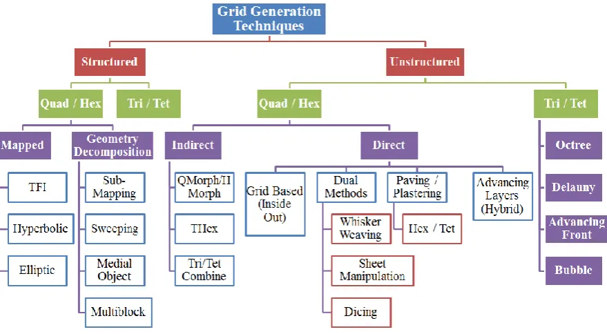
Figure 1.19 shows a breakdown of some of the basic grid generation techniques in practise
today. They are broadly dependent upon the type of grids required and the grid data structure.
16 | P a g e
grids are preferred from consideration of solver accuracy and discretisation, but it is difficult
[image:36.595.80.520.121.363.2]to generate structured grids in complex practical geometries using common algorithms.
Figure 1.19 Basic grid generation techniques
Unstructured grids with tetrahedral geometry have been the most successful because of their
ease of generation and adaptation, even in complex geometries but they suffer from lack of
high accuracy, solution instabilities and a high cell count compared to hexahedral geometry
grids. Based on the cell geometry, grids can be classified as Quadrilateral, Hexahedral,
Triangular, Tetrahedral, Prism, Pyramid or Polyhedral (not shown in Figure 1.19). It is also
possible to construct a hybrid structured-unstructured grid with a combination of different cell
geometries as suitable in a particular region of the computational domain.
Such methods of grid generation are widely applied in commercial grid generators for FV
formulations. When the geometry of a twin screw compressor’s working chamber or other types of screw machine’s working chambers is considered, the grid has to deform in operation
and also needs to capture the large variation in the size of the domain from core flow region to
the leakage flow region in clearances. Due to these reasons, commercial grid generators have
not been successful in producing deforming grids for screw machine flow domains. Out of the
techniques presented in Figure 1.19, structured methods with mapped topologies and using TFI
or Elliptic solutions have been possible when implemented into customised grid generation
17 | P a g e
attempted in practise. The literature review, presented in Section 2.2, presents some studies
using these methods.
1.7
Motivation to investigate grid generation in numerical methods
The objective of using CFD models for analysing flow in screw machines is to get complete
details of the flow field and trace sites where designers can improve the dynamics of the fluid
flow. Such information is not available from classical methods of modelling such as chamber
analysis. With the available technology, CFD analysis of dry running twin screw compressors
and expanders has been made possible. This was mainly achieved due to the introduction of
customised grid generation tools and commercial solvers capable of integrating seamlessly
with them.
The motivation for this research has been twofold in this respect.
The methods of grid generation currently used for deforming rotor domains have been
developed for uniform rotor geometry and parallel axis alignment. When it comes to the
analysis of new variants of design such as those described in Section 1.4, there are still
many challenges in constructing a CFD model. This is because the customised grid
generation tools are not generic in nature and need further modification when the basic
rotor or compression chamber designs change. Hence it was necessary to develop new
procedures of grid generation for rotors with variable geometry.
With the approach for screw rotor grid generation in which the node distribution on the
rotor profiles is fixed, there are two features of the grid that require attention.
a) The interface between the two O blocks is Non-Conformal
b) At the CUSP points there exist nodes that are merged with other nodes.
Figure 1.20 shows an example of a non-conformal interface between the two rotor blocks.
Such a grid is generated when completely discontinuous O Blocks are constructed. They
give flexibility to improve the cell quality in the individual blocks by orthogonalisation and
smoothing and at the same time improve the robustness of the control parameters used for
profile adaptation and distribution regularisation, but the presence of a non-conformal
interface raises concerns about the stability of the solver and quality of flux balance that
will be achieved with any additional physical equations, as in oil injection or water cooling.
Moreover not all solvers are capable of defining an interface with such high node
18 | P a g e
Figure 1.20 Non-conformal interface between the two rotors
Similarly the reason for having nodes merged at the CUSP points is to capture a straight
line in the axial direction and the blow-hole area accurately as shown in Figure 1.21.
Figure 1.21 Merged nodes at the CUSP point to capture blow-hole
This results in the creation of Pyramid or Prism cell topology at the CUSP’s. This is not an
error, because the conservation equations are solved by the solver treating the respective
element topologies. However there are some solvers like ANSYS FLUENT, STAR CCM+
that result into degenerated cells when the nodes are merged during the solution.
Hence it was necessary to develop or try other possibilities of grid generation in the rotor
cross section such that these grid quality features could be improved.
Accordingly this study was focused on the development of grids for variable geometry rotors
and device improvements in the cross section grids being finally used to construct a three
19 | P a g e
Chapter 2
– Literature Review
Screw machines have been traditionally designed using thermodynamic lumped parameter
models. These models have remarkably helped in the evaluation of the machine performance
and for optimisation of rotor profiles for a given application. A lot of literature is currently
available that focuses on such lumped parameter models. Some of the research published in
the area has been discussed here. These studies have highlighted the capabilities that can be
achieved by a simplified model and also the important physical phenomenon that have been
idealised and need to be accounted by higher order numerical flow models.
The main sources of literature have been the three major international conferences dedicated
to compressor technology. These are:
International Compressor Engineering Conference held at Purdue University, USA. International Conference on Screw Machines held at TU Dortmund, Germany.
International Conference on Compressors and their Systems held at City University London, UK.
Apart of these conferences there are many journals like the International Journal of Refrigeration that have regularly provided technological updates on Screw machine systems. A large number of Patents have been published on rotor profiles, flow control systems and
rotor configurations like twin screw or multi screw arrangements. A few good books have also
been published on Screw machine technology, such as those of Sakun (1960), Andreev (1961) and Amosov (1977) in Russian, Rinder (1979) and Konka (1988) in German, Xing (2000) in Chinese and by O’Neill (1993), Arbon (1994) and Stošić et al. (2005a) in English. More recently, 3D numerical models employing CFD have been investigated and a few papers have
been published in these conference proceedings. Only one book by Kovačević et al. (2007) is available, which is focused on the CFD analysis of twin screw machines while a few journal
papers are available presenting screw machine grid generation technology.
In this chapter, the practise and application of Computational Fluid Dynamics for screw
machines has been critically reviewed. Modelling approaches published in some of the journals
and conferences and typical results achieved have been highlighted. Special attention has been
given to grid generation techniques. A detailed review of the algebraic and differential
20 | P a g e
algebraic approach of grid generation, the PhD thesis by Kovačević (2002), the monograph by
Kovačević et al. (2007) and associated technical papers have been the primary source. For the differential approach of grid generation, the PhD thesis by Vande Voorde (2005) and associated technical papers have been the primary source.
Form the available techniques for deforming grid generation it was found that Arbitrary
Lagrangian Eulerian (ALE) formulations with customised grid generation tools have been
successfully used for twin screw machines. A comparatively new approach of Key-Frame
remeshing is available with commercial flow solvers and has been investigated in Section 4.4
for its accuracy and applicability to screw machines.
The review of available literature and CFD practises have confirmed the need for further
development of numerical models and grid generation techniques for screw machines.
Presently available approaches of grid generation need to be extended to produce better quality
computational cells and also make them suitable for non-conventional screw machines like
variable geometry rotors.
2.1
Numerical analysis of Screw machines using lumped parameter models
For oil free or oil injected twin screw compressors, Fujiwara et al. (1974, 1984), Fujiwara and Osada (1990), Fukazawa and Ozawa. (1980), Sangfors (1982 and 1984), Singh et al. (1984 and 1990), Dagang et al. (1986), Kauder and Rau (1994) and Janicki (2007) presented numerical models. These were based on the classical approach of solving the equations of
conservation of mass and energy applied to a control volume. The use of uniform parameter
values, within the whole volume, enabled ordinary differential equations to be used. Because
of the coupled nature of these equations, they could not be solved analytically and a numerical
approach had to be adopted. The challenging part of the modelling has been to calculate
accurately the geometric properties of the machine, such as the change in volume with time
and estimation of the various leakage gaps.
Stošić and Hanjalić (1977) developed models, by solving numerically the internal energy and mass conservation differential equations using Runge – Kutta fourth order procedure and this
was applied to calculate the performance of two stage reciprocating compressors. In 1988 the
procedure was extended and implemented in the program SCORPATH© - Screw Compressor