Abstract. Estimating the spatial coordinates of nodes is one of the research challenges in Wireless Sensors Networks (WSN). Localization problem deals with the identification of the sensor node’s position. Localization is a primary task for data dissemination, object tracking, routing etc. All these applications are location dependent. This work aims at identifying the physical coordinates of nodes in the network by providing minimal localization error and thereby increasing localization accuracy. Mobile Anchor-based positioning, a range–free localization method used for localization of the nodes. The proposed algorithm used for localization is Jumper Firefly Optimization Algorithm through Mobile Anchor Positioning (JFA-MAP). The objective is to apply JFA – MAP algorithm over the results of MAP with Mobile Anchor & Neighbor (MAP-M&N) to improve the location accuracy. Based on Root Mean Square Error (RMSE), the experimental analysis was performed, and simulation studies convey that the proposed JFA-MAP approach is efficient in reducing the localization error than MAP-M&N algorithm.
Keywords: Mobile Anchor, Jumper Fire fly, RSSI,MAP
I.INTRODUCTION
In WSNs, sensor nodes are positioned in an unmanned area to sense the physical phenomena such as temperature, humidity, moisture level, intrusion of an object of interest in a remote location. Nodes in the network are connected through wireless communication. Some of the design challenges in sensor nodes include limited computational capability, low energy, connectivity issues and scalability. Nodes in the network need to share the sensed information along with their position information. Location identification of sensor node is significant to estimate the position of neighboring nodes for the applications like target tracking, data dissemination, routing, rescue operations etc. Inaccurate position information propagates to several nodes, leads to imprecise physical coordinate information computation. This results in localization error which is not desirable for position-based applications. This factor has motivated the researchers to work on localization problem.
The purpose of localization is find the physical location of nodes which is deployed in a region to sense the environment.
Revised Manuscript Received on May 28, 2019.
Dr.S. Sivakumar, Department of Electronics and Communication, Presidency University, Bangalore,India.
Email: [email protected]
C.Bharathi Priya, Department of Computer Science & Engineering, Kumaraguru College of Technology, Coimbatore, India.
Email: [email protected]
Localization process consists of two phases: distance estimation and location computation. Distance estimation techniques are based on the computation of estimating the relative distance between nodes. Position computation algorithm manipulates the relative distance to compute the location of nodes which do not know its physical location. Localization of nodes must reduce the error in computing location and must be precise.
In localization process, the nodes can estimate its position based on anchor node or beacon node or Landmark Nodes (LN). Anchor or Beacon node knows its location through location service such as Global Positioning System (GPS). These nodes aware of its location, hence termed as location aware nodes. Localization algorithm can be a range based or a range free algorithm [5]. Range based algorithm, based on received signal strength or angle to compute the relative distance from the beacon node. Through this absolute distance or estimated angle, unknown nodes approximate the location of its position based on anchor nodes. Range based techniques need extra hardware such as antenna or GPS to receive the signal.
Range free techniques are based on the messages exchanged between nodes to achieve coarse grain accuracy. The main part is localization, which deals with MAP. MAP utilizes the beacon packets exchanged between landmark nodes and neighboring nodes to locate the spatial coordinates of the unknown nodes. Beacon packets consist of physical coordinate and its unique ID. Mobile anchor nodes are provisioned through Global Positioning System (GPS), which transmits its physical positions to the neighboring nodes as it traverse around the sensor network. Nodes in the network receive the beacons to compute their locations locally. Privacy and security is also a crucial factor in this location awareness process.
Hence, idea of localization is to identify the spatial coordinates of a set of sensors deployed in the network. Since the senor nodes deployed in the environment is massive, use of GPS for many anchor nodes is costlier; hence sensor nodes in the network need to self-organize a coordinate system. GPS satellite signals would be weakened in indoor environment than cellular system signals. It does work very well in an urban environment.
Localization scheme can be classified as range-based and range-based techniques. Received Signal Strength Indicator (RSSI) is a range-based
localization scheme [6] based on received signal
strength at the
S. Sivakumar, C.Bharathi Priya
sender/receiver side, Time Difference of Arrival (TDoA) [7], Time of Arrival (ToA) [8] and Angle of Arrival (AoA) [9]. Former techniques is uses distance/angle parameter and is suitable for indoor location geometric principles.
Range free localization makes use of connectivity information or pattern matching method to measure the location. Distance can be measured directly using hop counts. Once if hop counts are obtained, distances between nodes are computed, the average distance per hop is computed based on the distances between two nodes and then geometric principles are used to calculate its location.
After estimating the node’s location using mobile anchors, the proposed meta-heuristic approach, optimization algorithm with localization algorithm is applied. Using Range free localization approach, anchors broadcast its location information during movement and rest of the neighboring nodes estimates it location and JFA-MAP is applied to obtain the optimized localization result.
The paper is structured in the following manner: Section I deals with categories of localization algorithm. Section II elaborates the literature of proposed Jumper Fire Fly Optimization algorithm with Mobile Anchor Positioning (JFA-MAP) algorithm, Section III discusses the proposed algorithm and Section IV compares the simulation results with the existing algorithm and proposed meta-heuristic algorithm. Section V gives the summary of the proposed work.
II. RELATED WORK
In this section, a review on localization techniques to find the spatial coordinates of the nodes in remote location is given. Classes of localization mechanisms are range-based and range-free localization. [13] proposed Mobile Anchor Positioning (MAP), anchor nodes in the network obtains spatial information, termed as Beacon packet. Sensor nodes in the communication range would collect beacons from the anchor , when the anchor node moves around the sensing field. Each node after receiving beacons forms two circles with chosen beacon as radius of the circle. Radius of the circle defines the communication range of the sensor node. Based on decision strategy, one of the two points is chosen to be the location of the sensor node.
Pan et al [11], proposed a multi-objective optimization algorithm for location estimation which uses objective functions by considering geometric topology of the node’s sensing field and distance of the nodes.
In this work, Jumper Firefly with Mobile Anchor Positioning (JFA - MAP) Algorithm, range free localization algorithm is proposed. Using Mobile Anchor Positioning (MAP), location of nodes can be approximately computed. Jumper Firefly, is an evolutionary strategy, is applied over MAP to obtain the results with less error. It is observed that JFA-MAP, estimated location of the nodes provides accuracy better than MAP.
Sivakumar et al [15] have proposed MAP-M&N with three meta-heuristic approaches, to compute the location of nodes with very minimal error. FOA is applied over MAP-M&N and RMSE metric is used to evaluate the performance with MAP-M&N algorithm.
III. PROPOSED APPROACH
The proposed algorithm is to estimate spatial location of nodes and by using optimization algorithm, it must minimize the localization error. It consists of two phases: 1) Using Mobile Anchor Positioning (MAP), range free algorithm, each node estimates its distance through anchor nodes. In the second phase, Jumper fire fly Optimization algorithm is executed over the output of MAP. Results obtained from MAP are fine-tuned by this optimization algorithm to achieve the maximum localization accuracy.
Mobile Anchor Positioning (MAP)
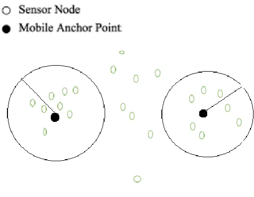
[image:2.595.307.562.383.581.2]Sensor Network has several sensor nodes which are arbitrarily installed in the unmanned remote location. Few nodes are designated as anchor nodes (also termed as land mark nodes) which is aware of its physical coordinate. Each node has certain range for sensing and communication, termed as sensing field and communication range respectively. Nodes may be static or dynamic, depending upon the application of deployment. Nodes can receive information from other neighboring nodes and /or from anchor nodes.
Fig.1. Sensor node Environment
Mobile anchor points equipped with GPS to receive the latitude and longitude information and the basic assumption is anchor nodes have adequate energy to navigate and broadcast beacon information to the nodes in the sensing field. Mobile anchor nodes may be mounted on vehicles which may be carried or by robots. They move in a certain speed and direction for specific time and remain stationary for certain time. During this period, anchor node passes the beacon packets to the nodes in the communication range.
nodes which do not know its physical coordinate and m anchor nodes, knows its physical coordinate. Sensor nodes are arbitrarily distributed in the environment; anchor node can transmit the beacon information to its communication range r. Nodes within the range r, obtain the beacon packets from one or more beacon nodes and estimate its position.
Beacon points
Approximate location of sensor node.
Beacon packets
Fig.2. Probable spatial positions of nodes
In Fig 2, two beacons (T1, T4), which are far away from each
other, are Beacon points. T1, T4 are communication range of
the sensor node,it receives the beacon packet from anchor. Hence T1 and T4 represent beacon points that may fall either
in two locations of the same anchor or two different anchor nodes. These nodes are in the sensing region indicated by dotted circle.
S’and S’’ are the meeting points of both circles, these overlapping points are the sensing regions of the sensor node. Meeting points can also be termed as intersection points. Beacon points (T1, T4) are considered as extreme points of
range r. Beacon node with radius R, will have the communication range r, anchor node positioned in the center and node would be in the boundary of the circle.
Location Identification using range free technique: Following assumptions are considered for location identification. Each sensor node maintains a visitor list to record the mobile anchor nodes visiting its sensing region. This scheme uses MAP-M to record the beacon packets received from the anchor nodes. Node n1, has visitor list T1,
T2,..Tn. Communication range is r, intersection points of the
circle are S′ and S′′.
Steps to locate the node are explained as follows:
1. Intersection of points between T1 and Tn is considered as
beacon point.
2. If Ti (2 ≤ i≤ n21), € distance between Ti and S′ < R
&&Ti -S′′ > R, Position of unknown node= S′.
3. Certainly, beacon point is covered by the shaded area, distance between unknown node and location from which beacon packet has come=S′ and S′′ < R. Location cannot be determined
4. If beacon packets fall out of the shaded area, then node S would not estimate the location. Hence, the node retains S′ and S′′ as the two possible locations.
Fig.3. Shadow Region between T1 and T4
It is evident from this study that, appropriate location of node cannot be determined by means of beacon packets, hence node needs to wait to get furthermore beacon packets. If beacon packets does not reach the unknown node, position of the node cannot be computed.
Visitors list, is a data structure, consists of the list of anchor nodes who have broadcasted beacon packets. It is maintained by each node after obtaining beacon packets from the mobile anchor. Visitor list of S consists of position information which is represented as{T1,T2...Tn}.In fig 3, T1 and T4 are
considered as two extreme points i.e.,T1 and Tn. These
coordinates are referred as extreme points, these beacon points are the first and last point in the visitor list.
Fig.4. Visitor node information from adjacent nodes
If the node has couple of locations S' and S”, if it obtains another beacon packet from
another anchor node, it calculates the distance. But if the unknown node does
v
v
T
1
T
2
T
3
S’
T
4
not obtain any beacon packet further, then the position cannot be determined. To alleviate this problem, Mobile Anchor Positioning with Mobile Anchor & Neighbor (MAP-M&N) method is used. Fig 4 specifies the visitor node information from adjacent nodes.
Beacon/Anchor points falls in the shaded region, determining the location of sensor node is not possible.
Sensor Location identification with MAP - M&N: In this scheme, it is assumed that some of the nodes have estimated its location using anchor nodes. Nodes which have obtained its location from mobile anchor nodes are referred as settled nodes. Settled nodes would flood its physical coordinate information to one hop distance nodes, in this way settled nodes assists unknown nodes to determine its position which are one hop away.
Steps to determine the spatial position of sensors in the environment using MAP – M & N method is given in the following section:
1.
N Sensor nodes are installed in a region of m* m and few anchor nodes are equipped with GPS.2.
The landmark nodes traverse arbitrarily in the deployed area and periodically broadcast its physical location as beacon packets.3. Every node in the network upholds a visitor list which has beacon packets broadcast by mobile anchors nodes.
4. Beacon packets may be received by unknown nodes with the farthest point and select the packets as extreme or beacon points.
5.
Identified beacon points are considered as the centers, it is the region of communication of a sensor node with radius R, with this information two circular areas are built to compute the meeting points.6. Unknown node estimates its position using these intersection points. It is expected at least to have one beacon point falls outside the shadow region. Otherwise, one beacon point information must be received from neighboring nodes.
Jumper Firefly optimization algorithm with Mobile Anchor Positioning (JFA-MAP): This is an optimization algorithm, the meta heuristics algorithms [14] are computationally efficient than the analytical solutions. The purpose of this algorithm is to obtain the optimal position of unknown nodes by minimizing the localization error. JFA is applied after MAP; main objective is to localize many unknown nodes with minimal localization error. When the number of iteration increases, number of localized nodes also needs to be increased. Algorithm is defined as follows:
Algorithm: Jumper Firefly optimization algorithm Following steps are considered to estimate the sensors in the environment using JFA-MAP algorithm:
1. Output of MAP-M&N, has certain localized nodes with estimated location of each sensor node. Results of Mobile Anchor Positioning (MAP-M&N) are given as input. 2. Jumper Firefly is applied to each sensor node for computing the accurate location.
3. For each iteration and for every firefly fitness value is computed. Fitness function is obtained by finding the variance in computed position with rest of the flies.
4. At each iteration, each firefly is considered one at a time and compared with rest of the flies to calculate their fitness calculation.
5. Movement of a firefly xi is calculated as stated in equation
(1):
= + (1)
6. Steps 3 to 5 is applied for each firefly and JFA with maximum fitness is selected for next iteration
7. The algorithm terminates until it reaches the maximum profit value or maximum iteration count.
IV. SIMULATIONRESULTS
The following set of parameters is considered for simulation in NS2 environment. Number of anchor nodes, velocity of mobile landmark nodes, set of unknown nodes with different computation time and the experimental outcomes were examined. Choice of routing protocol and mobility model are AODV and Random way-point mobility model respectively. It is observed from various simulation studies, that the parameters given below are optimal for in terms of localization error.
Table I: Parameter set for simulation
Parameters Value
Sensing region 1000 m X 1000 m
Nodes deployed 100
Number of anchor nodes 3
Velocity of landmark nodes 100 m/sec
Time interval 1 sec
Computation duration 500 sec
Transmission range 250 m
Routing Protocol AODV
MAC Protocol IEEE 802.11
Mobility Model Random way-point
Metric used in determining the Localization Accuracy Root Mean Square (RMSE) metric is found to be suitable to evaluate the accuracy of locations estimated by JFA & MAP. Location accuracy is verified by calculating RMSE for MAP-M&N and proposed JFA-MAP using the equation (2) as stated below:
R … (2)
, coordinates of the sensor node
Assessment of RMSE computed using MAP-M&N and JFA-MAP approaches.
Performance Analysis: MAP-M&N and JFA-MAP algorithm is experimented with the parameters tabulated
above and their performance is measured in terms of location accuracy. RMSE is computed for the following: MAP-M&N and JFA-MAP approaches and it can be learnt from this analysis that RMSE is less than MAP-M&N.
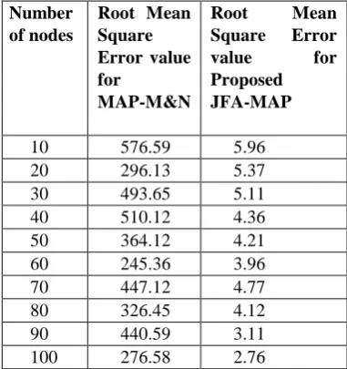
Table II: Error Calculation for JFA-MAP algorithm and MAP-M&N algorithm
Number of nodes
Root Mean Square Error value for
MAP-M&N
Root Mean
Square Error
value for
Proposed JFA-MAP 10 576.59 5.96 20 296.13 5.37 30 493.65 5.11 40 510.12 4.36 50 364.12 4.21 60 245.36 3.96 70 447.12 4.77 80 326.45 4.12 90 440.59 3.11 100 276.58 2.76
[image:5.595.360.551.149.352.2]Number of nodes is increased from 10 in every iteration, JFA-MAP based localization is applied and from the simulation results, it is learnt that value of RMSE is reduced for JFA-MAP. In this experimental analysis, it is evident that there is an raise in RMSE value for the number of nodes from 60 to 70. Random way-point mobility model is used for node mobility and every time the simulator randomly places the node in new positions and localization is applied to that environment. Figure 5, illustrates the Comparison graph for RMSE in MAP-M&N and JFA-MAP approaches.
[image:5.595.302.563.501.842.2]V. CONCLUSION
In this paper, Jumper firefly optimization algorithm has been proposed along with Mobile Anchor Positioning for localizing the sensor nodes. Even though the percentage of located nodes is high in MAP-M&N algorithm but it does not provide fine-grained accuracy. Hence an optimization algorithm named JFA-MAP has been applied for localizing sensor nodes to minimize the error during localization. Simulation results based on RMSE convey the fact that JFA-MAP algorithm significantly reduces the localization error on an average by 99.5%, which is far better than MAP-M&N. Further to minimize the error during localization process, hybrid optimization algorithm such as Genetic Firefly Optimization Algorithm can also be applied along with mobile anchor positioning and compared with JFA-MAP algorithm.
REFERENCES
1. J. Bachrach, C. Taylor.: Localization in Sensor Networks, Handbook of Sensor NetworksAlgorithms and Architectures, Hoboken, NJ, John Wiley, pp. 277-310,(2005)
2. G.Mao,B. Fidan , B.D.O.Anderson .:Wireless Sensor Network Localization Techniques ,Elsevier Science B.V. Publishers, Computer Networks ,vol.51, no.10, pp. 2529-2553,(2007)
3. A. Hashmi, N. Goel, S. Goel, D. Gupta:.Firefly Algorithm for Unconstrained Optimization,IOSR Journal of Computer Engineering (IOSR-JCE), vol. 11, pp. 75–78, (May-June 2013).
4. M. Bidar ,H. R. Kannan.: Jumper firefly algorithm.: International Conference on Computer and Knowledge Engineering (ICCKE-2013), pp. 267–271, (2013).
5. Van-Oanh Sai, Chin-Shiuh Shieh.: Parallel Firefly Algorithm for Localization Algorithm in Wireless Sensor Network, Third International Conference on Robot, Vision and Signal Processing (RVSP) ,(2015).
6. Pengfei Peng, Hao Luo, Zhong Liu, and Xiongwei Ren.: A cooperative target location algorithm based on time difference of arrival in wireless sensor networks, Proc. of the Int. Conf. on Mechatronics and Automation (ICMA 2009), pp. 696-701, (2009).
7. Guowei Shen, Zetik R, Honghui Yan, Hirsch O, and ThomasR.S.: Time of arrival estimation for range based localization in UWB sensor networks, Proc. of the IEEE Int. Conf. on Ultra-Wideband (ICUWB 2010), vol. 2, pp. 1-4 ,(2010).
8. Y. Zhu, D. Huang, and A. Jiang.: Network localization using angle of arrival, Proc. of the IEEE Int. Conf. on Electro/Information Technology (EIT 2008), pp. 205-210, (2008).
9. G.Yu, Fengqi Yu, and L. Feng.: A localization algorithm using a mobile anchor node under wireless channel,‖ Proc. of IEEE Int. Conf. on Robotics and Biomimetics,(2007) .
10. B.Pei, H. Zhang, T. Wan.: Firefly Algorithm Optimization Based WSN Localization Algorithm, IET,(2015) .
11. T Nguyen, J Pan, S Chu, Roddick, T Dao. Optimization Localization in Wireless Sensor Network Based on Multi-Objective Firefly Algorithm, Journal of Network Intelligence,Volume 1, (2016) .
12. Yurong Xu, Yi Ouyang, Zhengyi Le, James Ford, F Makedon.: Mobile Anchor-free Localization for Wireless Sensor Networks, International Conference on Distributed Computing in Sensor Systems, DCOSS
2007: Distributed Computing in Sensor Systems pp. 96-109, (2007) 13. W.-H. Liao,Y.-C. Lee, S.P. Kedia.: Mobile anchor positioning for
wireless sensor networks”, IET, Vol 5,Iss 7,PP 914-921,(2011). 14. Chandrasekaran D, T. Jayabarathi.: Wireless Sensor Networks
Node Localization-A Performance Comparison of Shuffled Frog Leaping and Firefly Algorithm in LabVIEW,
TELKOMNIKA Indonesian Journal of Electrical Engineering, Vol. 14, No. 3, pp. 516 – 524, (2015).
15. S. Sivakumar, R. Venkatesan.: Meta-heuristic approaches for minimizing error in localization of wireless sensor networks, Applied Soft Computing, Elsevier, vol.36, pp.506-518, (2015).
16. N.V.S.N Sarma, Mahesh Gopi.: Energy Efficient Clustering using Jumper Firefly Algorithm in Wireless Sensor Networks, International Journal of Engineering Trends and Technology (IJETT) – Volume 10 Number 11,(2014).
AUTHORSPROFILE
Dr.S.Sivakumar, Associate Professor in Department of Electronics and Communication at Presidency University, Bangalore .He has completed both BE (ECE) and ME in Communication Systems from Kumaraguru College of Technology (KCT), Coimbatore. He has 16 years of teaching experience in PSG College of Technology, Coimbatore and 1 year Industrial experience as Design Engineer at Pricol Technologies, Coimbatore . His research domains are Sensor networks, IoT, Evolutionary Computing and Digital Signal Processing. Currently he is serving as a Journal paper reviewer for International Journal of Distributed Sensor Networks-Hindawi, IJCT, IAENG International Journal of Computer Science and IET Communications from the year 2016
C.Bharathi Priya received the Post-Graduation in Computer Science from University Of Mysore, Karnataka, India and her UG specialization is B.E (Information Technology) ,received from Bharathiar University, Tamilnadu. At present she is working as an Assistant Professor ,Department of Computer Science at Kumaraguru College of Technology. She has 14 years of teaching experience in handling computer science/IT related subjects and approximately 2 years of experience in Industry. She has handled various projects related to Medical Image Processing and offered IOT based solutions for real time applications. She is pursuing Ph.D. in the domain of Wireless Sensor Networks and Wind Energy analytics. Her research interests include Wireless sensor networks, Data analytics, IOT and Image Processing.