UNIVERSITI TEKNIKAL MALAYSIA MELAKA
DEVELOPMENT OF ELECTRONIC COMPONENT RACK
SYSTEM BY USING PIC
This report is submitted in accordance with the requirement of the Universiti Teknikal Malaysia Melaka (UTeM) for the Bachelor of Electronic Engineering
Technology (Industrial Electronic) with Honours.
by
SHARIFAH NURUL JANNAH BINTI SYED MOHD FADZIL B071410658
930617-01-6012
FACULTY OF ENGINEERING TECHNOLOGY
UNIVERSITI TEKNIKAL MALAYSIA MELAKA
BORANG PENGESAHAN STATUS LAPORAN PROJEK SARJANA MUDA
TAJUK: Development of Electronic Component Rack System Using PIC
SESI PENGAJIAN: 2016/17 Semester 2
Saya SHARIFAH NURUL JANNAH BINTI SYED MOHD FADZIL
mengaku membenarkan Laporan PSM ini disimpan di Perpustakaan
UniversitiTeknikal Malaysia Melaka (UTeM) dengan syarat-syarat kegunaan seperti berikut:
1. Laporan PSM adalah hak milik Universiti Teknikal Malaysia Melaka dan penulis. 2. Perpustakaan Universiti Teknikal Malaysia Melaka dibenarkan membuat salinan
untuk tujuan pengajian sahaja dengan izin penulis.
3. Perpustakaan dibenarkan membuat salinan laporan PSM ini sebagai bahan pertukaran antara institusi pengajian tinggi.
4. **Sila tandakan ( )
SULIT
TERHAD
TIDAK TERHAD
(Mengandungi maklumat yang berdarjah keselamatan atau kepentingan Malaysia sebagaimana yang
termaktub dalam AKTA RAHSIA RASMI 1972)
(Mengandungi maklumat TERHAD yang telah
ditentukan oleh organisasi/badan di mana penyelidikan dijalankan)
AlamatTetap:
NO 20 Jalan Lorong Lembah Murni, Permatang 7, Kg Kempas Baru 81200 Johor Bahru
Tarikh: ________________________
Disahkanoleh:
Cop Rasmi:
Tarikh: _______________________
** JikaLaporan PSM ini SULIT atau TERHAD,
DECLARATION
I hereby, declared this report entitled “DEVELOPMENT OF ELECTRONIC COMPONENT RACK SYSTEM USING PIC” is the results of my own research
except as cited in references.
Signature : ……….
Author’s Name : SHARIFAH NURUL JANNAH BINTI SYED MOHD FADZIL
APPROVAL
This report is submitted to the Faculty of Engineering Technology of UTeM as a partial fulfillment of the requirements for the degree of Bachelor of Electronic Engineering Technology (Electronic Industry) with Honors. The member of the supervisory is as follow:
MR EFFENDY ONN BIN SIAM (Project Supervisor)
i
ABSTRAK
ii
ABSTRACT
iii
DEDICATION
Alhamdulillah, praise to be Almighty Allah S.W.T. As well as everything that I do, I would be honour to dedicated this thesis to my beloved mother that gave the tools
and value necessary to be where I am standing today Jamaliah Binti Md Yassin. To my siblings
Syed Mohd Fakhrullah bin Syed Mohd Fadzil Syed Mohd Fakhri bin Syed Mohd Fadzil Sharifah Nur Jalilah binti Syed Mohd Fadzil
Syed Mohd Fauzan bin Syed Mohd Fadzil
To my supervisor,
Mr. Effendy Onn bin Siam, for their guidance and encouragement To my co-supervisor,
Mr. Mohd Anuar bin Adip, for their counsel To my fellow friends
iv
ACKNOWLEDGEMENT
Bismillahirrahmanirrahim
In the name ofAllah S.W.T,the mostcompassionate andthe most merciful.
Firstly, thanks to Allah S.W.T as a result of giving me a good health and big spirit and strength to try and do this final year project II.
Secondly, I would wish to express my deepest appreciation to all or any people who provided me to chance to finish this report. A special feeling I give to our final year project supervisor, Mr. Effendy Onn bin Siam, whose contribution in stimulating suggestions and encouragement, helped me to coordinate my project particularly in writing this report.
v
TABLE OF CONTENT
Abstrak i
Abstract ii Dedication iii
Acknowledgement v
Table of Content vi
List of Tables vii
List of Figures ix
List Abbreviations, Symbols and Nomenclatures xi
CHAPTER 1: INTRODUCTION 1
1.0 Introduction 1
1.1 Background of the study 1
1.2 Problem Statement 2
1.3 Objective 2
1.4 Scope Project 3
1.5 Thesis Outline 4
CHAPTER 2: LITERATURE REVIEW 5
2.0 Introduction 5
2.1 History Rack System 5
2.2 Previous Development of Rack System 6
2.2.1 Development how to Store and Organize Electronic Part Using Arduino 6
2.2.2 Voice Controlled Robotic Component Finder 6
2.2.3 Automated Storage for Electrical Component 7
2.3 Comparison Between Different Rack Storage Technologies 7
2.4 Summary of Previous Project 8
vi
2.5.1 Microsoft Visual Studio 9
2.5.2 Microsoft Access 10
2.5.3 Micro C Pro for PIC 11
2.6 Hardware Overview 11
2.6.1 Microcontroller 12
2.6.2 434MHz RF Transceiver Module UART (100m) 13
2.6.3 USB UART 14
CHAPTER 3: METHODOLOGY 15
3.0 Introduction 15
3.1 Project Implementation 16
3.2 Project Planning 18
3.3 Project Flow 20
3.4 Hardware Selection 21
3.5 Software Implementation 23
3.5.1 Set up Micro C Pro for PIC 24
3.5.2 Create Form using Microsoft Visual Studio 26
3.5.3 How to Connect Database 34
3.6 Hardware Development 38
3.6.1 Hardware Block Diagram 38
3.6.2 Schematic Diagram 39
CHAPTER 4: RESULTS AND DISCUSSIONS 41
4.0 Introduction 41
4.1 Software Development Results 41
4.2 Hardware Development Results 45
4.2.1 PIC Circuit 46
4.2.2 Project Working 46
4.3 Results Observation 48
4.3.1 Rack System 48
4.3.2 Manual 49
vii
CHAPTER 5: CONCLUSION AND RECOMMENDATION 52
5.0 Introduction 52
5.1 Conclusion 52
5.2 Recommendations 53
REFERENCES 54
APPENDIX 55
A. Coding Micro C Pro 55
B. Coding Microsoft Visual Studio 59
viii
LIST OF TABLES
2.1 Advantage & Disadvantage of Rack Storage that has been developed
8
3.1 Gantt Chart PSM I 18
3.2 Gantt Chart PSM II 19
3.3 Main Hardware Selection 21
4.1 Results Rack System 48
4.2 Results Manual 49
ix
LIST OF FIGURES
2.1 Microsoft Visual Studio 9
2.2 Microsoft Access 10
2.3 Micro C PRO for PIC 11
2.4 PIC 18F45k22 12
2.5 434MHz RF Transceiver Module (UART) 13
2.6 USB UART 14
3.1 Flowchart for the overall project 17
3.2 Project Flow 20
3.3 Flow Chart Software 23
3.4 Check Port Com 24
3.5 USART Terminal 24
3.6 Choose Port Com 25
3.7 Connect the Icon 25
3.8 Sent Data 26
3.9 Visual Studio downloaded 27
3.10 Create New File 27
3.11 Choose Toolbox 28
3.12 Design Form 28
3.13 Program TextBox 29
3.14 Change Background 29
3.15 Form 1 Login 30
3.16 Insert Library 30
3.17 Form 2 31
3.18 Form 3 31
3.19 Form 4 32
3.20 Form 5 32
3.21 Form 6 33
x
3.23 Form 8 34
3.24 Form 9 34
3.25 Serve Explorer 35
3.26 Add Connection 35
3.27 Change Microsoft Access Database File 36
3.28 Test Connection 36
3.29 Connection Database1.mdb 37
3.30 Copy Connection String 37
3.31 Paste the Link 38
3.32 Hardware Block Diagram 38
3.33 Schematic Diagram 39
4.1 Registration 42
4.2 Log In 42
4.3 User Approval 43
4.4 User Approve 43
4.5 Delete User 44
4.6 Admin 44
4.7 Successful Login 45
4.8 User Login 45
4.9 PIC Circuit 46
4.10 Project Working 46
4.11 LCD Display Rack No 4: 47
4.12 RF Connect to Laptop 47
4.13 Distance VS Timer (Software) 49
xi
LIST OF ABBREVIATIONS, SYMBOLS AND
NOMENCLATURE
LED - Light Emitting Diode
API - Application Programming Interface PIC - Peripheral Interface Control
PRO - Professional
ANSI - American National Standard Institute IDE - Integrated Development Environment IC - Integrated Circuit
RAM - Read Access Memory IT - Integrated Circuit
UART - Universal Asynchronous Receiver/Transmitter FSK - Frequency Shift Keying
RF - Radio Frequency
USB - Universal Serial Bus GUI - Graphic User Interface LPT - Low Power Transceiver
USART - Universal Synchronous and Asynchronous Receiver and Transmitter
ASCII - American Standard Code for Information Interchange SQL - Structure Query Language
ORACLE - Oak Ridge Automatic Computer and Logical Engine LCD - Liquid Crystal Display
1
1.0 Introduction
The idea for this project is start when investigating electronic and electrical retail shops that sell a range of devices or element that use a lot of places or shelves to store all the tools to be more systematic. This chapter presents the brief clarification regarding the project that is include the background of the study, problem statement, objective and scope of the project developed. This explanation will explained and describes the idea and concept of the project and it'll be implemented inside the particular world scenario.
1.1 Background of the Study
From our observation, there are drawbacks and downsides of the employment of the system such as forgetting wherever the necessary instrumentation is stored. Arrangements are doable for previous staff already understand and keep in mind, except for new staff, they definitely took an extended time to remember all the props and equipment are keep. thus to resolve this drawback rack system is made an equipment that facilitates the new staff to identify components. components that are sold and considering the placement of those part within the rack. This instrumentation is straightforward to use by anyone, simply want solely a laptop software system it can already used. merely sort in the items that they require to look
2 at the keyboard such as semiconductor diode then the place of keep equipment can flashing light. thus a user is able to determine wherever the instrumentation needed. during this manner, we will save some time and energy, to not search for and opens the one..
1.2 Problem Statement
This project idea is come out when we observe some of the electrical or electronic shops that sell small components or rack the use of an entire lot of locations to store numerous device. Some examples of the issues confronted by the way manner of customers are it makes difficult to become aware about the area of the component provided. Sometimes there may be confusion about whether the device offered or now not because an employee may additionally neglect a few components sold. Confused about the value and the quantity of the component in the rack. So it takes time for the worker to go looking the component and plus forget about the location of the factor. For the price of maintenance, it's also simple and easy to come back through due to the fact it’s useless of the electronic element. Consisting of all the hassle declaration what we will conclude the work is come to be sluggish and intimidating. The customer time also wasted. So, in this way, we can save your time and energy, not to look for and opens the one.
1.3 Objective
Based on the problem statement, the objective of this project are able to: i. To identify the time taken to transmit data depending on the distance
being sent.
ii. To identify where the location of the component is sold in the each rack.
3
1.4 Scope Project
The project scope for this project:
i. This project is designed for a consolidated between the working system and software.
ii. This project used computer software and hardware only. iii. This project very simple to burdensome and used. iv. Target client and user is:
- Store pharmacy, libraries, electronic and electrical, equipment trainers.
- The private company and goverment.
1.5 Thesis Outline
Have 5 topic on this thesis which is included the introduction, literature review, methodology, result and discussion and conclusion and recommendation for future project to implement. All chapter will communicate it's miles private elements that related with the project.
Chapter 1:
This chapter introduces the brief concept of the venture. It concentrated on the evaluate of the project, problem statement objective, scope of project and final results of the project.
Chapter 2:
4 discussed on this chapter. This chapter also defines terms used in this project and the theory.
Chapter 3:
This topic is about methodology this is used in this project. The time table that need to be completed and the detailed reports of research that were accomplished to achieve the aim of the project are provided.
Chapter 4:
In this topic will presents about the final results and discussion of the project. All circuit, data analysis obtained will be discussed in detail. The outcomes may be in comparison with the objectives that mentioned which will arrive at some discussion and conclusion.
Chapter 5:
5
2.0 Introduction
In this chapter cover about background on the project supported information and data required to design and develop the project. This project it is necessary go through some analysis that is connected with the idea of this project. The research can specialize in hardware and software system that may use to develop this project. on the other hand that, this project can facilitate to achieving the concept of the project supported what component that will be utilized in this project. The supply of those analysis should be acceptable within the format corresponding to journals, articles, books and web site that are licences. To explained and discussed during this project, technique and tools are going to be wont to complete this project.
2.1 History Rack System
Before selecting this project was search the manner that concerning the rack in a few electronic and electrical retailers. On the observation, can see the matter happen once some consumers wish to buy electronic parts. Employees in that shop takes an extended time to go looking the part because has a lot of rack component. On it scenario, it had been thinking to make this project for future planning.
6
2.2 Previous Development of Rack System
2.2.1 Development How to Store and Organize Electronic Part Using Arduino
For previous project(how to store and organise electronic component the use of Arduino, 2015) the approach that use on this project to keep and organize electronic additives the usage of Arduino. This project will show a manner to discover any components in any laptop with out searching. it'll by no means have to seek all drummers again all. It absolutely wishes to do to a search that up a green LED. So honestly kind green LED and the LED rack will mild up to show wherein the green LED. This project is easy to adapt. Has eight-part for this undertaking. For part 1 make a binary to decimal decoder this may rework the sign coming out of the computer to a nullity place. Part 2 make the matrix and be part of all the LED together and for part 3 apprehend the way to attach chip, it's going to make the link most of the matrix that have been speak me to the computer. Part 4 join an Arduino slave to each matrix to be an excellent way to make this chip will permit transforming a serial communication from the computer to a parallel one. Part 5 upload all of the codes as a manner to want to the Arduino slave & master. For part 6 connect everything together to something stunning lightness and make a well-known verification to make sure that the whole thing is running properly.(DIE, 5 may 2015)
2.2.2 Voice Controlled Robotic Component Finder
7 the ones containers. The toughest factors to discover had been continuously the ones uncommon miscellaneous elements that have been thrown somewhere proper right into a “junk” bin. This storage solves the area trouble with the assist of listening to voice commands, technique the location of components from a master database and so redeeming the matching packing containers in an exceedingly approach that only a robot will do.
2.2.3 Automated Storage for Electrical Component
(Gaston, 2012)advanced automatic shelving structures allow you to improve space inefficiencies, productiveness, and organization for some thing you are storing, whether or not or no longer it's miles files and boxes, cumbersome commercial objects, automotive components, and so on. These automatic motorized virtual storage racks consist high-density push-button sliding cabinet and vertical carousels, every with their very own unique and abilities. high-density computerized shelving structures are storage shelves and racks hooked on AD compliant tracks that compact collectively to save as lots as 50% of floor region as compared to static shelving with aisles. In choice to multiple static aisles, the system most effective requires one or movable aisles at a time. At truly the push of a button, users can automatically open and close to aisles to brief find out and
retrieve objects. the automatic shelving structures come favored with face panel control but also can be configured with infrared remote access or LED touch pad controls. a variety of protection capabilities make sure that each users and saved objects or inventory covered.
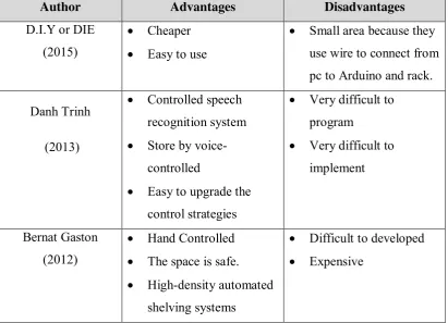
8 The benefit and drawbacks of every aforementioned rack storage that has been developed are as compared in table 2.1 below.
Table 2.1 Advantages and Disadvantages of rack storage that has been developed
Author Advantages Disadvantages
D.I.Y or DIE (2015)
Cheaper
Easy to use
Small area because they use wire to connect from pc to Arduino and rack. Danh Trinh
(2013)
Controlled speech recognition system
Store by voice-controlled
Easy to upgrade the control strategies
Very difficult to program
Very difficult to implement
Bernat Gaston (2012)
Hand Controlled
The space is safe.
High-density automated shelving systems
Difficult to developed
Expensive
2.4 Summary of Previous Project
9 controlled robotic component finder. This storage solves the locations problem with help of listening to voice instructions. This project is very difficult to develop and the cost to develop this project is expensive. Lastly, the automated shelving system come preferred with face panel control and can be configured with infrared remote access or LED touch pad controls. This project difficult to develop.
2.5 Software Overview
[image:24.595.181.518.340.492.2]2.5.1 Microsoft Visual Studio
Figure 2.1: Microsoft Visual Studio