1 INTRODUCTION
In the face of stiff competition, cost reduction and globalisation, marine industry today requires a quan-tum leap in the entire process of ship design, con-struction and operations to keep abreast and differen-tiate itself in the marketplace that is fast moving towards digital technologies. With the arrival of In-dustry 4.0 and artificial intelligence 2.0, digitalisation of ship design, construction and operation are gaining increasing attention in the marine industry as ships become eco-friendlier and smarter. However, the em-phasis of ‘smart’ design has been lacking in compar-ison to ‘smart’ manufacturing and a ‘smart’ ship. In particular, how can we further automate the ship de-sign process and integrate with smart manufacturing and smart ship considering the entire ship lifecycle? With industry 4.0, manufacturing is now moving to-wards more intelligent system or machineries that are highly connected. In the context of shipping, vessels are also becoming smarter with more automated sys-tems and begun to move towards unmanned or fully autonomous vessel, with the world’s first autonomous container feeder vessel YARA birkeland to be launched in 2018. Smart design is hereby proposed as an intelligent design process that is highly automated and collaborates closely with smart manufacturing and smart ships throughout the entire product lifecy-cle. By connecting up smart design with smart
manufacturing and smart ships, important infor-mation can be shared seamlessly across entire lifecy-cle of a ship and becomes a fully integrated through-life smart shipping network.
As marine industry moves towards eco-friendlier and energy-efficient ships, the design and optimisa-tion of hull forms continue to play an important role to help reduce fuel consumption and carbon dioxide emission. Traditional method of ship design and hull form optimisation requires many manhours by ship design firm and shipyards using the ‘trial-and-error’ approach, which is inefficient and does not guarantee optimum designs. While latest simulation based de-sign methods and tools help to automate some of these processes, they still require considerable human input and success at end result depends heavily on the designer’s experience and knowledge. Considering smart design, we introduce an innovative concept which aim to address the above issues by automating the hull form design process with minimum user in-terference and yet not compromising the quality of the results. This is achieved by combining evolution-ary algorithm with efficient shape variation approach known as morphing and hereby proposed as hybrid evolutionary algorithm and morphing (HEAM) ap-proach.
The focus of this paper is to introduce the concept of smart design as well as HEAM approach which possesses the potential to improve design efficiency
Smart Design of Hull Forms Through Hybrid Evolutionary Algorithm
and Morphing Approach
J.H. Ang & V.P. Jirafe
Sembcorp Marine Ltd, Singapore
C. Goh
University of Glasgow, United Kingdom
Y. Li
School of Computer Science and Network Technology, Dongguan University of Technology, China, and Faculty of Engineering, University of Strathclyde, United Kingdom
and produce more optimal hull forms. Section 2 de-scribes the concept of smart design which can link up smart manufacturing and smart ship operation pro-cess considering entire lifecycle. Section 3 proposes the HEAM approach which combines evolutionary algorithm with morphing to automate the hull form design and optimisation process. Section 4 provides the results of HEAM concept, followed by discussion and conclusion in section 5.
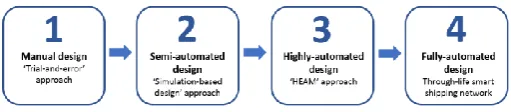
[image:2.595.308.558.337.541.2]2 SMART DESIGN OF SHIP AND HULL FORM Hull form design and optimisation is an important topic in the marine industry due to more stringent en-vironmental regulations and reduction of operation cost due to fuel consumption. An efficient hull form will help to reduce resistance acting on the vessel and thereby reducing fuel consumption and emission to the environment. As the marine industry moves to-ward digitalisation, it is essential to further automate the design process and connect up with other lifecycle processes to achieve fully automated smart design. An illustration of the various stages of hull form de-sign developments are provided in Figure 1 as below.
Figure 1. Development towards fully automated design process
From above figure, it started off with traditional method of hull form design which is based primary on ‘trial-and-error’ where ship designers create the in-itial hull form from scratch or modify from existing proven hull designs (stage 1). This manual method is extremely time consuming and only allows few de-sign variation and testing. Since the introduction of computer into ship design, simulation-based design (SBD) approach became dominant as it accelerates the design process by semi-automating the shape var-iation and optimisation process and validating the performance using computational fluid dynamics (stage 2). While SBD method helps to automate some of the design process, they still require considerable human input and the result often depends heavily on the designer’s experience and knowledge. This method is also isolated and does not usually consider external feedbacks such as manufacturing or ship op-eration. With the development of digitalisation and artificial intelligence, we can further automate the de-sign process so as to reduce the iterative process and free up the designer’s time for more critical task. This process is proposed under HEAM approach (stage 3) and will be covered in next section. Subsequently, the end goal is to fully automate the design process and connect up the entire product lifecycle process to also
include ship construction and operation. This can be achieved via through-life smart shipping network (stage 4) which will be further elaborated below. 2.1 Related works in simulation-based hull form
design
[image:2.595.32.288.369.425.2]Simulation-based designs (SBD) are used widely for performing numerical optimisation and evaluation of hydrodynamic performance of the hull form. Most simulation-based hull form design optimisation con-sists of three key processes- firstly, (1) the hull shape is linked to a design exploration function to search systematically for optimal design. Next, (2) the ge-ometry modification function will change the shape of the hull to create new designs. Following which, (3) the new shape generated will be evaluated on its performance function. This process will continue to iterate until the stopping criteria or most optimal hull design is achieved. An illustration of simulation based hull form design optimisation process is pro-vided in Figure 2.
Figure 2. Simulation-based hull form design optimisation pro-cess
Geometry modification plays an important role in ensuring the hull shape can be easily manipulated to form new shapes in order for the optimiser to investi-gate and evaluate. The key challenge here is to ensure every new shape generated must be smooth and of feasible design. There are 2 main approaches used to modify hull geometry- direct modification and sys-tematic variation. Direct modification changes the hull geometry by adjusting the hull coordinates man-ually using control points through curve or surface representations. While this method is highly flexible, it requires large number of control points to represent the shape and hence not very efficient for modifying the entire hull shape. Examples of direct modification includes Beizer curve, non-uniform rational basis spline (NURBS) and T-splines (Kostas et al. 2014). On the other hand, systematic variation modifies the hull shape using a function which considers global hull parameters (e.g. block coefficient, Cb) or series of local hull representation. This method is particu-larly useful for global modification which enables the entire hull form to be transformed more efficiently. However, shape changes are somehow more re-stricted and not very flexible as compared to direct modifications. Some recent examples of systematic variation methods applied in hull form optimisation include parametric modification (Saha & Sarker 2010, Brizzolara & Vernengo 2011) and free-form deformation (Campana et al. 2013).
Performance evaluation assess each candidate so-lution produced from the optimiser based on the ob-jective function. The most important performance pa-rameters that are influenced by shape of the hull include resistance and sea-keeping behavior and hence selected as key objective functions in most hull form design optimisation applications. For evaluation of resistance, Computational fluid dynamic (CFD) are used extensively in hull form optimisation which had been proven as an effective means to simulate the fluid flow around vessel. Examples of CFD methods used for resistance evaluation include potential flow (Nowacki 1996) and Reynolds Averaged Navier-Strokes Equation- RANSE (Tahara et al. 2006, Zha et al. 2014). For sea-keeping analysis, there are several numerical methods which include strip theory, uni-fied theory, green function method, etc. (Bertram 2000).
2.2 Related works in smart design, construction and operation
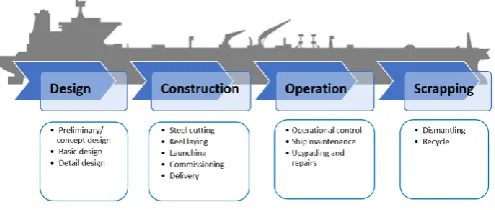
[image:3.595.313.561.41.146.2]With the development of digitisation and big data, it enables ships to become more connected and smarter. However, most ship lifecycle process now are rarely connected in reality. To illustrate this, we can look at the lifecycle and key milestone of a typical ship’s life-time as provided in Figure 3 below.
Figure 3. Typical ship life-cycle and key processes
From above figure, while the life-cycle processes are progressive and closely linked, information are not transferred interchangeably from one process to the other. As an example, once shipbuilder completes construction and ship owner takes over ownership of the vessel, they do not share operational information back to the shipbuilder which are useful for them to monitor the actual performance and use the infor-mation to improve on its subsequent designs. As such, it should be recognised that full digitalisation of ship life-cycle cannot be realised without elevating each process into more connected and automated process which considers the entire value chain.
Considering life-cycle for ships, we look at how these key processes can be elevated into smart design, construction and operation. Smart designs are rela-tively new concept and not explored widely in partic-ular ships or hull form design. It can be defined as an intelligent design process which is highly automated and ability to collaborates closely with smart manu-facturing and smart ship or operation throughout the entire lifecycle. Some early works on smart design by authors include (Ang et al. 2017a). Other smart de-sign application related to ship includes smart ship system design for electric ships (Chalfant et al. 2017).
Smart construction or manufacturing is currently a high interest topic that is being driven under the ad-vent of industry 4.0 (i4). I4, also known as forth in-dustrial revolution, aims to merge the real and physi-cal space through cyber-physiphysi-cal system. It provides a platform to transform traditional segregated manu-facturing process into fully connected manumanu-facturing system. Basic components and enabling technologies of i4 includes internet of things, collaborative robots, cybersecurity, cloud computing, additive manufactur-ing and big data analytics. I4 or smart factory concept are increasingly adopted and implemented in high tech manufacturing and aviation industry. There are currently very few applications of i4 in shipbuilding. One recent work done is a study of smart pipe system for shipyard (Paula et al. 2016).
reduce operation cost and improve safety and be-lieved to revolutionise ship design and operation. There are several works done recently on smart ship which includes one that considers the design of con-trol of power and propulsion system for smart ship (Geertsma et al. 2017) and another that consider smart ships in general (Jan 2017). Smart scrapping or de-commissioning of ships are not considered here due to its short duration comparing entire lifecycle but might be worth to look into in future works.
2.3 Through-life smart shipping network
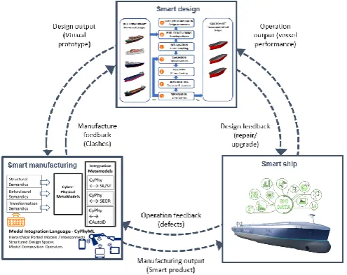
As mentioned in the beginning, the emphasis of smart design has been lacking in comparison to smart man-ufacturing and smart products. In particular, how is smart design going to integrate with smart manufac-turing and smart product when considering entire product lifecycle? One promising solution is a frame-work that connects and creates a feedback loop to link up smart manufacturing and smart product to smart design. By connecting up smart design with digital manufacturing and smart operations into a unified digital model, important information can be shared seamlessly across entire product lifecycle of a ship and becomes a fully integrated through-life smart shipping network, as introduced in (Ang et al. 2017a) and illustrated in Figure 4.
Figure 4. Through-life smart shipping network
By closing the loop between ship operation and de-sign through smart product, useful through-life data such as ship operating environment and actual perfor-mances can be collected, analysed and feedback into smart design process for producing more optimum fu-ture designs. In addition, smart design can be further enhanced by combining design automation process and digital product model under i4. By linking digital product model into the automated design process, we can provide an automated feedback loop from smart
product back to design to improve the design perfor-mance of future vessels.
3 HYBRID EVOLUTIONARY ALGORITHM AND MORPHING APPROACH
Considering the issue in current simulation based hull form optimisation with respect to the lack of efficient shape manipulation and robust optimisation tech-niques to automate the hull form design process and goal to elevate to smart design, a hybrid evolutionary algorithm and morphing (HEAM) approach was pro-posed by authors in (Ang et al. 2017b). The propro-posed methodology integrates evolutionary algorithm and curve morphing to automate the hull form design op-timisation and elevate into smart design.
3.1 Evolutionary algorithm
[image:4.595.38.286.429.625.2]Evolutionary algorithms (EA) are a group of generic population-based meta-heuristic optimisation tech-niques that are widely used in many different applica-tions due to its ability to solve complex problems and produce a set of globally optimal solutions. Among various EA methodologies, one of key methods used in hull form optimisation is genetic algorithm (GA). GA was first developed by (Holland 1975), which is a nature-inspired search heuristic method based on Darwinian Theory of natural selection and the ‘sur-vival-of-the-fittest’ principle. GA works on the prin-ciple of ‘genes’ and ‘chromosomes’ as illustrated in Figure 5.
Figure 5. Genetic algorithm working principle
[image:4.595.308.563.479.580.2]3.2 Curve morphing
Metamorphosis, also known as morphing, is a technique used widely in the animation industry to generate a sequence of images that smoothly trans-form a source to another target image. It is also ap-plied in computer graphic and industrial design to compute a continuous transformation from a source to another target shape. Morphing can be a very use-ful tool for the designer to modify, manipulate, trans-form the shape or geometry of the design in pursuit to improve the design attributes such as performance, quality, aesthetic, etc. Morphing can be catergorised into 2 main types- two-dimensional (2D) or three di-mensional (3D). 2D morphing consist of image morphing and curve morphing and 3D morphing in-clude surface morphing and volume morphing. In ship application, (Tahara et al., 2006) applied morph-ing usmorph-ing 3D patch model from NAPA to transform a ship hull model into another target model. (Kang & Lee 2010) applied 3D mesh-based surface morphing to generate intermediate hull models between two parent vessels.
Since the beginning of shipbuilding and subse-quent introduction of computer-aided design (CAD), 2D offset table remains the most fundamental repre-sentation of ship’s hull form. Hence until today, it is still used as the basis for designer to model and mod-ify the hull design. The advantage of using 2D hull lines from offset table are it is simple to represent the entire shape of the hull and easy to modify the hull form by adjusting the lines. In this paper, we apply curve morphing based on 2D hull lines to transform the shape of hull through interpolation and extrapola-tion between the hull lines of two or more hull forms.
Using morphing equation:
𝑀(𝑡) = (1 − 𝑡) × 𝑅0+ 𝑡 × 𝑅1 (1)
where M(t) is the morphed shape, t is the morphing parameter, R0denotes the source shape and R1 the
tar-get shape.
From above equation, we can see when t = 0, M(t) is also equal to 0 and hence the morphed shape is equivalent to source shape R0. Likewise, when t = 1,
M(t) = R1 which is the target shape. To illustrate the
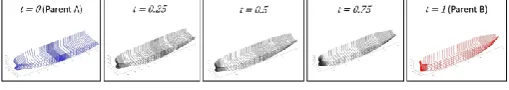
[image:5.595.309.560.29.177.2]concept, by using hull lines provided from the body plan of source and target vessels, we can morph and generate large number of intermediate shapes just by changing the morphing parameter (t). Other than in-terpolating between the source and target vessel, we can also extrapolate beyond the 2 hull lines to create new ‘extended’ lines. As an example, we take one hull line each from ship A (source) and ship B (target) at station 0.5 for both vessels. By applying curve morphing equation, we can generate interpolated and extrapolated curves as illustration in Figure 6.
Figure 6. Curve morphing through interpolation and extrapola-tion at staextrapola-tion 0.5
It can observe by applying only one morphing pa-rameter (t) constantly across all transverse stations, we can effectively morph or create the entire hull form between the source and target vessels. Key fea-ture of this curve morphing approach is the ability to capture complex shapes such as hull form using min-imal design variables, which in this case is repre-sented by morphing parameters (t).
3.3 Hybrid evolutionary algorithm and morphing approach (HEAM)
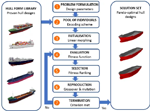
By combining the advantages of GA- ability to search for best global solution- and that of morphing- ability to generate smooth intermittent shapes from the com-bination of two or more hull form designs, we can now potentially create a wide range of hull form de-signs with improved efficiency and thereby finding the most optimal hull form. An overview of the pro-posed HEAM concept is provided in Figure 7.
Figure 7. Hybrid evolutionary algorithm and morphing approach
[image:5.595.308.560.495.681.2]3.3.1 Problem formulation
Before any optimisation process, it is important to first specify the design parameters which include ship type, principle dimensions as well as objective func-tions. Depending on the number of existing hull de-signs in hull form library, they can be catergorised by different ship types and selected to form the initial hull designs based on the design requirement. Princi-ple dimensions such as length between perpendicu-lars (Lpp), beam (B), draft (T) would need to be spec-ified as per design requirement. In this HEAM approach, we can scale up or down the existing ves-sels from hull form library to meet the design require-ment by applying linear transformation to modify the hull form according to desired length, beam and draft. Depending on vessel type, objective functions relat-ing to hull form optimisation may include reducrelat-ing resistance and seakeeping motion for vessels.
3.3.2 Pool of individuals
The next step of HEAM is to create the first pool of individuals and map them into unique encoding scheme. In ship design process, this can be obtained from existing hull forms from the hull form library or create from scratch. The advantage of using existing designs is the assurance of their performance which are validated to meet design objective and helps to shorten the design cycle, although the improvements are often incremental. Another alternative is to model a new hull form from scratch which will allow more freedom of design thereby allowing the creation for more innovative hull form designs. For the proposed HEAM approach, real-value chromosomes using morphing parameters (t) which captures the ship’s ge-ometry in X and Y planes according to their respec-tive frame or stations across Z planes, as illustrated in Figure 8. This provides a simple yet direct represen-tation of the ship geometry which allows the hull shape to be transformed easily by changing the morphing parameters (t) at various station locations along the entire vessel.
Figure 8. Encoding scheme using real value chromosome (t=0)
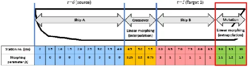
For initial population, first vessel model (parent A) will be assigned morphing parameter t=0 and second vessel model (parent B) will be assign t=1. More ves-sel models can be included using same arrangement to increase the variety of shapes and hence increasing the search space to achieve more optimal designs.
Under this HEAM approach, we introduce three applications of curve morphing by incorporating into above encoding scheme- i) constant morphing, ii)
[image:6.595.308.563.140.185.2]linear morphing and iii)varying morphing. Constant morphing is applied to morph the entire hull form us-ing same morphus-ing parameters within the encodus-ing scheme. For example, by applying the same morphing parameters (t) across the entire length of vessel, we can generate large number of intermittent designs as demonstrated in Figure 9.
Figure 9. Two parent vessels and intermediate vessels created by parallel morphing
Other than interpolating between 2 parent vessels, we can also extrapolate beyond the parent vessels us-ing morphus-ing method to create more ‘new’ designs. Linear morphing is used during crossover and muta-tion funcmuta-tion to smoothen the curve by applying grad-ual morphing parameters (t) between two parent mod-els. Varying morphing is used when we combine both constant and linear morphing or when multiple vessel types are combined together.
3.3.3 Initialisation
Prior to morphing operation, we need to prepare the hull coordinates for all the parent vessels so as to en-sure the hull form corresponds to each other. Consid-ering no two offset tables are identical in terms of number of coordinate points, we perform correspond-ence so as to create same number of points across all section curve for the parent vessels which are to be morphed. This can be done using cubic spline polation to create additional points at different inter-val of the section curve. Cubic spline interpolation is a piecewise continuous curve which passes through each of the values in a table of points, which is repre-sented in the following equation:
𝑆𝑖(𝑥) = 𝑎𝑖(𝑥 − 𝑥𝑖)3+ 𝑏𝑖(𝑥 − 𝑥𝑖)2+ 𝑐𝑖(𝑥 − 𝑥𝑖) + 𝑑𝑖 ;
for 𝑥 ∈ [𝑥𝑖, 𝑥𝑖+1] (2)
[image:6.595.34.287.581.643.2]where S(x) denotes the spline and [xi, yi] represents a
table of points for i=0,1,…,n for function y=f(x)
Figure 10. Curve correspondence using cubic spline interpola-tion
3.3.4 Fitness evaluation
In order to measure the ‘fitness’ of the parent ves-sels, we need to evaluate the performance of each hull form design based on the objective function. In most hull form optimisation, the objective function will be to reduce hull resistance and ship’s motion. For both objectives, the aim is to minimise the cost function as follow:
Min f (χ), χ ϵ X (3) Where f is the vector of design objectives, χ is vector of design variables and X is the feasible design varia-ble space.
At this stage, we will need to translate the 2D hull geometry into 3D surfaces by mapping the offset ta-ble into hull surfaces using surface generation method such as NURBS. The 3D surfaces will then be panel-ised and the resistance can be evaluated using numer-ical methods such as potential flow or Reynolds Av-eraged Navier-Strokes Equation (RANSE). For motion analysis, strip theory can be used which are available in most hydrodynamic analysis tools. Under this HEAM approach, we proposed the candidate de-sign solutions should be assessed using low-fidelity CFD method potential flow for resistance analysis. This is in view of the large number of candidate solu-tion to be evaluated and potential flow are preferred due to its efficiency and fairly good estimation during early ship design. High fidelity CFD method such as RANSE can be applied at later stage to validate the optimal design.
3.3.5 Selection
In GA, selection is a process of selecting which solu-tion will be used in reproducsolu-tion for generating new solutions. The principle is to always select the good solutions in order to increase the chance to obtain bet-ter individuals. For proposed HEAM approach, we apply roulette wheel selection which probalisatically
selects individuals based on their performance for next round of reproduction.
3.3.6 Reproduction- crossover and mutation
Crossover is an important operator in GA where chro-mosomes of two parents are combined to form new chromosome of the child. Principle of this operator is to create new individuals by mixing the good genes of their parents and subsequently lead to fitter indi-viduals. In this HEAM approach, we apply linear morphing to combine two or more existing hull form (parents) to generate new hull form designs (child) through interpolation to create smooth intermediate curves between the two parents, as illustrated in Fig-ure 11 below.
Figure 11. Crossover between ship A aft and ship B forward body through linear morphing (interpolation)
On top of morphing two different hull form to-gether in one hull concept, we can also join multiple hull forms (three or more) using varying morphing by simply applying linear morphing at intermittent sta-tions between different vessels. For combining ves-sels which are vastly different in term of sizes, rescal-ing through linear transformation can be applied to reduce or enlarge the hull form to match the other ves-sel.
[image:7.595.39.282.37.227.2]Mutation is the next reproduction process within GA where new genes are created in random to pro-duce a new genetic structure which helps to intropro-duce new elements into the population. In this HEAM ap-proach, we apply linear morphing at random station through extrapolation to create the chromosome of new solutions as illustrated in Figure 12 below.
Figure 12. Mutation at random stations through linear morphing (extrapolation)
While mutation is entirely random in nature, linear morphing can help to reduce the possibility of infea-sible designs such as unsmooth surface or odd shape generated during the optimisation process.
3.3.7 Termination criterion and solution set
[image:7.595.310.561.242.314.2] [image:7.595.308.562.584.655.2]the results identifying the pareto optimum design. In this HEAM approach, the termination condition can be based on total number of iterations or terminate if there no further improvement after 10 iterations. Ul-timately, the designer should decide the termination criterion based on number of initial designs available in hull form library and lead time for this initial de-sign process.
4 RESULTS AND DISCUSSIONS
To demonstrate the flexibility and benefits of curve morphing and proposed HEAM approach, we per-formed two case studies to- i) optimise the hull form of container vessel using two parent models through constant and linear morphing and ii) ‘split’ and com-bine three different vessel types using varying morph-ing.
4.1 Hull form optimisation of container vessel using HEAM approach
[image:8.595.306.563.113.180.2]In this first case study, we applied multi-objectives optimisation using HEAM approach to produce the hull form of a new container vessel using two existing vessels as initial designs. The design objective is to reduce total resistance and seakeeping motion of a container ship with principle dimension of 185m length between perpendicular (Lpp), 32m beam, 9m draft and design speed of 20 knots. The principle di-mensions for two parent container vessels are pro-vided as follow.
Table 1. Principle dimensions for two existing parent vessels.
______________________________________________ Principle Dimensions Container A Container B
______________________________________________ Lpp 185m 202.1m Beam (B) 32m 32.2m Draft (T) 9m 10.5m ______________________________________________ From the two parent vessels selected, we applied cor-respondence to match the number of coordinate points and performed linear morphing (interpolation and extrapolation) to form the initial population. Af-ter creating the initial designs, the designs are evalu-ated based on their total pressure resistance and max-imum heave response function. In this study, the performance of each candidate design is evaluated us-ing potential flow method and strip theory in NAPA program and it took less than five minutes to evaluate one hull form design using standard quad core work-station. Prior to reproduction, we performed rescaling using linear transformation of parent vessel B to meet the design criteria set in this case study. The crossover and mutation points were then selected randomly through the HEAM program written in Matlab. This randomness helps to generate more novel candidate designs which may not been considered by the
[image:8.595.34.263.504.569.2]designer if carried out manually. The preliminary re-sults of the hull form generated from HEAM program are provided as below.
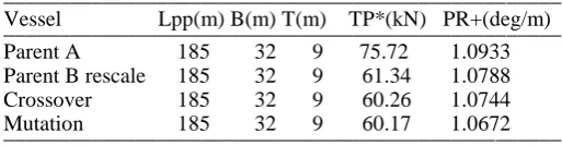
Table 2. Principle dimensions and results of candi-date solutions generated using HEAM program ___________________________________________________ Vessel Lpp(m) B(m) T(m) TP*(kN) PR+(deg/m) ___________________________________________________ Parent A 185 32 9 75.72 1.0933 Parent B rescale 185 32 9 61.34 1.0788 Crossover 185 32 9 60.26 1.0744 Mutation 185 32 9 60.17 1.0672 ___________________________________________________ * Total pressure resistance
+ Maximum pitch response function
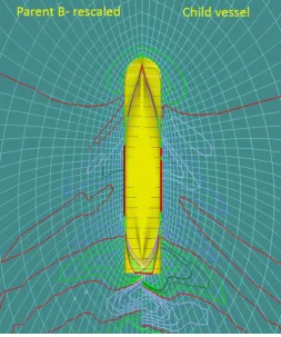
Figure 13. Wave profile comparing vessel parent B- rescaled and child vessel
4.2 Combination of three different vessel types using two-point crossover and varying morphing
In the next case study, we demonstrate here the pos-sibility of combining three different vessel types into one hull form through two-points crossover and var-ying morphing. This unique feature allows the segre-gation of hull form into three main sections- stern sec-tion, mid-section and bow secsec-tion, thereby enable the creation of more innovative hull form combination through mix-and-match process within the HEAM approach. Firstly, we select three different vessel types- a container vessel, one bulk carrier and an oil tanker. The principle dimensions for three vessels are provided as below
Table 3. Principle dimensions for three different types of sea-going vessels.
_________________________________________________ Aft body Mid-body Forward body _______ ________ ____________ Dimensions Container Bulk carrier Oil Tanker _________________________________________________ Lpp 202.1m 215m 314m
Beam (B) 32.2m 36m 58m Draft (T) 10.5m 15m 20.92m _________________________________________________ Next, we performed rescaling using linear transfor-mation to resize the vessels to the same principle di-mension, which is the same as oil tanker in this exam-ple. Following which, the three vessels are ‘split‘ into three separate sections and ‘join’ together using multi-target morphing. The combined vessels are il-lustrated as below in Figure 14.
[image:9.595.313.560.37.118.2]Figure 14a. Combination of three different vessel types using multi-target morphing
Figure 14b. Isometric view of 3 combined vessels
We can see from above example the versatility of two-points crossover and varying morphing method-ology which can combine three very different vessels in terms of function and size. This is very useful when applied in HEAM program which can potential create many more different types of hull form combinations and more innovative designs. It is recognised one key limitation of using existing vessel design within this HEAM approach is the new designs are closely linked to the parent and lack of freedom to create more in-novative designs. To overcome this limitation, de-signer can also select from existing vessels or create from scratch their own designs for HEAM to morph and generate new designs. For example, designer can choose between different design types of hull form in way of three main sections of the vessel- stern, mid and bow section as illustrated in Figure 15.
Figure 15. Possibility of mix-and-match of different designs us-ing two-points crossover and varyus-ing morphus-ing
[image:9.595.314.558.171.338.2] [image:9.595.312.557.612.729.2] [image:9.595.32.279.632.699.2]moprhing function will help to increase the solution space and thereby provides another function within HEAM or additional ‘tool’ for designers to create more innovative hull form.
4.3 Discussions
As compared to existing hull form design process, there are several benefits of this HEAM approach. Firstly, it starts from a pool of existing proven hull forms designs as compared to improvement from only one ‘sister-ship’ hull designs, which enables the ex-ploration of wider solution spaces and generating more optimal hull forms. Second, by performing morphing via interpolation and extrapolation between these proven designs, it enables automated geometry modification without any designer input. It should be noted the concept of HEAM approach is not to re-place the role of designer but instead to supplement and provide as an additional tool for designer to ex-amine a wide variety of existing hull form and narrow down to few optimal designs very quickly before working on the design further. Thirdly, by incorporat-ing morphincorporat-ing parameter into encodincorporat-ing scheme within HEAM, we can effectively transform the entire hull shape with as little as one design variable- morphing parameter, t, thereby increasing the overall efficiency of geometry modification and optimisation process. Finally, HEAM allows ‘mix-and-match’ of hull forms through unique crossover and mutation functions which enables the creation of more innovative hull form. As demonstrated in the results section, this ap-proach has the flexibility to combine 3 very different vessels whereby increasing the solution space for more optimal hull. It should be noted HEAM ap-proach is not limited to only ship hull form. It can also be extended to other related design applications such as aerospace and automobile main body design.
In order to realise the full benefits of HEAM and to be applied to ship design process, there are still sev-eral issues that needs to be addressed and overcome. Firstly, it is widely known within the industry auto-mating the hull form design process is already very challenging in its own sense. In fact, there are no known procedure or tools that are able to automati-cally translate hull coordinates to surface and mesh-ing for evaluation. In this study, we are only able per-form the translation from morphed points to surfaces manually using NAPA modeling software and feed the results back to HEAM program. Secondly, one can observe from second case study that the principle dimensions of the three vessels were adjusted drasti-cally as the result of re-scaling in order for all the ves-sels to join together. Hence, this may not represent the actual hull form characteristic as compared to the original vessel. Thirdly, the full benefits of GA are best exploited in applications with huge data set or solution space. In our example, we are limited to only few hull forms due to manual surface modeling and
CFD evaluation. Finally, while crossover function within GA helps to create new designs by combining the genes of two parent vessels, it is recognised the combination of two good genes might leads to crea-tion of a bad gene with poorer performance. Never-theless, more studies will be carried out on the above issues and we hope to address them in our subsequent publication.
5 CONCLUSION
In this paper, we presented two concepts- through-life smart shipping network and smart design through HEAM approach. These two concepts provide the di-rection towards digitalised and smart shipping where design, construction and operation of ships can be-come more integrated and efficient. Through-life smart shipping network combine the key lifecycle processes into an integrated network where useful in-formation can be exchanged at different phases in an collaborative manner. HEAM approach combines morphing and GA to generate series of new hull de-signs in a more automated manner and perform ‘in-telligent’ search to narrow down to more optimal de-signs. By incorporating curve morphing concept into unique encoding scheme, we utilise GA operators such as crossover and mutation function to transform the hull shape through constant morphing, linear morphing and varying morphing. Two case studies are applied to optimise the hull form of container ves-sel through HEAM approach consisting constant and linear morphing and also combined three different parts of vessel into one single hull using varying morphing. Through computational intelligence and connected lifecycle network, it is envisioned this smart HEAM approach will help to improve the over-all efficiency and ability to produce more efficient and smarter ships in the near future.
REFERENCES
Ang, J.H., Goh, C., Saldivar, A.F. & Li, Y. 2017a. Energy-effi-cient through-life smart design, manufacturing and operation of ships in an industry 4.0 environment. Energies 10, 610. Ang, J.H., Goh, C., Jirafe, V.P. & Li, Y. 2017b. Efficient hull
form design optimisation using hybrid evolutionary algo-rithm and morphing approach; Conference on Computer Ap-plications and Information Technology in the Maritime In-dustries, 3-4 October 2017, Singapore.
Berrini, E., Mourrain, B., Duvigneau, R., Sacher, M. & Roux, Y. 2017. Geometric model for automated multi-objective op-timization of foils. VII. International Conference on Compu-tational Methods in Marine Engineering, May 2017, Nantes, France.
Bertram, V. 2000. Practical Ship Hydrodynamics. Butterworth-Heinemann.
Chen, X., Diez, M., Kandasamy, M., Zhang, Z.G., Campana, E.F. & Stern, F. 2014. High-fidelity global optimization of shape design by dimensionality reduction, metamodels and deterministic particle swarm, Engineering Optimization. Campana, E.F., Serani, A. & Diez, M. 2013. Ship optimization
by globally convergent modification of PSO using surrogate based newton method, Engineering Computations.
Chalfant, J., Langland, B., Rigterink, D., Sarles, C., McCauley, P., Woodward, D., Brown, A. & Ames, R. 2017. Smart Ship System Design (S3D) Integration with the Leading Edge Ar-chitecture for Prototyping Systems (LEAPS), Electric Ship Technologies Symposium, IEEE.
Feng, B.W., Hu, C.P, Liu, Z.Y, Zhan, C.S & Chang, H.C. 2011. Ship resistance performance optimization design based on CAD_CFD, International Conference on Advanced Com-puter Control, 18-19 January 2011. Harbin, China.
Geertsma, R.D., Negenborn, R.R., Visser, K., Hopman, J.J. 2017, Design and control of hybrid power and propulsion systems for smart ships: A review of developments, Applied Energy 194: 30–54.
Holland, J.H. 1975, Adaptation in Natural and Artificial Sys-tems, Univ. of Michigan Press.
Jan, O.R. 2017, Towards Shipping 4.0, International Confer-ence on Smart Ship Technology, 24-25 January 2017, Lon-don, UK.
Jacquin, E.; Derbanne, Q., Bellevre, D., CORDIER, S., Ales-lessandrini, B., Roux, Y. 2004. Hull form optimisation using free surface RANSE solver, 25th Symp. Naval Hydrodynam-ics, St.John’s.
Kang, J.Y. & Lee, B.S. 2010, Mesh-based morphing method for rapid hull form generation, Computer-Aided Design. Kim, H. 2012, Multi-Objective Optimization for Ship Hull Form
Design, George Mason University.
Kostas, K.V., Ginnis, A.I., Politis, C.G. & Kaklis, P.D. 2014, Ship-Hull Shape Optimization with a T-spline based BEM-Isogeometric Solver, Comput. Methods Appl. Mech. Eng. Nowcki, H. 1996, Hydrodynamic design of ship hull shapes by
methods of computational fluid dynamics, Progress in Ind. Math. at ECMI : 232-251.
Paula, F., Diego, N., Tiago M.F., Manuel, A.D. and Miguel, V. 2016, Smart pipe system for a shipyard 4.0. Sensors, 16, 2186.
Park, J.H., Choi, J.E. & Chun, H.H. 2015, Hull-form optimiza-tion of KSUEZMAX to enhance resistance performance, Int. J. Nav. Archit. Ocean Eng.
Saha, G.K., Sarker, A.K. 2010, Optimisation of ship hull param-eter of inland vessel, Int. Conf. Marine Technology, Dhaka. Tahara, Y.; Tohyama, S. & Katsui, T. 2006, CFD based multi-objective optimization method for ship design, Int. J. Numer-ical Methods in Fluids 52: p.28
Tahara, Y., Peri, D., Campana, E.F., Stern, F. 2011, Single and multiobjective design optimization of fast multihull ship, J. Mar. Sci. Techn.
Zha, R.S., Ye, H.X., Shen, Z.R. & Wan, D.C. 2014, Numerical study of viscous wave making resistance of ship navigation in still water, J. Marine Sci. Appl. 13: 158-166