AN IN - VITRO ANALYSIS OF THE DIMENSIONAL
ACCURACY OF DIES OBTAINED BY USING
DIFFERENT IMPRESSION TRAYS
Dissertation submitted to
THE TAMIL NADU DR. M.G.R. MEDICAL UNIVERSITY
In partial fulfillment for the degree of
MASTER OF DENTAL SURGERY
BRANCH VI – PROSTHODONTICS
CERTIFICATE
This is to certify that this dissertation titled “AN IN - VITRO ANALYSIS OF THE DIMENSIONAL ACCURACY OF DIES OBTAINED BY USING DIFFERENT IMPRESSION TRAYS” is a
bonafide record of work done by Dr. SREE VIDYA LAGISETTY,
postgraduate student of M.D.S branch VI Prosthodontics of Ragas Dental
College and Hospital, under our guidance and supervision during her post graduate study period between 2003 – 2006.
This dissertation is submitted to The Tamilnadu Dr. M.G.R. Medical
University in partial fulfillment for the award of the degree of Master of
Dental Surgery in Branch VI – Prosthodontics.
Dr. N.S.AZHAGARASAN,M.D.S. Dr. S. RAMACHANDRAN,M.D.S.
Guide, Principal,
Professor and Head, Ragas Dental College and Hospital,
Department of Prosthodontics, Chennai. Ragas Dental College and Hospital,
Chennai.
DATE : 14.09.2005
ACKNOWLEDGEMENT
This dissertation is the result of work,
whereby I have been accompanied and supported by
many people. It is a pleasure that I have now
the opportunity to express my gratitude for all
of them. This column is not enough to express my
gratitude, to all the people who have helped me
during this course and yet I humbly would like
to do so.
I owe a great deal to my respected and
beloved Professor
Dr. N.S. Azhagarasan M.D.S., Professor, Head of
the Department of Prosthodontics , RAGAS Dental
College and Hospital, Chennai, for being my
source of strength throughout my postgraduate
curriculum. I would like to express my
wholehearted thanks for his unconditional trust,
enormous patience and concern to help me to
complete my dissertation.
It is a pleasure to be able to record my
personal debt to my former Professor and H.O.D,
Prosthodontics, Dr. M. Vasanth Kumar M.D.S, for
his constant help, guidance, support and
I would like to express my esteemed
thankfulness to the Principal,
Dr. S. Ramachandran, M.D.S, RAGAS Dental College
and Hospital, Chennai, for his help and
encouragement throughout my post graduate
course. I also thank him for permitting me to
utilize the facilities in the institution..
I wish to express my sincere thanks to
Professor A.Kanagaraj, M.A., M.Phil., Secretary,
RAGAS Educational Society, Chennai for
permitting me to make use of the amenities in
the college.
I would like to express my sincere
gratitude to my respected Professor Dr. K.
Chitra Shankar M.D.S., Professor, Department of
Prosthodontics, RAGAS Dental College and
Hospital, Chennai, for her valuable guidance,
continuous encouragement, timely suggestions and
support which helped me throughout my post
graduate curriculum.
I express my heartful thanks to Dr. Jaya
Krishna Kumar M.D.S, Dr.Manoj Rajan M.D.S,
and Dr. Sanketh Reddy M.D.S for their whole
hearted co-operation and for their moral support
I would like to express my thanks to Dr. S.
Ganesh, Professor, Department of Physics, Anna
University and Dr. P. Aruna, Assistant
Professor, Department of Physics, Anna
University for letting me to use their expertise
and equipment needed for the study.
I would also like to thank Ms. Hema,
Statistician, RAGAS Dental College and
Hospital, for her valuble guidance in
statistically analyzing the data for this study.
I am indebted. to my family especially for
their faith in me and their emotional support
rendered to me during my post graduate course.
Last but not the least, I would like to
thank all my friends and colleagues for their
help and encouragement throughout my
TABLE OF CONTENTS
PAGE NO.
1. Introduction ... 1
2. Review of Literature ... 4
3. Materials and Methods ... 25
4. Results ... 39
5. Discussion ... 51
6. Conclusion ... 66
7. Summary ... 67
ANNEXURE A
LIST OF TABLES
Table No.
1. Code designation for impression trays used in the study
2. Code designation for impression materials used in the study
3. Measurement of dimensions of individual molar (47)
4. Measurement of dimensionsof individual premolar (45)
5. Measurement of inter-abutment distance between prepared pre molar (45) and molar(47)
6. Basic data obtained by measuring the distance for eleven different coordinates in standard typhodont model (Group S1-S10)
7. Basic data obtained by measuring the distance for eleven different coordinates from the specimens of Group IIA (Samples M1-M10)
8. Basic data obtained by measuring the distance for eleven different coordinates from the specimens of Group IIB (Samples P1-P10)
9. Basic data obtained by measuring the distance for
eleven different coordinates from the specimens of Group IIC (Samples C1-C10)
10. Basic data obtained by measuring the distance for
11. Comparison of mean values of coordinates measured from samples of different groups (Group I, Group IIA,Group IIB,Group IIC & Group IID).
12. A Mean and Standard deviation of different
groups at Coordinate 1 (18-22)
B ANOVA test for Coordinate 1 (18-22)
13. A Mean and Standard deviation of different
groups at Coordinate 2 (20-24)
B ANOVA test for Coordinate 2 (20-24)
14. A Mean and Standard deviation of different
groups at Coordinate 3 (15-17)
B ANOVA test for Coordinate 3 (15-17)
15. A Mean and Standard deviation of different
groups at Coordinate 4 (14-15)
B ANOVA test for Coordinate 4 (14-15)
16. A Mean and Standard deviation of different
groups at Coordinate 5 (15-12)
B ANOVA test for Coordinate 5 (15-12)
17. A Mean and Standard deviation of different groups at Coordinate 6 (10-7)
B ANOVA test for Coordinate 6 (10-7)
18. A Mean and Standard deviation of different
groups at Coordinate 7 (4-3)
B ANOVA test for Coordinate 7 (4-3)
19. A Mean and Standard deviation of different
groups at Coordinate 8 (4-2)
20. A Mean and Standard deviation of different groups at Coordinate 9 (4-1)
B ANOVA test for Coordinate 9 (4-1)
21. A Mean and Standard deviation of different
groups at Coordinate 10 (15-3)
B ANOVA test for Coordinate 10 (15-3)
22. A Mean and Standard deviation of different
groups at Coordinate 11 (22-10)
LIST OF FIGURES
Figure No.
1. Impression Trays
2. Impression Materials
2A Monophase Addition Silicone
2B Putty And Light Body Addition
Silicone
3. Die Stone (Ultra Rock Type Iv)
4. Articulated Typhodont
5. Articulated Typhodont After Teeth Preparation
of 45, 47
6. Occlusal View of Prepared Teeth 45 & 47 Showing
the Prepared Notches
7. Numerical Position and Designation of the Notches
Prepared on the Typhodont Premolar (45) and
Molar (47)
8. 8A & 8B Impression Made with Stock Metal
Perforated tray - Two-Step Putty Wash Impression technique
9. 9A&9B Impression Made with Stock Plastic
Perforated tray - Two-Step Putty Wash Impression Technique
10. Impression Made with Custom Tray - Monophase
11. Impression Made with Triple Tray – One step Putty Wash
Impression Technique
12. Vacuum Mixer
13. Vibrator
14. Dies Obtained from Different Impression Trays
15. Travelling Microscope
GRAPHS
16. Dimensional variation comparision at Coordinate 1 with
different impression trays
17. Dimensional variation comparision at Coordinate 2 with
different impression trays
18. Dimensional variation comparision at Coordinate 3 with
different impression trays
19. Dimensional variation comparision at Coordinate 4 with
different impression trays
20. Dimensional variation comparision at Coordinate 5 with
different impression trays
21. Dimensional variation comparision at Coordinate 6 with
different impression trays
22. Dimensional variation comparision at Coordinate 7 with
different impression trays
23. Dimensional variation comparision at Coordinate 8 with
24. Dimensional variation comparision at Coordinate 9 with
different impression trays
25. Dimensional variation comparision at Coordinate 10 with
different impression trays
26. Dimensional variation comparision at Coordinate 11 with
INTRODUCTION
The traditional goal of successful prosthodontic restorations
depends upon the accuracy of reproduction of casts and dies. A cast or die
is a positive replica made from a negative replica which is traditionally
named as impression. There are various techniques, concepts and theories
advocated by research methodologists to obtain an accurate impression.
Accordingly, the impression trays have been designed to suit the
requirements of the restoration to be prepared and the consistencies of the
tissues in the area where the impression has to be made.
These impression materials vary in consistencies from rigid to
elastic after they set. However, for obtaining accurate details and to
maintain dimensional stability the impression material should possess
adequate flow and highly elastic properties. The property of flow enables
the material to obtain all details and elastic properties enable their use in
undercut areas. Hence, elastic impression materials are “the” choice for
making the impression of dentulous dental arches.
The device which holds the impression material to make
impressions is known as impression tray. There are various dentulous
impression trays available for making impressions such as complete stock
trays made up of either metal or plastic. These trays are also available as
There are viewers who felt that complete impression trays are
preferred over partial trays for fabricating accurate cast restorations. Some
advocates feel that the rigidity and close adaptability of the impression
trays may limit the thickness and permit the correct flow of the material to
the required areas, for obtaining surface details and to maintain
dimensional stability. Recent advances focused on gnathological concepts
stress that the impression should be made when the teeth are at the
maximum intercuspation. It is also suggested that the impression should
be well adherent to the impression trays. To achieve this the
manufacturers have designed perforated impression trays. Adhesives are
also supplied for bonding of impression material to the trays. Some trays
have mesh work with either natural or synthetic materials incorporated to
improve retention of the impression material to the tray.
To prevent cross-infection, use of disposable or plastic trays has
been advocated. Also, impression materials which do not show any
exothermic reaction or warmth, either at the time of manipulation or
during setting resulted in the introduction of tray designs with polymeric
materials. The material and design framework of the impression tray are
also to be considered, as elastomers are available in different consistencies
to make impressions. Tray design may form a factor for the accuracy and
for the dimensional stability of the impressions to produce accurate casts
Hence viewing all the above facts, the impression tray designs are
being modified from time to time to suit the particular material, its
consistency and the technique followed. Irrespective of the above criteria,
the ultimate aim is to produce a precise cast or die which is an analogue of
the prepared dental structure.
Keeping the above views in mind the study has been undertaken
with the following objectives:
1. To measure and compare the dimensions of the stone dies
obtained from polyvinyl siloxane impression using different
types of impression trays.
2. To evaluate variations of dimensions of stone dies obtained
from polyvinyl siloxane impression made from one type of
impression tray to the other.
3. To evaluate least dimensional variation of stone dies made
REVIEW OF LITERATURE
In the construction of fixed prostheses, the impression stage plays a
vital role in preparing a precise analogue of the natural tissues.
Impression making for Fixed Prosthodontics has matured from
carving wooden or ivory blocks that accommodated the intraoral contours
to the more scientific methods that are used in the modern day practice.
Rush Bailey (1955)59 explained the advantages of rubber base impression materials as being very elastic and dimensionally stable. More
than one cast can be made successfully from the same impression if care is
exercised. Exceptionally smooth and accurate dies could be obtained. He
recommended that impressions pouring could be delayed.
Fairhurst CW et al (1956)21 explained that for most rubber base impression materials, the elastic properties improved considerably when
they were allowed to set longer than recommended by the manufacturer.
He also stressed that large deviations from the manufacturer's
recommended ratio of the components is not advisable since inferior elastic
properties will result. He recommended use of an individual tray allowing
2 to 3 mm thickness of the impression material, avoiding extension of the
material into larger adjacent undercuts.
temperature and at 37 0 C. The effect of variations in proportioning of base
and the catalyst were determined and a comparative evaluation of the
consistencies of the products conducted. They recommended suitable
manipulation techniques to get optimum working time. They concluded
that outstanding inlays could be prepared by using the rubber base products
for impression making.
William H Gilmore et al (1959)71 investigated seven popular silicone impression materials to determine various factors which influence
their accuracy. Their study involved the use of master castings on hydrocal
dies poured in impressions treated in varying ways. They concluded that,
the use of a double mix procedure, will produce more accurate impressions
than a single mix technique. A uniformly thin (2mm or less) layer of
silicone produces more accurate results than thicker or unevenly distributed
masses of material. Accuracy could be improved by allowing the
impression material to become slightly elastic before seating.
Myers and Stockman (1960)50 discussed the factors that affect the accuracy and dimensional stability of the poly sulfide impression materials.
The mixing time of the material is critical and the recommended time
should be used. Under mixing resulted in inaccurate casts. Also they
recommended use of a custom tray as compared to a stock tray. The
number of accurate casts from a second pour in the same impression was
Frederic Custer et al (1964)22 investigated the accuracy and dimensional stability of a silicone rubber base impression material. When a
silicone impression material was used, greater accuracy was obtained in
custom trays or with wash techniques than with impressions made with
stock trays. Second casts made in the same impression were only one half
as accurate as the first casts.
Carl P Regli and Ellsworth K Kelly (1967)9 stressed the importance of the closed mouth impression technique. They described that
mandibular flexure occurs in mouth opening. They were of the opinion
that this amount of mandibular distortion is sufficient to affect the fit of the
partial denture. The phenomenon of decreased mandibular arch width in
opening movements creates enough stress on abutment teeth with a fixed
partial denture to bring about its early failure.
James A Stackhouse (1970)35 investigated the accuracy of stone dies as affected by the three dimensional changes in rubber impression
during setting and following removal from the mouth. He used Thiokol and
silicone rubber impression material in custom tray for the study. Uniform
dies were produced from silicone than from mercaptan rubber. The use of
custom tray produced undersized dies.
Joseph V Mitchell and Joseph A Damele (1970)40 conducted a study to investigate the effects of the restrictive influence of the impression
reversible and irreversible hydrocolloids and two elastomeric materials
(polysulfides and silicone base). They utilized perforated, rim lock and
undercut brass trays of equal volume. Their findings indicated that tray
form had a significant bearing upon the amount of impression distortion
displayed. Shrinkage of the impression material toward the attachment of
the tray was a major contributor to distortion.
James A Stackhouse (1971)36 gave different advantages of the custom tray he fabricated. The exothermic reaction of the polymerizing
resin enhances rapid drying of the adhesive which bonds the elastomer to
the tray. Minimal impression material is needed. It ensures an even and
optimal thickness of impression material with minimum danger of over
compression. The tray is rigid, has little dimensional change, and maintains
the elastomer in good contact with the preparation.
Wilson (1971)73 studied statistical principles in experiential design of the trays, showed that the impression trays with addition silicone
produced casts indisguinshable from standard dimensions than that of
polyether and polysulphide.
Fusayama et al (1974)22 developed a new technique called the laminate single impression technique. The author conducted a study to
check the accuracy of the stone dies made by four techniques namely the
single mix impression technique using the regular type material, the double
wash type and the laminated single impression technique. He concluded
that double impression technique without spacing produced the greatest
distortion. Laminated single impression technique produced the least
distortion.
Thomas J De Marco (1974)68 described that the shape of the mandible is designed so that it can withstand any bending or shearing
stress and also prevent any dimensional changes or fracture during
function. Depressor muscles insert into the mandible that change the shape
of the mandible during depression. He conducted a study to determine
bending movement at various degrees of opening. No change in the width
of the mandible occurs upto 28% of opening of the mouth and thereafter
the change in the width is related to the percentage of opening which is due
to the stresses exerted by muscles that depress the mandible.
Clinically this study indicated that full mouth impression techniques
would best be conducted at a closed position as possible since wider the
patient opens the mouth, the greater the mandibular distortion.
Reisbick and Matyas (1975)56 conducted an invitro study to evaluate the accuracy of the casts made from impressions that utilized new
silicone system type I and type II elastomers. The measurements were
made initially on the die and template to provide a reference standard and
Ten impressions were made with each elastomer system. These
silicone systems proved to be as accurate as other standard impression
materials and could also be used for dental duplication procedures.
Stackhouse (1975)64 investigated various brands of elastic impression materials. He concluded that all but two of the silicone and
mercaptan elastomers studied conformed to ADA Specification No. 19 for
mixing time, working time, and consistency. When the die material was
poured in 30 minutes, there were no significant differences in accuracy
among all of the elastomers tested.
Davis et al (1976)17conducted a study to determine the most retentive surface preparation for the self curing acrylic resin tray and to
compare the bond strengths of selected commercial polysulfide, silicone
and polyether impression materials to acrylic resin tray material. Results
showed that the surface yielded by the acrylic resin formed against tinfoil
provided better retention for the rubber base than any other surface tested.
The use of wax or asbestos spacers would not degrade the resin surface if
tin foil or aluminum foil were used as a separating medium.
Stanffer JP (1976)65 investigated the general accuracy of four groups of elastic impression materials for a complete-arch fixed prosthesis.
He tested the accuracy of hydrocolloids, silicones, polysulphide rubbers
and polyether by visual comparison and indirect measurement methods. He
and silicone impression; whereas hydrocolloids and polysulphide rubbers
gave less satisfactory results.
Eames WB (1979)19 conducted a study to examine the accuracy and dimensional stability of 34 elastomeric impression materials of 13
manufacturers. The amount of contraction exhibited by all materials at 30
minutes after making impression ranged from 0.11% to 0.45%. At 24 hrs,
stability ranged from 0.15% to 0.84%. Addition reaction silicones
exhibited least change.
Eames et al (1979)18 studied the effect of the bulk of the material on the accuracy of the impression and die. Omnivac trays were constructed
using 2 mm plastic to provide 2, 4 and 6 mm spaces for the impression
materials. The impressions were measured and the results showed that 2
mm spacing gave overall better accuracy than either the 4 or 6 mm tray
spaces.
James N Ciesco et al (1981)37 conducted a research to compare the dimensional stability and accuracy of selected elastomeric impression
materials at various time intervals and also to determine the effect of using
a custom tray with these materials. They evaluated: two polysulphides, two
silicones and one polyether. These materials were subjected to simulated
clinical conditions. Polyether material consistency yielded superior results
followed by addition reaction silicone, lead-cure polysulphide and
Lacy AM et al (1981)45conducted a study to compare the accuracy and dimensional stability of polysulfides, poly ether and poly vinyl
siloxanes by comparing the rate and magnitude of change of die size
obtained from sequential pours of dental die stone in a given impression
over a four day period. The modes of impression involved putty-wash
systems and wash - adhesive custom tray systems. They concluded that
addition silicones are the most stable of elastomers currently available and
best results could be achieved by use of custom trays and adhesives.
Roland P Pagniano et al (1982)58 conducted a study to ascertain the linear dimensional change of four commercial cold curing acrylic resin
custom tray materials and to measure the dimensional changes of the
acrylic resin materials. The results showed that most rapid linear shrinkage
of all materials occurred in the first hour after mixing and that the greater
the period of time a cold curing acrylic resin custom tray is stored prior to
use, the more stable it becomes. Ideally, waiting at least 9 hours after
fabrication of a custom tray allows the materials tested to become
comparatively stable.
Edmund G Wilson et al (1983)20 described double arch impression technique in which double arch impression trays were used. While
describing the technique he felt that double arch impression trays can be
used with any type of elastomeric impression material. He was also of the
opinion that double arch impression technique requires fewer steps,
transmission from one patient to another. Further the centric relation record
is also made at time of making the impression. Physical deformation of the
mandible during opening is eliminated and natural shifting of the teeth to
assume a maximum intercuspation can be registered. The counter
impressions are poured first.
Peter T Williams et al (1984)53 conducted an invitro study to compare the dimensional stability of six polysiloxane materialswith one
condensation silicone, three polysulfides and one polyether. Results
showed that all the addition silicone materials had exceptionally good
dimensional stability and when poured immediately their dimensional
change was negligible.
Sandric (1984)60 reviewed various impression materials for precision negative mold and stated that “irreversible hydrocolloid is not
sufficiently accurate for cast restoration.” He further mentioned that
polyether and poly vinyl siloxanes are preferable because they exhibit
sufficient long term dimensional stability.
Valderhaug J et al (1984)69 described rubber base impression materials as highly accurate and stable when they have an even thickness
of 2-4 mm achieved within an acrylic custom tray. He compared the
stability of impressions made in custom trays and chromium plated brass
tray with polyether and silicone. He concluded that the dimensional
materials and also due to bonding adhesives on non perforated trays with
limited elastic properties. Linear dimensional stability of the impression
made in stock trays was not inferior to the stability of impressions made in
custom trays.
Glen H Johnson et al (1985)27 conducted a study to describe accuracy of addition silicone, condensation silicone, polysulphide and
polyether to evaluate accuracy as a function of time and pouring and
repeated pour of die material independently. The silicones demonstrated
best recovery from undercuts and least change in dimensions between
initial and second pour of an impression.
Goldfogel M et al (1985)30 examined newer improved auto polymerizing acrylic resin tray materials. Twelve auto polymerizing acrylic
resin tray materials were studied for linear curing shrinkage with a
measuring microscope. All trays exhibited shrinkage during the 24 hour
test period. He concluded that auto polymerizing acrylic resin tray
materials should not be used for an impression the same day they are made,
unless the tray is boiled.
Alfred W Fehling et al (1986)1 conducted a study to establish an optional interval between making an auto polymerizing acrylic resin
custom tray and using it. Linear dimensional changes occurred through out
6 hours, which suggested that any impression made in a methyl metha
conveniently possible. He concluded that while an aged tray is preferred, it
is acceptable to make an impression in an auto polymerizing resin custom
impression tray after 40 minutes.
Glen H Johnson et al (1986)28 describes addition silicones to be more accurate and dimensionally stable. He described the effect of tray
design on dimensional accuracy of the impressions. Addition silicone
material used along with putty wash technique produced more accurate
dies than condensation silicone. He stated that the custom tray is
impression tray of choice even for addition silicones which produced
relatively little polymerization shrinkage and are dimensionally stable.
Bomberg TJ et al (1988)7 conducted a study to determine the effect of the some of the adhesion factors of various combinations of trays and
adhesive usage. These included the lack of the usage of liquid adhesive
cement bonding in perforated and non perforated custom acrylic resin and
stock impression trays. Perforated, non perforated custom acrylic resin
trays and perforated, non perforated stock trays were used along with two
impression techniques (Single mix impression technique and putty-wash
system). The results showed that use of full application of adhesive and the
perforated trays were associated with the minimization of marginal
opening. The use of stock or custom trays and use of the putty wash or
Chang chi Lin et al (1988)11conducted an experimental design to compare the accuracy of complete arch impressions of six different
impression materials using complete crown preparations. A maxillary
partially edentulous model was modified as the master model and four
orientation marks were made to standardize the measuring position of each
stone cast in front of the travelling microscope.
The results showed that polyethers produced the most accurate
complete arch replicas followed by vinyl polysiloxanes, followed by the
poly sulfides and the irreversible – reversible hydrocolloids.
Reitz CD and Clark NP (1988)57 found that the disadvantage of addition silicone impression material is the setting inhibition caused by
some brands of latex gloves. He is of opinion that if putty system is used,
gloves that do not interfere with setting reaction should be selected.
Gary A Schoenrock(1989)31 described laminar impression technique as a precise rapid and predictable alternative to traditional
method of impression making in fixed prosthodontics. This technique used
double arch plastic trays where he advocated making of putty impressions
before the preparation of tooth and later making the wash impression after
the preparation of tooth. Precise injection of wash material avoided
wastage and the flushing action of injecting ensures a continuous flow of
material and aids in removal of sulcular contaminants to produce a clear
Naofumi Shigeto et al (1989)52 evaluated the dimensional accuracy of dies in complete dental arch casts made by three different methods of
dislodging the impression tray. The dimensional changes of the molar die
were significantly affected by the dislodging method in the inclined way
but not of those of the incisor die. The anteriorly inclined method showed
fewer dimensional changes than the posteriorly inclined method. On the
other hand, the dimensional changes of the incisor die were not significant
by any dislodging method. If the impression tray is removed by the
inclined way, the fulcrum should be chosen at a region remote from the
abutment instead of at the proximal region.
Prattern and Craig (1989)54 conducted a study to compare the wettability of hydrophilic addition silicone to that of other elastomeric
impression materials.The impression materials were evaluated for their
ability to produce gypsum casts without air bubbles and voids.The results
showed that hydrophilic addition silicone impression material has been
found to have wettability not significantly different from that of a
polyether impression material.
Setz J (1989)61 mentioned that addition silicone was introduced as a dental impression material in 1970. This material was also known as
polyvinyl siloxane (PVS). It has much greater dimensional stability and its
Barry Marshak et al (1990)4 explained a technique to achieve an accurate seating of putty impression tray by use of unprepared teeth and
provisional restorations in the arch as landmarks, stops and guiding planes.
The putty impression was made with resin provisional restorations in place
on the prepared teeth and allowed to set. The provisional restorations
provided space for wash material. They recommended that to ensure
accurate reseating of the putty impression and venting away excess wash
material, all undercuts, projections into the embrasures or tooth material
were to be cut away from the putty before loading of the wash material.
Claudio P Fernandes et al (1990)13 reviewed several silicone impression materials and found that accurate replication of intraoral
structures was due to their favorable physical properties. In several studies,
addition reaction silicones have been found to be the most stable
impression material, followed by polyethers, polysulfides, and, last by
condensation reaction silicones. However disadvantage of addition
polymerization silicones is their poor wettability properties. Plasma
treatment has been reported to improve the wettability of silicone
impression materials.
Their study investigated plasma treatment of silicone impressions
and found that the detail reproduction was superior in casts produced from
Glenn E Gordon, Johnson and David Drennon (1990)26 evaluated the accuracy of reproduction of stone casts made from impressions using
acrylic resin, a thermoplastic and plastic trays and addition silicone,
polyether and a polysulphide impression materials. Impressions of the
fixed partial denture simulation were made with all three impression
materials and all the three tray types. Impressions with cross arch and
anteroposterior land marks were made with all three types using addition
silicone impression material. Results indicated that custom made trays of
acrylic resin and the thermoplastic material performed similarly regarding
die accuracy and produced clinically acceptable casts. The stock plastic
tray consistently produced casts with greater dimensional change than the
two custom trays.
Ray A Walters and Steven Spurrier (1990)55conducted a study on the effect of tray design and tray modification on linear dimensional
changes in impression made with polysulphide material. According to
them custom tray provides less bulk and reduces the distortion. Tray
design, the use and the placement of adhesive or the perforations present in
the tray and also the bulk of the impression material in the tray have
definite effects on the accuracy of the resulting impression of the abutment
teeth prepared. They suggested a modified custom tray with 3 mm spacer
and adhesive for optimal results.
condensation silicone, and polyvinylsiloxane putty adhesive systems.
Results showed no significant difference in adhesive bond strength to auto
polymerizing resin between the former four impression materials studied.
The polyvinylsiloxane putty did not adhere to its impression adhesive.
Wassell and Ibbetson (1991)70 did an invitro investigation to assess the influence of stock trays on the accuracy of impressions recorded with
heavy light body and putty light body wash impression techniques. Two
brands of trays were tested and the same trays were reinforced with acrylic
resin. Significant inaccuracy at the second molar area was found for all
trays when putty- light body impressions were made. Heavy light body
impressions regardless of the type of the tray produced highly accurate dies
at the critical site. Resultant overall cast distortion was reduced.
Chee WWL and Donovan TE (1992)12 reviewed the composition, physical properties and manipulative variables of polyvinyl siloxane and
also discussed guidelines for techniques that will result in optimum
performance. Several methods of using very high viscosity (putty)
materials to form “trays” to obtain uniform bulk of the wash impressions
were described and the disadvantages of each of these techniques were
pointed out. They recommended that for best results resin custom trays
should be used routinely.
of condensation silicone impression materials. However he has suggested
putty wash impression technique for addition silicone impression materials
for obtaining better results of dimensional stability of the impression
because of stable polymerization reaction of addition silicone.
They evaluated the accuracy of one-step putty wash impression with
two-step putty wash impression techniques using five different addition
silicone materials. They concluded that the accuracy of addition silicone
impression material is affected more by material than technique. Accuracy
of putty-wash one step impression technique was not different from the
putty wash two-step impression technique.
Idris B et al (1995)34 conducted a study to compare the accuracy of the putty/wash one step and two-step technique with an addition-type
silicone impression material and evaluated the effect of undercuts of two
different configurations on the accuracy of an addition-type silicone by the
use of these techniques. The results indicated that the inter abutment
distances increased slightly compared with the stainless steel model for
both techniques, but the differences between techniques were not
considered to be clinically important.
Justin I Boulton et al (1996)42 investigated horizontal and vertical accuracy of gypsum dies produced from addition silicone, polyether and
polysulphide impressions using both custom and stock trays. They found
materials other than polysulphide produce stone dies with minimal
dimensional changes. Stock trays produced significant decrease in
abutment height with polysulphide when compared with putty wash
impression technique. Custom trays produced decreased vertical dimension
with polysulphide when compared too the putty wash impression
technique.
Joseph Nissan et al (2000)41 conducted a study to assess the accuracy of 3 putty-wash impression techniques using the same impression
material (polyvinyl siloxane) in a laboratory model.
The 3 putty-wash impression techniques used were (1) 1-step (putty
and wash impression materials used simultaneously); (2) 2-step with 2 mm
relief (putty first as a preliminary impression to create 2 mm wash space
with prefabricated copings. In the second step, the wash stage was carried
out); and (3) 2-step technique with a polyethylene spacer (plastic spacer
used with the putty impression first and then the wash stage).They
concluded that the polyvinyl siloxane 2-step, 2 mm, relief putty-wash
impression technique was the most accurate for fabricating stone dies.
Luca Ortensi (2000)46 explained the fabrication method of a modified custom tray using auto polymerizing acrylic resin. The tray was
fabricated by intraoral relining with auto polymerizing resin that is
polymerized extra orally. The final impression was obtained during the
areas were refined by trimming excess resin with burs of a known diameter
to create a 2 mm clearance for the elastomer. According to Luca Ortensi,
this procedure was time saving as it reduces the need for a retraction cord
and minimizes inaccuracies that would necessitate another impression.
Andrew Lane et al (2003)2 conducted a study to establish whether a double arch impression technique could produce restorations comparable
with those produced by use of the complete arch technique and to
investigate reported time and material savings. Two sets of impressions,
one complete arch in a stock metal tray and one double arch in a plastic
double arch tray were made in addition polymerized silicones. Equal
numbers of crowns were made from complete and double arch
impressions. At the time of crown placement, the accuracy of fit, occlusal
harmony and time taken for try in, weight of impression material were also
recorded. Results showed that double arch impressions were found to take
less time, use less material and preferred by patients and resulting
restorations were no less accurate than those made from complete arch
impressions.
Cynthia S Petrie et al (2003)15 investigated by comparing dimensional accuracy and surface detail reproduction of 2 hydrophilic VPS
impression materials when used under dry, moist and wet conditions.
Dimensional accuracy was measured by comparing the average length of
the middle horizontal line in each impression to the same line on the metal
showed that conditions (i.e.) dry, moist and wet did not cause significant
adverse effects on the dimensional accuracy of either material. Best surface
detail results were obtained only under dry conditions for both the
materials.
Jeffery A Ceyhan et al (2003)38 described the use of metal and plastic dual arch trays. He compared the accuracy of gypsum working dies
made from the impressions with metal and plastic dual arch trays and
complete arch custom tray. He found no significant differences in die
accuracy among three trays for mesiodistal and occlusogingival
dimensions. Plastic dual arch trays produced more accurate working dies in
the buccolingual dimension than the metal dual arch tray. Custom tray was
not shown to differ from dual arch trays in accuracy.
Monica J Cayouette et al (2003)49 described dual arch impression tray techniques as an alternative method for making the impressions for
fixed prosthodontics. They measured and compared the three dimensional
differences in gypsum casts poured from impressions using plastic full arch
stock tray, triple tray-metal reinforced rigid dual arch tray and a triad
custom tray, with vinyl poly siloxane and polyether materials to the
dimensions of original master model. A three dimensional system was used
to determine coordinates of 32 points on the master model and resulting
casts. Intra and inter tooth dimensions were calculated from the measuring
coordinates. They found that casts made using a custom tray with both
polyether showed no detectable inaccuracies and were reproducible as the
master model. The custom tray technique was more accurate than other
impression techniques. Changing in the sequence of pouring of the casts in
the dual arch impression tray produced statistically no difference. The
accuracy of the dual arch impression technique does not depend upon the
reduction of the teeth and the thickness of the two impression materials
which were used for the study.
George Cho et al (2004)25 evaluated the rigidity and ability to resist deformation of disposable plastic stock trays and metal stock tray when
used in conjunction with a high viscosity polyvinylsiloxane impression
material. The dimensions of the tray in cross section at the mandibular
right first molar area were measured before, during and after the
impression procedure with electronic digital calipers.
The results indicated that the disposable plastic trays were not
sufficiently rigid to resist deformation when used with very high viscosity
putty material. There was distortion of the trays both across the arch and in
MATERIALS AND METHOD
The objectives of the study were to apply the usage of different types of trays for evaluating the dimensions of the dies fabricated from selected impression techniques using the polyvinyl siloxane impression
material.
IMPRESSION TRAYS
The following four types of impression trays were used to carry out
this study (Fig 1).
Stock metal tray (Fig 1-M)
A stock metal tray of complete dentulous perforated type made up
of stainless steel was selected as one of the trays for loading the
impression material and making the impressions. The tray is manufactured
by Sun German Dental Company. Size L4 was selected.
Stock plastic tray (Fig 1-P)
A complete dentulous perforated plastic stock tray made from
Dentaurum Dental Company of suitable size, L4, was selected. The tray is
not as rigid as metal stock tray.
Custom tray (Fig 1-C)
Fabrication of custom tray
A sheet of base plate wax with thickness of 2mm is softened, folded
and placed on the mandibular member of the typhodont dentulous teeth
attached to the frame of the mandibular arch fitted to the rubber mold
simulating the mandibular dental arch. The softened wax was adapted to
the cast and the excess wax extending more than 2-3 mm beyond the neck
of the teeth was trimmed. The wax thus adapted was formed as a spacer
for the impression material and also for covering the undercut areas in the
given teeth.
3x3 mm windows were punched in the wax to provide for occlusal
stop. The stop space was created distal to the required tooth for tooth
preparation which was utilized for evaluating tooth dimensions.
An aluminum foil was adapted over the spacer wax. The aluminum
foil prevents the wax from impregnating the surface of the tray during the
exothermic polymerization of acrylic resin and also presence of wax layer
on the inner surface will diminish bonding of the tray adhesive applied
before placement of the impression.
Auto polymerizing resin was mixed according to manufacturer’s
instructions. When it reached a dough-like stage, it was molded into a
shape of the mandibular arch and then adapted onto the spacer and
aluminum foil formed over the typhodont dental arch framework. The
was mixed and a handle was attached to the tray. After the completion of
polymerization, the tray was removed smoothened and polished. Bur holes
were made to perforate the tray after removal of the spacer. The finished
tray was used to make the impressions. The tray was standardized to
provide for uniform thickness of impression material.
Triple tray (Fig 1-T)
It is also called dual arch impression tray. It has a plastic framework with a U shaped frame and a piece of fabric mesh. The mesh
connects the sides of the tray in the superior –inferior dimensions. This
mesh is fixed with in the triple tray. Posterior and anterior design trays are
available. The posterior design tray was used for the study.
TABLE 1
CODE DESIGNATION FOR IMPRESSION TRAYS USED IN THE STUDY
NAME OF THE TRAY MATERIAL COMPANY CODE
Stock metal tray Stainless steel Sun Germany M
Stock Plastic tray Plastic Dentaurum P
Custom tray Autopolymerising Resin Custom made C
Triple tray Plastic frame
with a fabric mesh
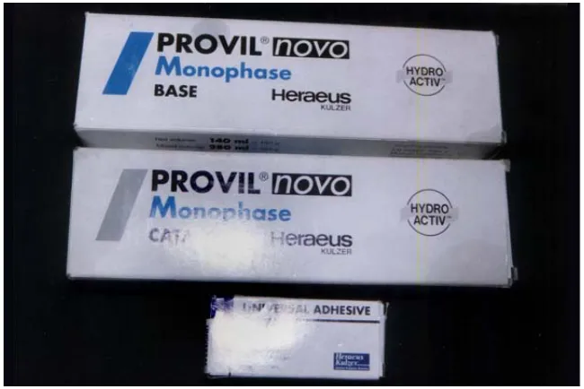
IMPRESSION MATERIAL (Fig 2A &2B)
The impression was of dentulous type. Hence addition silicone
(polyvinylsiloxane) elastomeric impression material was used in the study.
Three different viscosities such as, putty, light-body and monophase were
used.
TABLE 2
CODE DESIGNATION FOR IMPRESSION MATERIALS USED IN THE STUDY
TYPE CONSISTENCY COMPANY CODE
Addition silicone Putty Flexitime (Heraeus
Kulzer)
P
Addition silicone Light – body Flexitime (Heraeus Kulzer)
L
Addition silicone Monophase Provil novo (Heraeus Kulzer)
M
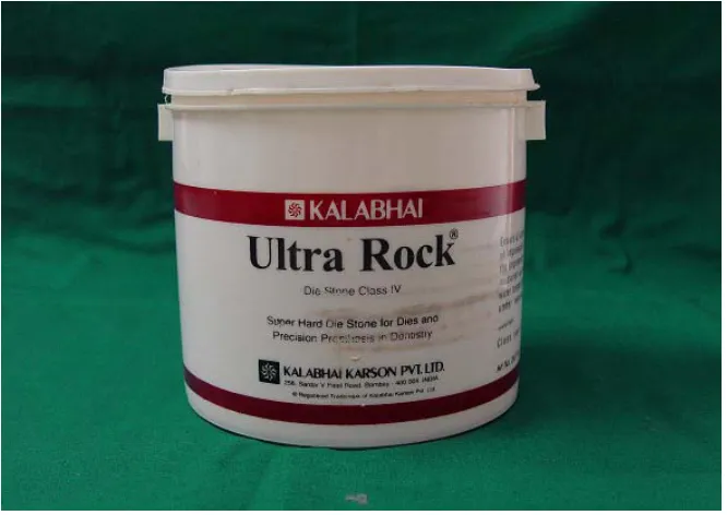
DIE STONE (Fig 3)
Type IV, Die stone (Ultra Rock, Kalabhai Karson pvt Ltd) was
selected to pour the impressions. The specifications according to
manufacturer’s instructions are as follows:
Color- Beige.
Mixing time-30 seconds (mechanical).
Setting time-approximately 6 minutes.
Hardening time-approximately 30 minutes.
Setting expansion-0.08%.
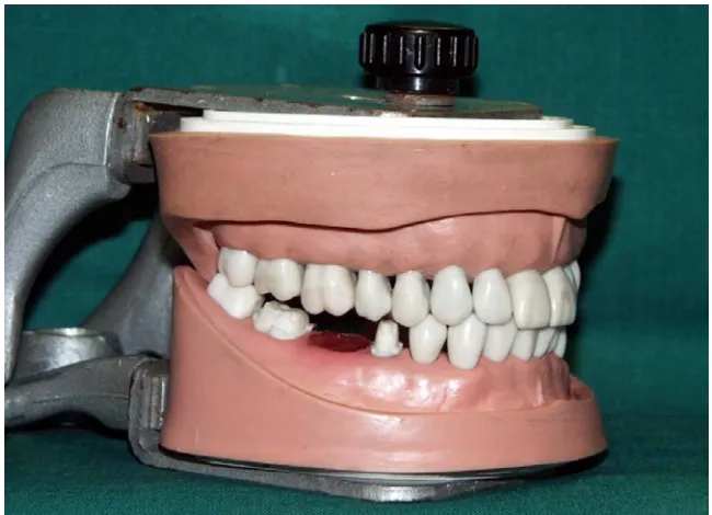
TYPHODONT ARTICULATOR WITH TEETH SET (Fig 4)
Typhodont teeth attached to the hinge articulator (Kavo) have been
used for the study. Tooth number 46 was removed to create a pontic space
to simulate a 3–unit Fixed Partial Denture situation, in which teeth number
45 and 47 were considered as abutments (Fig 5).
PREPARATION OF TYPHODONT TEETH FOR GROUP I SAMPLES (Standard Group/Control Group) (Fig 5)
Among the entire dental arch, two teeth were selected for the study.
The typhodont teeth, 45 – right mandibular second premolar and 47 - right
mandibular second molar, were prepared for full veneer crowns by
following the principles of tooth preparation.
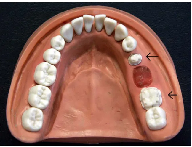
Preparation of Notches (Fig 6 &7)
In addition, on the premolar (45), index notches were placed at the
junction of the occlusolabial surfaces on either side of the preparation of
the labial surface, one facing towards mesial and the other one facing
towards distal. In the same way, index notches were placed on the lingual
surface of point angles at the junction of occlusolingual surfaces, one
facing towards mesial and one facing towards distal.
Regarding the molar tooth, six index notches were made as follows
at mesiobuccoocclusal, distobuccoocclusal point angles, occlusolabial line
distolinguoocclusal point angles and occlusolingual line angle, at the
center of the tooth. These indexes were made for measuring the
dimensions of the dies for the study.
In the same way, on the premolar a total number of seven index
notches were made on the cervical finish line step facing the occlusal area.
These notches were placed, two on the labial side, three on the lingual side
and one each on the proximal side.
Similarly, on the molar a total number of eight index notches were
made on the cervical finish line step facing the occlusal area. These
notches were placed, three on the labial side, three on the lingual side and
one each on the proximal side. Numbers were assigned to all the notches
to aid in the measurement.
Thus all precautions were followed not only for tooth preparation,
but also for the accurate measurement of the dies. The prepared teeth with
notches which were attached to the rubber mold of the dental arch along
with the unprepared teeth were considered for the control group study.
The dimensions between specific notches were represented as coordinates
and were measured on the prepared teeth itself (Tables 3, 4, &5). Ten
readings were taken for each coordinate. Each reading was designated
PREPARATION OF STUDY GROUP (GROUP II) SAMPLES
In order to obtain dies for the study group, impression procedures
were carried out using addition silicone impression material (Fig 2A & 2B) with the study group of trays( Fig 1).
Specimens for Group II A and B
(IIA – Dies made from metal stock tray with two-step putty wash
impression technique)
(IIB- Dies made from plastic stock tray with two-step putty wash
impression technique)
To prepare Group IIA and IIB specimens, metal and plastic stock
trays coded as ‘M’ and ‘P’ were selected (Figs 1-M & 1-P). The tray
selection was based on the close adaptation of the trays to the prepared
typhodont teeth. The tray was checked for its extension and spacing for
the material and tried on the typhodont. The two-step putty wash
impression technique was followed for both metal and plastic trays.
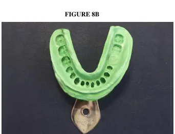
Impression technique (Two –step putty wash impression technique) (Figs 8A, 8B, 9A & 9B)
Adhesive was applied on the inside of the tray. High viscosity putty
was mixed according to the manufacturer’s instructions. Equal amount of
base and catalyst were taken and kneaded. As it is common with all
addition silicone impression materials, inhibiting reactions of the material
done with bare hands. A total mixing time was 45 seconds and working
time of 2min 30 seconds as instructed by the manufacturer was employed.
The putty was rolled into an elongated cylinder and inserted into the stock
tray. Putty was covered with spacer (polyethylene sheet) provided by the
manufacturer. The tray was placed on the model in a rocking motion. The
tray was held in the same position till the material was set. (2minutes 30
seconds). The tray was removed, spacer was peeled off and the excess
material removed with sharp knife.
The light-body material was syringed starting from one proximal
side to the other all over the prepared teeth with an automixing gun. The
light-body impression material was injected on the putty impression in the
tray which was made earlier. The tray was repositioned over the arch
(seating from posterior to anterior). Final set was awaited for 2min30
seconds and then the impression was removed.
Ten impressions with metal stock tray (Group IIA) and ten
impressions with the plastic stock tray (Group IIB) were made by this
technique.
Evaluation of set impression:
• Elastomeric material was present 0.5mm beyond visible
finish line.
• No tray show through in any of the areas of impression.
• No voids present.
Specimens for Group II C
(IIC – Dies made from custom tray with monophase addition
silicone).
To prepare Group IIC specimens, custom tray coded as ‘C’
(Fig 1-C) was selected. Impression was made from monophase addition silicone impression material using custom tray. The procedure of making
custom tray for this study group has already been mentioned.
Impression technique ( Fig 10)
Adhesive was applied to the inner surface of the custom tray and
the borders of the tray. The monophase material was mixed according to
manufacturer’s instructions. Equal amount of base paste and catalyst paste
was mixed on a glass slab with a mixing time of 30 sec.
The same material was loaded in the tray and syringed over the
preparation. (Total working time-2.5 minutes). The tray was placed on the
arch and final set of the material awaited (4.5minutes) and the impressions
were removed.
A total of ten impressions of the arch were made using this
Specimens for Group II D
(IID- Dies made from triple tray using one-step putty wash
impression technique)
To prepare Group II D specimens, triple tray coded as ‘T’ (Fig 1-T) was selected. Impressions were made with addition silicone using putty
and light body viscosities. Single stage impression technique was used.
Precautions were taken to check the impression tray so that the framework
did not interfere with the teeth in the articulated typhodont.
Impression technique (Fig 11)
High viscosity putty was mixed according to manufacturer’s
instructions. Equal amount of base and catalyst were taken and kneaded.
The putty was rolled and placed on either side of the triple tray and low
viscosity material is dispensed onto putty using a dispensing gun and
some amount on the prepared teeth to avoid any air entrapment.
First the tray was placed on the mandibular member and the
maxillary member of the master model was closed until both arches were
touching and a 2.5lb weight was placed on the top of the maxillary
member simulating the biting force49. The tray was held in same position
till the material was set (2min 30 sec).
Impressions were removed from the master model by first breaking
maxillary arch of the master model was lifted while holding the tray in
place against the mandibular arch. Finally, the tray was separated from the
mandibular arch by grasping the handle only. Impressions were stored at
room temperature.
A total of 10 impressions were made using this technique.
Thus a total of 40 impressions were made using four different
impression trays used for the study.
FABRICATION OF STONE DIES FOR ALL SPECIMENS OF GROUPII A, B, C AND D
The die stone (Ultra Rock Class IV) was supplied in bulk packaging
from the manufacturer. The impressions were poured in die stone 15
minutes after the impressions were made as per the manufacturer’s
instructions. At the time each impression was poured, 100gm of powder
was weighed using a balance, and 20 ml of room temperature distilled
water was measured and placed in a vacuum mixing bowl to which
powder was added and mixed by hand until the powder was wet. The
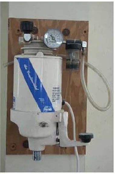
mixture was then mechanically spatulated (Fig 12) under vacuum for 60 sec according to manufacturer’s directions. Then the stone was poured in
all impressions. At the time of pouring, the impressions were placed on the
The dual arch impressions were poured on the preparation side first.
The dental stone was allowed to set for 40 min and then the opposing side
was poured. The casts were separated after 40- 45 min after both sides
were poured. Care was taken to see that the stone was dry at the time of
separating the casts from the impressions.
Once the casts were separated, they were trimmed on a model
trimmer to remove excess stone on either side. The models were trimmed
so that one tooth is left on either side of the prepared teeth.
Base was poured for the prepared dies using dental stone in a base
former. Care was taken to keep the preparation parallel to the base. Then
the dies were stored at room temperature.
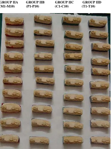
Thus a total of forty samples were fabricated from the impressions
made using four types of impression trays (Fig 14).
The samples obtained from the metal tray were designated as
Group IIA: M1 to M10 =10 samples.
The samples obtained from the plastic tray were designated as
Group IIB: P1 to P10 =10 samples.
The samples obtained from custom tray were designated as
Group IIC: C1 to C10 =10 samples.
The samples of obtained from triple tray were designated as
MEASUREMENT OF GROUP I (CONTROL GROUP) & GROUP II (STUDY GROUP)
Eleven coordinates were formulated for the measurement of
dimensions (calculated between the grooves present) of individual
premolar, molar typhodont teeth and the inter-abutment distance between
them and also of individual dies of premolar, molar and the interabutment
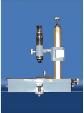
distance between them. The measurements were done with travelling
microscope. (Fig 15) and the data obtained were tabulated for calculating the results.
TABLE 3
MEASUREMENT OF DIMENSIONS OF INDIVIDUAL MOLAR (47)
COORDINATE DIMENSION (Measured between index notches as under)
1 18-22
2 20-24
3 15-17
4 14-15
TABLE 4
MEASUREMENT OF DIMENSIONSOF INDIVIDUAL PREMOLAR (45)
COORDINATE
DIMENSION
(Measured between notches points as under)
6 10-7
7 4-3
8 4-2
9 4-1
TABLE 5
MEASUREMENT OF INTER-ABUTMENT DISTANCE BETWEEN PREPARED PRE MOLAR (45) AND MOLAR (47)
COORDINATE
DIMENSION (Measured between notches points as under)
10 15-3
11 22-10
FIGURE 1
IMPRESSION TRAYS
FIGURE 2A
MONOPHASE ADDITION SILICONE IMPRESSION MATERIAL
[image:51.612.153.478.447.664.2]FIGURE 2B
PUTTY AND LIGHT BODY ADDITION SILICONE IMPRESSION MATERIAL
FIGURE 3
[image:52.612.150.483.470.706.2]FIGURE 4
ARTICULATED TYPHODONT
FIGURE 5
[image:53.612.153.478.464.699.2]FIGURE 6
FIGURE 7
NUMERICAL POSITION AND DESIGNATION OF THE NOTCHES PREPARED ON THE TYPHODONT PREMOLAR (45) AND MOLAR (47)
LEGEND ON NEXT PAGE
48 47 46
LEGEND LEGEND FOR PREMOLAR (45) FOR MOLAR(47)
NUMBER
ASSIGNED POSITION OF THE NOTCH 1 MESIO BUCCO OCCLUSAL POINT
ANGLE
2 DISTO BUCCO OCCLUSAL POINT ANGLE
3 MESIO LINGUO OCCLUSAL POINT ANGLE
4 DISTO LINGUO OCCLUSAL POINT ANGLE
5 MESIO BUCCO CERVICAL POINT ANGLE
6 DISTO BUCCO CERVICAL POINT ANGLE
7 DISTO CERVICAL LINE ANGLE 8 MESIO LINGUO CERVICAL POINT
ANGLE
9 DISTO LINGUO CERVICAL POINT ANGLE
10 MESIO CERVICAL LINE ANGLE 11 LINGUO CERVICAL LINE ANGLE
NUMBER
ASSIGNED POSITION OF THE NOTCH 12 MESIO BUCCO OCCLUSAL POINT
ANGLE
13 MESIO OCCLUSAL LINE ANGLE 14 DISTO BUCCO OCCLUSAL POINT
ANGLE
15 DISTO LINGUO OCCLUSAL POINT ANGLE
16 LINGUO OCCLUSAL LINE ANGLE 17 MESIO LINGUO OCCLUSAL POINT
ANGLE
18 MESIO CERVICAL LINE ANGLE 19 MESIO BUCCO CERVICAL POINT
ANGLE
20 BUCCO CERVICAL LINE ANGLE 21 DISTO BUCCO CERVICAL POINT
ANGLE
22 DISTO CERVICAL LINE ANGLE 23 DISTO LINGUO CERVICAL POINT
ANGLE
24 LINGUO CERVICAL LINE ANGLE 25 MESIO LINGUO CERVICAL POINT
FIGURE 8A & 8B
[image:57.612.154.496.418.681.2]IMPRESSION MADE WITH STOCK METAL PERFORATED TRAY - TWO-STEP PUTTY WASH IMPRESSION TECHNIQUE
FIGURE 8A
FIGURE 9A&9B
IMPRESSION MADE WITH STOCK PLASTIC PERFORATED TRAY -TWO-STEP PUTTY WASH IMPRESSION TECHNIQUE
FIGURE 9A
FIGURE 10
IMPRESSION MADE WITH CUSTOM TRAY- MONOPHASE SINGLE MIX IMPRESSION TECHNIQUE
FIGURE 11
FIGURE 12
VACUUM MIXER
FIGURE 13
[image:60.612.222.412.145.433.2] [image:60.612.155.476.499.716.2]FIGURE 14
DIES OBTAINED FROM DIFFERENT IMPRESSION TRAYS
[image:61.612.123.511.186.708.2]FIGURE 15
[image:62.612.171.459.251.641.2]RESULTS
The following results were drawn from the study which compared
the dimensional accuracy of the dies generated from four different
impression trays.
Ten samples were made in each group and in each sample eleven
measurements were made for eleven coordinates. Each coordinate
represents a dimension measured between two specific grooves made on
the prepared typhodont teeth and dies. Hence 110 readings were taken for
each of the five groups, in which one group (Group I) was the prepared
teeth mounted on a typhodont which was taken as a Standard and the
other four groups (Group IIA, IIB, IIC and IID) were the samples prepared
from the impressions made by using different impression trays. 10
readings were taken for each of the eleven coordinates for the standard
group (Group I).
Table 6 shows the basic data obtained by measuring the distance for
eleven different coordinates in standard typhodont model (Group
I-S1-S10). Ten readings were taken for each coordinate. The last column shows
the average of 10 readings at a particular coordinate. The readings are
shown in millimeters obtained on viewing the samples under the travelling
Table 7 shows the basic data obtained by measuring the distance for
eleven different coordinates from the specimens of Group IIA (samples
obtained from impressions of metal stock tray, M1-M10). In each of the
ten samples, eleven measurements were made for eleven coordinates. The
last column shows the average of 10 readings at a particular coordinate.
The readings are shown in millimeters obtained on viewing the samples
under the travelling microscope. The values are recorded at the same
coordinates as for Group I.
Table 8 shows the basic data obtained by measuring the distance for
eleven different coordinates from the specimens of Group IIB (samples
obtained from impressions of plastic stock tray, P1-P10). In each of the ten
samples, eleven measurements were made for eleven coordinates. The last
column shows the average of 10 readings at a particular coordinate. The
readings are shown in millimeters obtained on viewing the samples under
the travelling microscope. The values are recorded at the same coordinates
as for Group I.
Table 9 shows the basic data obtained by measuring the distance for
eleven different coordinates from the specimens of Group IIC (samples
obtained from impressions of custom tray, C1-C10). In each of the ten
samples, eleven measurements were made for eleven coordinates. The last
column shows the average of 10 readings at a particular coordinate. The
the travelling microscope. The values are recorded at the same coordinates
as for Group I.
Table 10 shows the basic data obtained by measuring the distance
for eleven different coordinates from the specimens of Group IID (samples
obtained from impressions of triple tray, T1-T10). In each of the ten
samples, eleven measurements were made for eleven coordinates. The last
column shows the average of 10 readings at a particular coordinate. The
readings are shown in millimeters obtained on viewing the samples under
the travelling microscope. The values are recorded at the same coordinates
as for Group I.
Table 11 shows the comparison of mean values of coordinates
measured from samples of different groups (Group I, Group IIA, Group
IIB, Group IIC and Group IID).
Table 12A shows the mean and standard deviation of Group I,
Group IIA, Group IIB, Group IIC, and Group IID at coordinate 1(18-22).
The dimensions were measured between index notches 18 and 22 (18-22).
The standard deviation was calculated keeping N=10 in each group. Table
12A also shows 95% confidence interval for mean gap. Lower boundary
shows the minimum mean gap in all the groups and the upper boundary
shows the maximum mean gap in all groups at coordinate 1.