UNIVERSITI TEKNIKAL MALAYSIA MELAKA
SIGNIFICANT EFFECT OF DIFFERENT BASE METAL IN
METAL SHEET SPOT WELDING
This report is submitted in accordance with requirement of the Universiti Teknikal Malaysia Melaka (UTeM) for the Bachelor of Mechanical Engineering Technology
(Automotive Technology) with Honours
by
MOHAMAD RAFIEZI BIN MAT ZAINU ZAMAN B071310326
910811-03-5921
UNIVERSITI TEKNIKAL MALAYSIA MELAKA
BORANG PENGESAHAN STATUS LAPORAN PROJEK SARJANA MUDA
TAJUK: Significant Effect of Different Base Metal in Metal Sheet Spot Welding.
SESI PENGAJIAN: 2016/17 Semester 1
Saya MOHAMAD RAFIEZI BIN MAT ZAINU ZAMAN
Mengaku membenarkan Laporan PSM ini disimpan di Perpustakaan Universiti Teknikal Malaysia Melaka (UTeM) dengan syarat-syarat kegunaan seperti berikut:
1. Laporan PSM adalah hak milik Universiti Teknikal Malaysia Melaka dan penulis. 2. Perpustakaan Universiti Teknikal Malaysia Melaka dibenarkan membuat salinan
untuk tujuan pengajian sahaja dengan izin penulis.
3. Perpustakaan dibenarkan membuat salinan laporan PSM ini sebagai bahan pertukaran antara institusi pengajian tinggi.
4. **Sila tandakan ( )
SULIT
TERHAD
TIDAK TERHAD
(Mengandungi maklumat yang berdarjah keselamatan atau kepentingan Malaysia sebagaimana yang termaktub dalam AKTA RAHSIA RASMI 1972)
(Mengandungi maklumat TERHAD yang telah ditentukan oleh organisasi/badan di mana penyelidikan dijalankan)
Alamat Tetap:
Kampung Banggol Telipot,
16800 Pasir Puteh,
Kelantan.
Tarikh: ________________________
Disahkan oleh:
Cop Rasmi:
Tarikh: _______________________
iii
DECLARATION
I hereby, declared this report entitled “Significant Effect of Different Base Metal in Metal Sheet Spot Welding” is the results of my own research except as cited in
references.
Signature : ………...
Author’s Name : Mohamad Rafiezi Bin Mat Zainu Zaman
iv
APPROVAL
This report is submitted to the Faculty of Engineering Technology of UTeM as a partial fulfillment of the requirements for the Bachelor of Mechanical Engineering Technology (Automotive Technology) with Honours. The member of the supervisory is as follow:
v
ABSTRAK
vi
ABSTRACT
vii
DEDICATION
Most Elevated Exceptional Grateful To Both My Beloved Father and Mother Mat Zainu Zaman Bin Mat Deris
&
Esah Binti Ishak Beloved My Wife Noraini Binti Mat Yaakub
Also
Beloved Brothers and Sisters
Besides, I am very grateful to be given a Supervisor who was very helpful in this study Ms. Najiyah Safwa Binti Khashi’ie
&
Mr. Mohd Harris Fadhilah Bin Zainudin Lastly, to my panel for giving constructive comments
viii
ACKNOWLEDGMENT
Firstly, millions of thankful wishes to ALLAH S.W.T because with His permissions, I am able to complete my Final Year Project report.
In setting up this paper, I have drawn in with many individuals helping me to finish this project. First, I wish to express my sincere appreciation to my main thesis supervisor Ms Najiyah Safwa Binti Khashi’ie and co-supervisor Mr Mohd Harris Fadhilah Bin Zainudin, for support, teachings, advices and inspiration.
Exceptional appreciation to my father Mat Zainu Zaman Bin Mat Deris, my mother Esah Binti Ishak and my wife Noraini Binti Mat Yaakub for their prayer and steady backing. It is also a pleasure to thank all my siblings for encouragement from the day I start this project.
ix
TABLE OF CONTENTS
Declaration iii
Approval iv
Abstrak v
Abstract vi
Dedication vii
Acknowledgement viii
Table of Contents ix
List of Tables xii
List of Figures xiii
List of Abbreviations, Symbols and Nomenclatures xvi
CHAPTER 1: INTRODUCTION 1
1.1 Background of Project 1
1.2 Problem statement 2
1.3 Objectives 5
1.4 Project Scope 5
CHAPTER 2: LITERATURE REVIEW 6
2.1 Resistance Welding Machine 6
2.1.1 Projection Welding Machine 7
2.1.2 Spot Welding Machine 8
2.1.3 Seam Welding Machine 9
2.1.4 Flash Welding Machine 9
2.2 Principle of Operation for Resistance Spot Welding 10
2.3 Parameters for RSW 18
2.3.1 Squeeze time 20
2.3.2 welding Time 21
x
2.3.4 Welding Current 22
2.3.5 Electrode Force 22
2.4 Nugget Formation 22
2.5 RSW Machine 24
2.5.1 Electrical Configuration of the Machine 25 2.5.2 Comparison between AC and DC RSW Machine 27
2.6 Mechanical Testing Machine 28
2.6.1 Universal Testing Machine 28
2.6.2 Hardness Machine 28
2.6.3 Scanning Electron Microscope 29
2.7 Material 29
2.7.1 Angular Cold Roll 30
2.7.2 High Strength Steel 30
CHAPTER 3: METHODOLOGY 31
3.1 Workflow of the Project 31
3.2 Material Preparation 32
3.2.1 Cutting Process 32
3.2.2 Cleaning Process 34
3.3 Resistance Spot Welding Process 34
3.3.1 Resistance Spot Welding Methodology 35
3.4 Mechanical Testing 36
3.4.1 Tensile-Shear Test 36
3.4.2 Procedure 37
3.5 Hardness Test 38
3.6 Structure Surface Examination 39
3.5 Data comparison 40
CHAPTER 4: RESULT 41
4.1 Mechanical Testing 41
xi 4.1.1.1 Tensile Shear Test for HSS Base Metal 43 4.1.1.2 Tensile Shear Test for SPCC Base Metal 44
4.1.2 Size Nugget for HSS BM and SPCC BM 47
4.1.3 Hardness Test 48
4.2 Scanning Electron Microscope 49
4.2.1 SEM Size Nugget for HSS and SPCC BM 50
4.2.2 SEM Size Heat Affected Zone Nugget for HSS and SPCC BM 51 4.2.3 SEM Heat Affected Zone Nugget for HSS and SPCC BM 53 4.2.4 SEM Surface Morphology for HSS and SPCC BM 54 4.2.5 Discussion for Scanning Electron Microscope Results 56
4.3 Discussion 57
CHAPTER 5: CONCLUSION AND RECOMMENDATION 58
5.1 Conclusion 58
5.2 Recommendation 59
REFERENCES 60
xii
LIST OF TABLES
3.1 Dimension of Specimen. 33
3.2 Class Parameters of Spot Weld Machine. 34
4.1 Average result of tensile shear test for HSS base metal. 46 4.2 Average result of tensile shear test for SPCC base metal. 46 4.3 Size nugget for HSS base metal and SPCC base metal. 47 4.4 Results hardness test for HSS base metal and SPCC base metal. 48
4.5 Discussion for SEM results. 56
xiii
LIST OF FIGURES
1.1 Simple Drawing RSW with Work piece (Luo Yi et al., 2009) 2 1.2 Statistic total casualties and damage caused by road, Malaysia,
2003 -2012. 3
2.1 Projection Welding 7
2.2 Spot Welding. 8
2.3 Seam Welding 9
2.4 Flash Welding 10
2.5 Resistance and Tig Spot Weld Comparison 11
2.6 Schematic diagram of RSW Process 12
2.7 Fundamental Resistance Welding Machine Circuits. 13 2.8 Basic Period of Spot Welding (Ambroziak & Korzeniowski, 2010) 14
2.9 Spot Welding Time Cycle. 14
2.10 Electrode workpiece interface resistance R1 and R5; Resistance of the workpieces R2 and R4; Resistance in the interface between
workpieces R3. 16
2.11 (a) Manual portable spot welding gun (b) Portable spot welding gun
on robot (automatic). 18
2.12 Sequence of Steps in Welding Cycle (Eisazadeh et al., 2010). 19
2.13 Welding Cycle (Eisazadeh et al., 2010). 19
xiv 2.15 (a) Simple Model Describing Stress Distribution at the Interface of Sheets
and At Weld Nugget Periphery, (b) Sheet Tearing in Specimen Width Direction and (c) Sheet Tearing and Nugget Pullout
(Marashi & Pouranvari, 2012). 23
2.16 Spot Welding Machine 24
2.17 Component of RSW 24
2.18 Inverter Supply RSW 26
2.19 Schematic Diagram of AC Welder (Tatsunori Munesada, 2010) 27
3.1 Research Methodology workflow. 31
3.2 Foot Plate Shearing Cutting Machine. 32
3.3 Base metal Cold roll steel. 33
3.4 Base metal high strength steel 33
3.5 AC RSW Machine. 35
3.6 Specimen after Process RSW. 35
3.7 Universal Testing Machine. 37
3.8 Procedure of Shear Tensile Test. 38
3.9 The Hardness Testing Machine. 38
3.10 The Scanning Electron Microscope. 39
4.1 The Dimension According ISO 14274. 42
4.2 The Specimen after Universal Testing Process. 42 4.3 Graph of tensile strain vs tensile stress for HSS base metal
xv 4.4 Graph of tensile strain vs tensile stress for SPCC base metal
(A) first result, (B) second result and (C) third result. 45
4.5 Measure Size Nugget using Vinear Caliper. 48
4.6 Hardness Test Machine. 49
4.7 Result SEM for HSS and SPCC base metal. 50
4.8: HSS base metal for size nugget. 51
4.9 SPCC base metal for size nugget. 51
xvi
LIST OF ABBREVIATION, SYMBOLS AND
NOMENCLATURE
AC - Alternate Current
AF - Acicular Ferrite
BM - Base metal
DC - Direct Current
GF - Grain Ferrite
HAZ - Heat Affected Zone HSS - High Strength Steel HRB - Hardness Rockwell Ball
KV - Kilo Volt
M - Martenside
MPa - Mega Pascal
mm - Milimeter
mm/mm - Milimeter/Milimeter
N - Newton
PF - Polygonal Ferrite
RSW - Resistance Spot Welding SPCC - Regular Cold Roll
SEM - Scanning Electron Microscope
ST - Squeeze Time
UTM - Universal Testing Machine
WT - Weld Time
SN
- Differential Size Nugget SH
- Differential Size Heat Affected Zone ST
- Differential Shear Tensile Maximum Load
HA
1
CHAPTER 1
INTRODUCTION
1.0 Introduction
This chapter is the framework of the project that including brief introduction about Resistance Spot Welding (RSW), the importance of RSW for automobile industry, objective and scope of the project.
1.1 Background of Project
Resistance spot welding is a process in which, it is been established that widely two or more sheet metals are joined by the heat obtained from resistance to electric current and it is an important the process that has used in vehicle assembly industry. It is the main technology used in the production of automotive assembly because it is the fastest and low cost. It also has the advantage of using weld if different combinations of materials that are difficult or impossible to join other welding techniques (Nielsen et al., 2011).
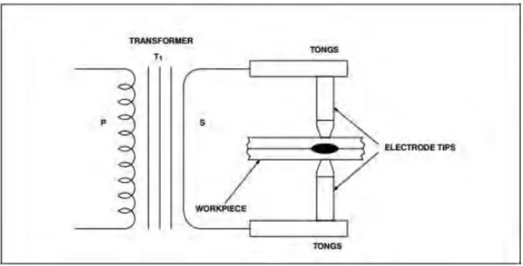
2 RSW process, is a where two or more metal work pieces will be joined by the heat generated by the current through the metal work piece and pressure electrodes. Figure 1.1 below, show an illustration of RSW circuit. The workpiece are held together under pressure between upper and lower electrode. This machine can automatic operation by robotic and manually depend on process and situation. The effect of heat welding mainly depends on three factors; welding time, welding current and contact resistance. For the quality of spot welding depends on the parameters used in accordance with the work piece. Good quality of spot welding depends on these three factor; welding time, welding current and electrode force.
Figure 1.1 : Simple Drawing RSW with Work piece (Luo Yi et al., 2009)
1.2 Problem Statement
3 Based on the investigation conducted by a vehicle involved in an accident at least one passenger suffered a severe injury or death to be hospitalized. Information submitted by the investigation allow vehicle manufacturers to change the shape of their vehicle by changing the materials used in their vehicles to improve the safety of passengers. To reduce the severity of injuries sustained by passengers in the event of an accident involving vehicle design and safety features that enhance the design, materials and safety features that correspond to the metal used (Teng et al., 2008).
Figure 1.2: Statistic total casualties and injuries caused by road, accidents in Malaysia, 2003 -2012.
4 assembly and it can to use for welding metal sheet such as cold roll steel and high strength steel. (Shamsul et al., 2007).
In recent years, a number of analysis and other methods already exist to modernize the welding process to produce quality welds with different process parameters. The study, to see the effect of the three parameters such as welding power, welding time and welding current to a tensile shear strength. In this study, involving two metal combination of HSS and SPCC and most important is a consideration of welding is welding parameters (Hamidinejad et al., 2012). To produce some quality welding automatic welding machines running on the same metal and to show the quality of resistance spot welding is controlled with different parameters to compare the quality of the weld as parameters corresponding to the metal (Tsai et al., 1991).
From the point of view of the reliability of automotive structures, many investigations have been conducted to assess and predict the fatigue strength of spot welded joints. When spot welding two layers of HSS with SPCC electrode usually experience significant depression due to high costs, which in many cases is unacceptable for aesthetic reasons (Nielsen et al., 2011).
5 1.4 Objective
The main objective of this research is investigate the effect of different base metal in RSW by using 2 layer of different base metal in metal sheet spot welding.
I. To prepare the testing workpiece in different base metal.
II. To compare the quality and weldability of welded metal sheet in different base metal.
III. To analyse the microstructure weldabilily of welded metal sheet in different base metal.
1.5 Project Scope
The research is subjected to the following scope:
I. Preparing the testing workpiece using cutter machine and resistance spot welding machine.
II. Investigate the strength of 2 layer welded sheet by using Universal Testing Machine (UTM), Hardness Testing Machine. In this study, the test is making the hardness test and shear tensile test.
III. Scanning Electron Microscope (SEM) for investigate the microstructure of different base between high strength steel (HSS) and cold roll (SPCC).
6
CHAPTER 2
LITERATURE REVIEW
2.0 Introduction
This chapter will explain the theory about spot welding machine, parameters spot welding, types and features material, types of testing machine and theory testing.
2.1 Resistance welding Machine
The welding have many types which usually using in joining two or more steel sheet. Resistance spot welding (RSW) is the predominant welding technique used for joining steel in automotive applications (Khan et al., 2008). An electric current will flow on section are welded with using electrodes highly conductive during the welding process. The force needed to hold metal sheets during process welding. The nugget weld shaped through three parameters is time, heat and pressure. In to making a good quality welding joint, heat is required in sufficient quantities on the surface of metal sheets. Parameters must be in the correct value parameter as force, current and time to get a good weld. The resistance welding process can be classified:-
7 2.1.1 Projection Welding Machine
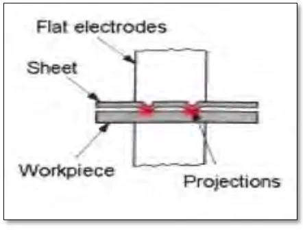
[image:23.612.212.433.317.485.2]Figure 2.1 shown the types of RSW process specially designed of projections in one section. The projection welding process is similar to spot welding except that the welding pressure, and welding current. Hence the welding heat are localized by making projection or embossments on one or both of the work pieces to be joined. Common use of projection welding is the use of special nuts that have projections on the portion of the part to be welded to the assembly. The advantage of the resistance projection welding is more than one spot weld can be made in a single operation, so the operation is very fast and welding current and pressure required is less (Saleem, 2012).
Figure 2.1: Projection Welding.
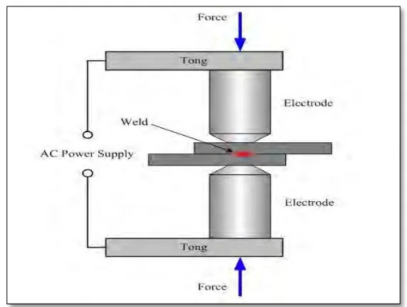
2.1.2 Spot welding Machine
8 welding because the resistance of the metal which need welded and produce heat for joints metal sheets. The required amount of time current flows in the joint is determined by material thickness and type, the amount of current flowing and the cross-sectional area of the welding tip contact surfaces. Heat produced between surfaces normally at surface metal sheets.
Figure 2.2: Spot Welding.
2.1.3 Seam welding Machine