Direct Torque Control Scheme For A Four Switch Inverter Fed
Induction Motor Using Fuzzy Controller
Kancharla Gunamanikanta1, Dr. V Srinivasa Rao2
M.tech Scholar Department of EEE, Aditya Engg. college, Surampalem, India.1 Professor and HOD Department of EEE,Aditya Engg. college , Surampalem, India.2
Abstract— This work implements a new approach of fuzzy logic based space vector regulation with respect to the immediate torque controlled acceptance engine bolstered by four switch three stage inverter (FSTPI) to conquer the downside of high torque swell. This methodology offers superior as far as torque swell lessening partnered to control of inverter exchanging misfortune. The three level hysteresis controller in the torque circle is supplanted by a two level hysteresis controller, with the goal that no zero voltage vector is associated with the proposed DTC plot. This technique depends on the imitating of the operation of the traditional six switch three stage inverter (SSTPI). The FSTPI produces four lopsided voltages intrinsically. With the best possible blend of four lopsided voltages prompting the union of six adjusted voltage vectors of the SSTPI. In the execution of this approach the outline of vector choice table partitions the Clarke plane into six zones. In the actualized DTC conspire enlistment engine is reenacted in stationary reference edge and its outcomes are drawn. Recreation aftereffects of the proposed DTC methodology, FSTPI sustained acceptance engine drives shows fascinating execution.
Index Terms— Balanced voltage vectors, direct torque
control (DTC), four-switch/six-switch three-phase inverter (FSTPI/SSTPI), induction motor (IM) drive, vector selection, Table, Fuzzy controller.
I. Introduction
Over the previous decades DC machines were utilized widely for variable speed applications due to the decoupled control of torque and flux that can be accomplished by armature and field current control separately. DC drives are favorable in numerous viewpoints as in conveying high starting torque, simplicity of control and nonlinear execution. Be that as it may, because of the real downsides of DC machine, for example, nearness of mechanical commutator and brush get together, DC machine drives have turned out to be out of date today in modern applications.
The benefits of asynchronous motor such as the robustness, low cost, the high performance and easy maintenance made utilized as a part of numerous
modern applications. Among a wide range of electric motors squirrel case inductance motor(SCIM) are broadly utilized as they have every one of the benefits of AC engines and less expensive in cost when contrasted with slip ring induction motors. In the absence of slip rings, brushes and cost connected with the wear and tear of the brushes are minimized
Numerous new techniques of control have been created in most recent couple of years to achieve the best performance of induction motor drive. Presently modern high switching frequency power converters, frequency, phase and magnitude of the input to an AC motor can be changed, subsequently the motor speed and torque can be controlled. Today it is conceivable to manage the axis control of machine drives with variable speed in low power applications for the most part because of joint advance of the power electronics and numerical electronics. The dynamic operations of the induction motor drive frames as a critical part on the overall performance of the system.
organizing the arrangement of the vectors, the compensation recurrence is decreased viably without execution corruption [4]. A low pass channel based voltage display with remunerations of sufficiency and stage is utilized secure exact stator flux estimation to further change in the execution of the system.
DTC was first introduced by Takahashi in Japan in 1985 and today this control scheme is considered as the
world’s most advanced AC drives control technology.
This is a simple control technique which does not require coordinate transformation, PI regulators, and pulse width modulator and position encoders. This technique results in direct and independent control of motor torque and flux by selecting optimum inverter switching modes. The electromagnetic torque and stator flux are calculated from the primary motor inputs such as stator voltage and current. The optimum voltage vector selection for the inverter is made so as to restrict the torque and flux errors within the hysteresis bands. The advantages of this control technique are quick torque response in transient operation and improvement in the steady state efficiency.
The primary goal of this project work is to create 1. A control technique so as to accomplish
dynamic response, quick torque response.
2. A controller having low inverter switching frequency , low harmonic losses, high efficiency.
II. DTC OF FSTPI-FED IM DRIVES
Fig.1 Implementation scheme of the DTC strategy using fuzzy logic
In recent years, induction motor control methods have been the field of enthusiasm of numerous analysts to discover diverse answers for induction motor control having the components of exact and speedy torque reaction, and lessening of the multifaceted nature of field situated control. The immediate torque control procedure has been perceived as the basic and suitable answer for accomplish these necessities. DTC is a standout amongst the most fabulous and effective control systems of enlistment engine. This strategy depends on decoupled control of torque and stator flux and today it a standout amongst the most effectively examined control procedures where the point is to control viably the torque and flux.
2.1 Conventional DTC scheme
The existence DTC strategy is a control in closed loop, the vital components of the control structure being the power supply circuit, a three stage voltage source inverter, the enlistment engine, the speed controller to create the torque order and the DTC controller. The DTC controller again comprises of torque and flux estimation square, two hysteresis controllers and area choice piece, the yield of the DTC controller is the gating beats for the inverter.
The DTC conspire does not require facilitate change as all the control strategies are completed in stationary casing of reference. So this plan does not experience the ill effects of parameter varieties to the degree that other control methods do. Likewise there is no criticism current circle because of which the control activities don't experience the ill effects of defers characteristic in the present controllers, no heartbeat width modulator, no PI controller, and no rotor speed or position sensor. So it is a sensor less control method which works the engine without requiring a pole mounted mechanical sensor. Here on line torque and flux estimators are utilized for shutting the circle. Here the torque and stator flux are controlled specifically by utilizing hysteresis comparators. Fig2 demonstrates the fundamental square outline of routine DTC plot.
2.2 Principle of DTC scheme
Fig.2 Block diagram of conventional DTC scheme for IM drives
As we probably am aware from the past section that a three stage VSI has eight conceivable blends of six exchanging gadgets which is appeared in Fig.3. The six switches have a very much characterized state ON or OFF in every setup. So all the conceivable arrangements can be related to three bits (Sa, Sb, Sc) one of every inverter leg. The bit is set to 1 if the top switch is shut and to 0 when the base switch is shut. To counteract short out of the supply, the condition of the upper switch is constantly inverse to that of the lower one.
Fig.3 Simplified three phase VSI 2.3 Direct flux control
In stationary reference frame the stator flux equation can be written as
In the stator resistance drop is neglected for simplicity, the stator flux varies along the direction of applied voltage vector and the equation will be reduced to
Which implies by applying stator voltage
vector V ̅_s for a period increase Δt , Ψ ̅_s can be changed incrementally. The summon estimation of the stator flux vector 〖ψ ̅_s〗^* takes after a roundabout direction, the plane of stator flux is isolated into six parts as appeared in Fig.4 Every part has an alternate arrangement of voltage vector to increment or diminishing the stator flux. The charge flux vector pivots in anticlockwise course in a roundabout way and the genuine stator flux vector Ψ ̅_s tracks the summon flux in a crisscross way however obliged to the hysteresis band which is appeared in Fig.4. As a rule the dynamic forward voltage vector (V_(s,k+1) and V_(s,k+2) ) are connected to increment or diminishing the stator flux separately when the stator flux lies in area k. the radical voltage vectors (V_(s,k ) and V_(s,k+3)) which rapidly influence the flux are for the most part kept away from. The dynamic turn around voltage vectors (V_(s,k-1) and V_(s,k-2) are utilized to increment or diminishing the stator flux backward bearing.
The stator flux vector change because of stator voltage vector in fast where as change rotor flux is drowsy as a result of its extensive time constantT_r, that is the reason Ψ ̅_s development is jerky and Ψ ̅_r
moves consistently at recurrence ω_e as it is more separated. However the normal speed of both continues as before in unfaltering state condition.
The electromagnetic torque produced due to interaction of stator and rotor flux is given by the following equation.
Fig.5 stator flux, rotor flux and stator current
vectors in reference plane
From the above unmistakably torque fluctuates straightforwardly as edge between stator flux and rotor flux i.e. γ. So keeping in mind the end goal to
acquire high element execution it is required to change
γ rapidly. Accepting the rotor is turning in
anticlockwise course persistently and stator flux lies in part k, the dynamic forward voltage vectors (V_(s,k+1)
and V_(s,k+2) ) are connected to increment γ so as the
torque Te. The outspread voltage vectors (V_(s,k ) and
V_(s,k+3)) are utilized to diminish γ and Te. By
applying the invert dynamic voltage vectors (V_(s,k-1) and V_(s,k-2) ) torque can be diminishing quickly. The two zero voltage vectors (Vs, 0 and Vs, 7) are connected to keep up the flux consistent in a perfect world and to diminish the torque marginally.
Switching selection
An elite torque control can be built up due to the decoupled control of stator flux and torque in DTC. Fig.6 demonstrates a case of stator flux situated in part -1 with the relating ideal exchanging voltage vectors for hostile to - clockwise and clockwise pivot of the pole.
Ideal exchanging vector determination table given by Table 2.1 demonstrates the ideal choice of the exchanging vectors in all areas flux arrange. This table depends on the estimation of stator flux mistake status, torque blunder status and introduction of stator flux for counter clockwise turn of the pole.
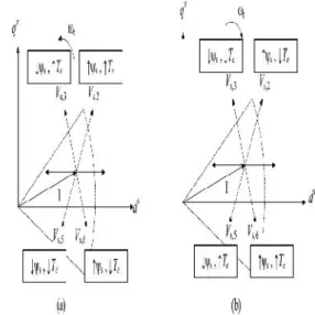
Fig.6 Optimum switching voltage vector in sector 1 for (a) anti-clockwise and (b) Clockwise
rotation
Table 2.1 Applied selected voltage vectors
Stator flux estimation
For correct figuring of stator flux and torque blunders, an exact estimator of stator flux is fundamental. There are generally utilized techniques for estimation of flux to be specific stator voltage model and current model.
Stator voltage model
This is the most straightforward strategy for stator flux estimation, where the machine terminal voltages and streams are detected and from the stationary edge proportional circuit the fluxes are registered.
This strategy gives precise flux estimation at fast yet in mechanical applications requiring vector drives at zero start-up this technique can't be utilize d on the grounds that at low speed stator resistance drop gets to be distinctly huge bringing on incorrect estimation. Additionally at low recurrence, voltage signs are low and dc balance tends to develop at the coordination yield, therefore perfect combination gets to be distinctly troublesome.
Current model
In stationary reference outline, current model is universally steady and the drives operation can be stretched out down to zero speed. Be that as it may, this model is much mind boggling when contrasted with voltage demonstrate as here the learning of rotor speed and stator current is required to gauge rotor flux linkage and stator flux can be evaluated in light of the estimation of rotor flux linkage. From the dynamic conditions of IM in stationary reference casing, stator and rotor flux can be inferred which are given underneath
Here the conditions include shut circle mix, so there is no reconciliation float issue in current model at low speed area. However estimation precision is influenced because of engine parameter variety, especially rotor resistance variety gets to be distinctly overwhelming by skin impact and temperature.
III. Fuzzy logic
Fuzzy logic is about the relative significance of accuracy: How vital is it to be precisely right when an unpleasant answer will do? You can utilize Fuzzy Logic Toolbox programming with MATLAB specialized registering programming as a device for taking care of issues with fluffy rationale. Fluffy rationale is a captivating territory of research since it benefits an occupation of exchanging off amongst noteworthiness and accuracy something that people have been overseeing for quite a while. In this sense, fluffy rationale is both old and new in light of the fact that, in spite of the fact that the cutting edge and efficient study of fluffy rationale is still
youthful, the idea of fluffy rationale depends on age-old aptitudes of human thinking.
Fuzzifier changes over a numerical variable into a semantic mark. In a shut circle control framework, the blunder (e) between the reference voltage and the yield voltage and the rate of progress of mistake (del e) can be marked as zero (ZE), positive little (PS), negative little (NS), and so on. In this present reality, measured amounts are genuine numbers (fresh). The FLC takes two sources of info, i.e., the mistake and the rate of progress of blunder
In view of these information sources, The FLC takes a canny choice on the measure of field voltage to be connected which is taken as the yield and connected straightforwardly to the field twisting of generator. Triangular participation capacities were utilized for the controller.
IV.Simulation results
Time(s)
Fig.4.1(a) Stator voltage Vas(V), (b) Stator voltage Vcs(V), (c) Sta tor currents(A)
Fig.4.2 (a) Sectors, (b) Stator flux (mWb), (c) Torque(Nm)
V.CONCLUSION
In this project, a new fuzzy logic based space vector modulation method has been implemented for the DTC controlled induction motor drivers and aim of the approach is to overcome high torque ripple disadvantages of basic direct torque control. The Modified DTC methodology depends on the imitating of the strategy of the routine SSTPI. This has been perceived with the suitable blends of the four unequal voltage vectors in a general sense created by the FSTPI, prompting to the amalgamation of the six adjusted voltage vectors delivered by the SSTPI. This progress has been received in the arrangement of the vector choice table which is just tended to by hysteresis controllers, considering a division of the Clarke plane into six zones.
Recreation based examinations of the IM enduring state highlights have uncovered the elite of the presented DTC methodology. In the venture, the enlistment engine has been recreated for appraised speed (1380 rpm reference) working conditions to accomplish pixie examinations for both PI and Fuzzy control strategy.
REFERENCES
[1] Bassem El Badsi, Badii Bouzidi, and Ahmed Masmoudi “DTC Scheme for a Four-Switch Inverter-Fed Induction Motor Emulating the Six-Switch Inverter Operation,” IEEE Trans. Ind. Appl., vol. POWER ELECTRONICS, VOL. 28, NO. 7, JULY 2013
[2] Y. Zhang and J. Zhu, “Direct torque control of
permanent magnet synchronous motor with reduced
torque ripple and commutation frequency,” IEEE Trans. Power Electron., vol. 26, no. 1, pp. 235–248, Jan. 2011.
[3] Y. Zhang, J. Zhu, Z. Zhao, W. Xu, and D. G.
Dorrell, “An improved direct torque control for three
-IEEE Trans. Power Electron., vol. 27, no. 3, pp. 1502–
1513, Mar.2012.
[4] A. Taheri, A. Rahmati,and S. Kaboli, “Efficiency
improvement in DTC of six-phase induction machine
by adaptive gradient descent of flux,” IEEE Trans. Power Electron., vol. 27, no. 3, pp. 1552–1562, Mar. 2012.
[5] A. B. Jidin, N. R. B. N. Idris, A. H. B. M. Yatim, M. E. Elbuluk, and T. Sutikno, “A wide-speed high torque capability utilizing over modulation strategy in DTC of induction machines with constant switching
frequency controller,” IEEE Trans. Power Electron., vol. 27, no. 5, pp. 2566–2575, May 2012.
[6] J. K.Kang, D. W. Chung, and S. K. Sul, “Direct
torque control of induction machine with variable amplitude control of flux and torque hysteresis
bands,” in Proc. Int. Elect. Mach. Drives Conf., Seattle, Washington, May 1999, pp. 640–642.
[7] K. B. Lee and F. Blaabjerg, “Sensor less DTC -SVM for induction motor driven by a matrix converter
using a parameter estimation strategy,” IEEE Trans. Ind. Electron., vol. 55, no. 2, pp. 512–521, Feb. 2008.
[8] Z. Zhifeng, T. Renyuyan, B. Boadong, and X.
Dexin, “Novel direct torque control based on space vector modulation with adaptive stator flux observer for
induction motors,” IEEE Trans. Magn., vol. 48, no. 8, pp. 3133–3136, Aug. 2010.
AUTHORS:
Kancharla Gunamanikanta currently purshuing M.Tech, Power Electronics And Drives,Department Of Electrical And Electronics Engineering,Aditya Engineering College, Surampalem. East Godavari,A.P His interested areas are Electrical Machines, power electronics and drives.
DR. V. SRINIVASA RAO,Currently working as a Professor And Head Of The Department Of Electrical And Electronics Engineering, Aditya Engineering College, Surampalem. East Godavari,A.P. His interested areas are Electrical Machines, power electronics and Power systems.
.