Design of 3-stage Parallel Cascade Micro-ring Resonator Type
of Interleave Filter
for Optical Communication Application
Desain dari Filter
Interleave
jenis
Parallel Cascaded
Microring Resonator
3 tingkat
untuk Aplikasi Komunikasi Optik
Yudi Yuliyus Maulana
*and Dadin Mahmudin
Research Center for Electronics and Telecommunication - Indonesian Institute of Sciences (LIPI) Komplek LIPI Gedung 20 Lantai 4, Jl Sangkuriang, Bandung 40135, Indonesia
Abstrak
Filter will be one of the most important components of the next generation of optical communications. Micro-ring resonators have been widely studied as a potential device for dense wavelength filter due to its advantages. In this paper, a waveguide-based microring-resonator type of interleave filter is investigated. The cascade structure is applied to obtain better characteristics of filter spectra. Our calculation shows that, compared with 2-stage or 4-stage cascade, 3-stage cascaded micro-ring resonator has better performance with pass-band width of 22 GHz, ripple ratio < 1 dB, crosstalk of -33 dB for 1×2 interleaver and -24 dB for 1×4 interleaver. Numerical calculation also clearly shows that general optical waveguide types is reasonable as microring resonator with insertion loss < 2 dB.
Keywords: interleave filter, wavelength splitter, microring resonator.
Abstract
Komponen filter merupakan komponen yang sangat penting untuk aplikasi sistem komunikasi optik di masa yang akan datang. Micro-ring resonator telah dipelajari secara luas sebagai devais yang mempunya potensi sebagai filter karena kelebihan-kelebihannya. Dalam makalah ini telah diteliti filter interleave tipe Parallel Cascaded Micro-ring Resonator (PCMR). PCMR merupakan struktur Micro-ring resonator yang terdiri beberapa ring disusun secara paralel dengan tujuan untuk memperoleh karakterisasi terbaik. Dari hasil perhitungan memperlihatkan bahwa dibandingkan dengan PCMR dengan 2 ring dan PCMR dengan 4 ring, PCMR dengan 3 ring mempunyai performa yang lebih baik dengan lebar pass-band sebesar 22 GHz, ripple ratio < 1 dB, crosstalk sebesar -33 dB untuk 1×2 interleaver dan -24 dB untuk 1×4 interleaver. Dari perhitungan numerik dengan jelas memperlihatkan bahwa umumnya jenis optical waveguide adalah wajar sebagai micro-ring resonator yang mempunyai nilai insertion loss < 2 dB.
Kata kunci: filter interleave, wavelength splitter, micro-ring resonator.
I. INTRODUCTION
Explosive growth in the internet requires larger channel capacity. Dense wavelength-division multi-plexing (DWDM) is an important solution for this demand. This growth requires high performance of optical devices. One of key devices for DWDM is wavelength filter. Recently, DWDM has had channel spacing narrower than 100GHz. In order to satisfy this requirement, waveguide-based filters are proposed. A concept of interleave filter or interleaver (or wavelength splitter) was also introduced to DWDM system with channel spacing <50 GHz using Mach-Zhender Inter-ferometer [1]. In addition to the type of MZI, there are several types of filters are investigated in the past few years such as array wave guide (AWG), Fiber Brag
Grating (FBG), Fabry-Perot Interferometer (FPI) etc. [2].
Micro-ring resonators (MRR) have been widely studied as a potential device for communication applicatios due to its advantages in smaller size and can be integrated with other devices [3]. The other advantage of the MRR is easily modified into another form (structure of MRR) to increase the performance. Therefore, in addition to communication applications, MRR can be used for sensor applications with a high level of sensitivity [4], [5].
In this paper, our investigation of interleaver by using cascaded microring resonator is reported. Since microring resonators have 2 outputs, i.e. resonance output and antiresonance output, and also have periodic spectrum characteristics, they are applicable for interleavers. Another advantage of a microring resonator inter leaver is that the denser DWDM channel will require larger ring radius. As a result, bending loss is negligible because the bending loss decreases with increasing ring radius. Based on optical lattice structure
* Corresponding Author. Email: [email protected]
Received: November 18, 2015; Revised: November 28, 2015 Accepted: December 5, 2015
Published: December 30, 2015 2015 PPET - LIPI
Figure 2. -1 dB Bandwidth and Ripple Ratio Characteristics for 2-Stage Cascade Microring Resonator,
Attenuation Factor α = 0 dB/cm.
(a) (b)
Figure 1. (a) 3-Stages Cascade Micro-ring Resonator Structure, (b) Block Diagram for Our Analysis.
theory [6], the cascade structure is provided to obtain better characteristics.
II. DEVICE MODELING
Figure 1 (a) shows an example of 3-stage cascade of micro-ring resonator with ring radius r. Out-1 and Out-2 are anti resonance and resonance outputs, respectively. In 12 interleavers, one outport is used to passthrough odd channels and the other port pass-throughs even channels. Figure 1 (a) illustrates that resonance wavelength is set to even channels.
Power coupling ratios from input waveguide to ring and from ring to output waveguide are denoted by K1 and K2, respectively. Power coupling ratios between two rings are denoted by K3 and K4. The couplings between waveguide and ring, and between two rings are assumed as symmetric directional couplers.
There are some methods to analyze micro-ring resonator. Finite difference time domain (FDTD) method is usually used if both time and space response of fields are required. However, it will consume much memory and calculation time. In this study, since only the steady-state characteristic of microring resonator is needed, transfer matrix method [7], [8] is simpler to be used. Signal flow chart is also applied to derive transfer function of cascaded microring resonator. Figure 1 (b) shows block diagram of 3-stage micro-ring resonator consisting of transfer matrices of directional coupler Hci
(where the subscripts i = 1, 2 are for input and output couplers, and i = 3, 4, .. are for couplers between two rings) and factor of delay lines R. Equations of Hci and R are defined in the following equations:
, ,12,3,..
1 1 i K K j K j K H i i i i ci (1)
R
e
j(j)pr (2) where b, a, and r are propagation constant, attenuation factor of waveguides and ring radius, respectively. In this analysis we assume that propagation constants ofring and input-output waveguides are same. The waveguides are also assumed as single mode. The excess loss of coupler is also neglected. Figure 1(b) can be expressed in terms of 4-ports network equation as follows: 2 1 22 21 12 11 2 1 a a H H H H b b (3)
where b1, b2 and a1 are complex amplitude of electric field in Out-1, Out-2 and input ports, respectively. In this study a2 is zero. The elements of the transfer function (H11, H12, H21and H22), which a function of Ki, b, and a, can be derived by using signal flow chart. In this paper, evaluating of spectra characteristics is based on the transmittance spectrum of Out-2 (resonance output).
III. ANALYSIS RESULTS
In general, wavelength filters for DWDM are re-quired to have the following optical characteristics: (1) low channel crosstalk; (2) wide bandwidth with low ripple and box-like spectra; (3) low insertion loss. Assuming LN proton exchange waveguide, our study evaluated those performances of cascaded microring resonator. The FSR of microring resonator is assumed 100 GHz. It means that the device works as 1×2 inter-leaver for 50 GHz channel spacing.
A. Selection the Values of K1 and K2
Figure 3. Crosstalk Characteristics for 2-Stage Cascade Micro-ring Resonator (α = 0 dB/cm).
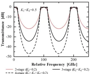
Figure 4. Spectra Characteristics for Various Stages of Cascade Microring Resonator (α =0 dB/cm).
Figure 5. Dependence of Crosstalk on K3 (= K4 = K5)
for α = 0 dB/cm.
Figure 6. -1 dB Bandwidth Characteristics Depending on Power Coupling Ratio K3 (= K4 = K5) for α = 0 dB/cm.
the crosstalk degrades with increasing K1 (= K2). Based on Figure 2 and Figure 3, we choice K1 = K2 = 0.5 which shows low ripple with relatively wide pass-band. In the cavity structure, Q-factor will degrade if stored energy in cavity decreases. Increasing K1 (= K2) corresponds to decreasing stored energy in ring resonator. Therefore, we limit K1 = K2 up to 0.5. The crosstalk performance can be improved by cascade structure, as it will describe in the next section.
B. Crosstalk Performance
Since the FSR of the ring is 100 GHz, channel crosstalk is calculated between peak level of center frequency (or wavelength) and spectrum level at 50 GHz separation. Although the value of channel crosstalk should be as low as possible, the target was set to be 25 dB.
Figure 4 shows spectra characteristics for 2-stage, 3-stage and 4-stage cascade where the spectra level at 50 GHz separation from peak become lower with increasing the number of stages.
Figure 5 shows crosstalk characteristics depending on power coupling ratio between two rings K3, K4 and K5, which are chosen to be equal each other. Crosstalk degrades with increasing K3 (= K4 = K5). For crosstalk of < -25 dB, we obtain values of K3 (= K4 = K5) as follows: (1) K3 < 0.1 for 2-stage structure; (2) K3 (= K4) < 0.48
for 3-stage structure; (3) K3 (= K4 = K5) < 0.71 for 4-stage structure. These values will be used as references to determine the best choice of the stage number in the next section.
C. Spectrum characteristics
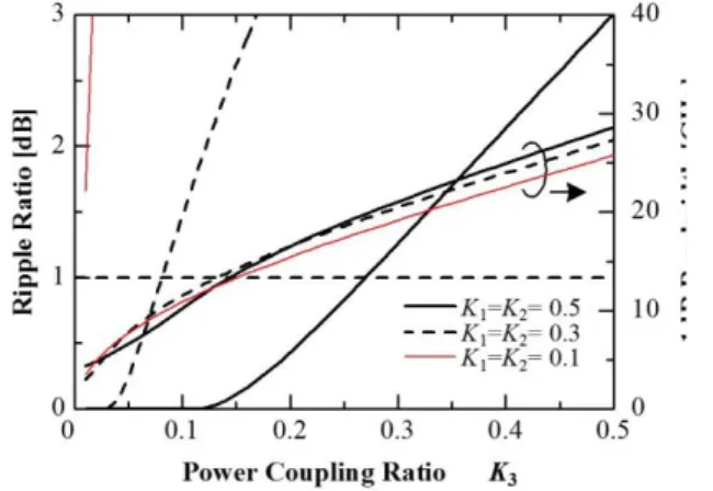
General requirement for high-speed device is wide pass-band. The dependence of top passband width (at -1 dB) on power coupling ratio K3 (= K4 = K5) for various stages is summarized in Figure 6. This figure shows that wide pass-band can be realized by increasing value of K3 (= K4 = K5). Other parameters for evaluating the quality of spectra are ripple ratio and box-like spectrum. Ripple ratio should be as low as possible. The commercial value of ripple ratio is < 1 dB. On the other hand, in order to express box-like spectrum, we introduce “shape factor” parameter, which defined as a ratio of bandwidth at -1 dB and bandwidth at -20 dB. The ideal value of shape factor is 1.
Figure.7. Ripple ratio and shape factor characteristics for α = 0 dB/cm.
Figure 8. Crosstalk Characteristics for Various Changes of Loss.
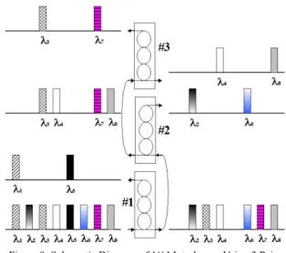
Figure 9. Schematic Diagram of 1×4 Interleaver Using 3 Pairs Cascaded Micro-ring Resonator.
Referring to the previous result at section 3.2 (crosstalk performance), although 4-stage has better performance on crosstalk, it does not provide better performance on bandwidth and ripple. As a result, it can be concluded that 3-stage cascade structure is the best choice for high-speed operation with low crosstalk and low ripple as summarized in Table 1. We also obtain that shape factor for 3-stage cascade at K3 = K4 = 0.22 (the best choice for high operation) is 0.51.
TABLE 1.CROSSTALK AND MAXIMUM BANDWIDTH FOR 1DBRIPPLE REQUIREMENT.
D. Effect of propagation loss
Considering the loss effect is important to design optical devices. Recent optical waveguides, such as LN proton-exchange waveguide, have propagation loss below 1 dB/cm [5]. Moreover, ring resonator has bending loss due to bending waveguide. By insertion various values of α in our analysis, the result shows that the performances of microring resonator degrade with increasing loss. Figure 8 shows degradation of crosstalk performance due to waveguide loss α. The waveguide loss also affects to insertion loss of devices directly. Our calculation shows that in order to obtain insertion loss < 2 dB, waveguide loss is permitted up to ~4 dB/cm for 3-stage cascade. It means that general types of optical waveguides (LN, semiconductor or PLC) are available as cascaded micro-ring resonator.
E. 1×4 Interleaver
The results described above are based on 1×2 interleaver. In this section we will discuss availability of microring resonator for 1×4 interleaver. The schematic figure of 1×4 interleaver, which consists of 3 pairs of 3-stage cascaded microring resonator, is shown in Figure 9. In Table 1, it is shown that pass-band width of cascaded microring resonator is around 20 GHz. With this level of bandwidth, microring resonator is actually more reliable as 1×4 interleaver. For 100 GHz-FSR of microring, 1×4 interleaver works to split 25 GHz channel spacing into 100 GHz spacing. Basically, all characteristics evaluated at 1×2 interleaver do not change except crosstalk performance. We obtain that crosstalk of 3-stage cascade with the best performance described in Table 1 is -24 dB for 1×4 interleaver.
SUMMARIES
Design of 3-stages Parallel Cascade Micro-ring-Resonator Type of Interleave Filter is investigated. 3-stage cascade is the best choice for pass-band of 22 GHz, ripple ratio < 1 dB and shape factor of 0.51. The crosstalk of 1×2 interleaver is -33 dB, and -24 dB for 1×4 interleaver. For the system permitting 2dB insertion loss, all optical waveguides with loss < 4 dB/cm are available to be realized as microring resonators. In the future, the results of this simulation, will be investigated and fabricated with different materials such as SiO2, Polymer.
ACKNOWLEDGEMENT
This research was supported by Research Center for Electronics and Telecommunication - Indonesian Institute of Sciences (PPET - LIPI) through DIPA Project funding.
REFERENCES
[1] M. Oguma, K. Jinguji, K. Kitoh, T. Shibata and A. Himeno, “Flat-passband interleave filter with 200GHz channel spacing based on planar lightwave circuit-type lattice structure”, Elec. Lett., 36, pp.1299-2000, 2000.
[2] D. Heard, “Tunable filter technology improves fiber optics and DWDMs”, Europhotonics, pp. 44-45, June/July, 2000. [3] B. E. Little, S. T. Chu, H. A. Haus, J. Foresi and J.P. Laine,
“Microring resonator channel dropping filters”, J. Lightwave Technol., 15, pp. pp.998-1005, 1997.
Power Coupling Ratio
Crosstalk (dB)
Max. Bandwidth at -1 dB
(GHz)
2-stage K3=0.28 -20 20
3-stage K3=K4=0.22 -33 22
[4] D. Mahmudin, T. T. Estu, P. Daud, N. Armi, Y. N. Wijayanto and G. Wiranto, “environmental liquid waste sensors using polymer multi-coupled ring resonators”, in Proceedings of International Conference Smart Sensor and Application, May 2015.
[5] D. Mahmudin, T. T. Estu, P. Daud, I. D. P. Hermida, G. Sugandi and Y. N. Wijayanto, “Sensitivity improvement of multipath optical ring resonatore using silicon-on-insulator technology”, in Proceedings of10th IEEE Regional Symposium on Micro and Nanoelectronics (RSM), August 2015.
[6] K. Jinguji and M. Kawachi, “Synthesis of coherent two-port lattice-form optical delay line circuit”, J. Lightwave Technol., 13, pp.73-82, 1995.
[7] J. Capmany and M. A. Muriel, “A new transfer matrix formalism for the analysis of fiber ring resonator: compound coupled structures for FDMA demultiplexing”, J. Lightwave Technol., 8, pp.1904-1919, 1990.