Abstract— A new shunt reactive power compensator, CSCT, is presented and introduced in this paper. Mathematical analysis of harmonic content of the current of the CSCT is performed and use of a three-winding transformer with additional circuit is presented as a solution to suppress these harmonics.
Index Terms—Harmonic performance, CSCT, Tuned LC-filter, Reactive power.
I. INTRODUCTION
The controlled shunt compensator of transformer type (CSCT) can be used as a general compensator like the scheme that is presented in Fig. 1. This configuration is a transformer with three windings. The network winding (NW) is connected to the network high voltage bus, and is the main winding of the compensator. The controlled winding (CW) is the second winding in which a thyristor valve (TV) in parallel with a voltage circuit breaker (VCB) are connected across the secondary. The third winding is the compensating winding (ComW) which is indicated as the tertiary winding in Fig. 1. Two tuned harmonic filters and a capacitor bank are connected across this winding. It is important to note that the CSCT is a three phase compensator. Both the three-phase NW and CW is of star-connected type, and the neutral is grounded. However the three-phase ComW can be of delta-connected type.
Figure 2 represents one phase of the transformer with mentioned three windings. The winding close to the main core is CW, the outer winding is NW and interlayed winding is ComW. The reason to place the ComW between the NW and the CW is discussed later on in this paper.
Manuscript received October 9, 2006. This work was done at powe quality and reactive power laboratory of the K. N. Toosi University of Technology.
M. Tavakoli Bina is with Electrical Engineering Faculty, K. N. Toosi University of Technology, PO Box 16315-1355, Tehran-Iran (phone: +98(21)-8846-9084; fax: +98(21)-8846-2066; e-mail: tavakoli@ kntu.ac.ir). G.N.Alexandrov is with Electrical Engineering Department, Saint-Petersburg State Technical University, Russia (e-mail: [email protected]).
M.Golkhah is with the Electrical Engineering Faculty, K. N. Toosi University of Technology, Tehran-Iran (e-mail: [email protected]).
When the TV is open all the magnetic flux passes through the magnetic core, leading to a minimum reluctance, maximum inductive and capacitive current in NW according to the value of capacitor bank. This eventually injects reactive power to the network. Further, when the TV is closed the flux is subjected to pass through the air gap including all of the windings. Hence the reluctance, inductance and the current of the NW will be maximal; minimal and maximal inductive (the rated value), respectively. Since two modes lead to two different signs in reactive power, the compensator can practically operates both in capacitive and reactive modes.
However the capacitor can be removed from the compensating winding still having bilateral reactive power compensation if the relationships of designing elements of harmonic filters be correctly performed. These relations are calculated and presented below.
II. MATHEMATICAL ANALYSIS TO CALCULATE HARMONIC
COMPONENT OF THE CSCT CURRENT
Applying thyristors to control the current of the compensator brings highest harmonics in the current. Highest harmonics are formed during incomplete combustion angle of thyristors when current flows intermittently through
Harmonic Study and Suppression on the Current
of CSCT
[image:1.595.306.550.388.557.2]Mohammad Tavakoli Bina, G.N.Alexandrov and Mohammad Golkhah
= −
+ ⋅ − ⋅
= 1 [( 2 ) (1 2sin ) 3sin2 ] )
( π ψ 2ψ ψ
π ψ
I I
thyristor block. With angles 0≤ωt≤ψ and π−ψ ≤ωt≤π the current equals zero, and with angles ψ<ωt<π−ψ,
(
sinω sinψ)
)(t =I ⋅ t−
i m
Where the firing angle
ψ
can change in the range of2 /
0<ψ<π . The root-mean-square current (effective current value) through the thyristor for half-cycle of main frequency is:
= −
⋅
=
∫
−ψ π
ψ
ψ π
ψ I wt dwt
I m (sin sin )2
1 )
(
] 2 sin 5 , 1 ) sin 5 , 0 ( ) 2 [(
1 π ψ 2ψ ψ
π⋅ − ⋅ + −
⋅ =Im
The ratio of the root-mean-square current through the thyristor at arbitrary firing angle ψto the root-mean-square of rated current I=Im/ 2(corresponding with angleψ=0)
equals to:
] 2 sin 3 ) sin 2 1 ( 2
1 2 ψ
π ψ π
ψ ⋅ + − ⋅
⎟ ⎠ ⎞ ⎜ ⎝ ⎛ − =
The current through the thyristor block decreases fast with increase in ignition angle (see Fig. 3). Thus the content of the higher harmonics strongly changes with change in ignition angle and can be calculated by the formula
ψ ψ π
ψ ψ
2 sin 2
1 ) 1 sin( 1
) 1 sin( 2
1 .
. − − +
⋅ + + −
⋅ − ⋅ =
= k
k k
k
k I I
k k
к
h
Where Ik and I1 are amplitudes of the k-th harmonic and the fundamental component.
[image:2.595.50.231.316.394.2]Results of calculations with this formula are shown in Fig. 3. As it can be seen from Fig. 3, increase in the number of harmonics leads to decrease in its content. Thus the content of the third harmonic in the current continuously increases with reduction in combustion time of thyristors (increase in firing angle of thyristors). With small firing angles of thyristors (greater combustion angles), the increase in the content of the fifth harmonic is replaced by a reduction down to zero when firing angle ψ=0.22π and then increases again approaching 100 % under a very small reactor current. The content of the seventh harmonic passes through the minimum (zero) twice and then sharply increases approaching 100 % (Fig. 3).
The ratio of current corresponding to the highest harmonics to that of rated reactor current (to current when thyristors are completely opened) has entirely different character. For the third harmonic this attitude reaches a maximum when the reactor current is I=0.42Inom (see curves 1 and 4 Fig. 3b). For the fifth harmonic the maximum is reached at the current I =0.63Inom (see curves 2 and 4 of
Fig. 3b). For the seventh harmonic it is reached when reactor currentI =0.72Inom. The second maximum of the fifth harmonic is much less than the first. The second and third maximum of the seventh harmonic is also much less than the first.
Value of the first maximum in relation to amplitude of rated current, are resulted in table I (designated by the letterβk).
Special winding in delta connection (compensating winding) is usually used for the compensation of the highest harmonics (third). In this case for the third harmonic this compensatory winding is short-circuit, that excludes the possibility of third harmonics in magnetic flux enveloping the compensation winding.
[image:2.595.304.546.337.509.2]There are circuit designs for fifth and seventh harmonics suppression. But they are very complex and expensive. The most simple, cheap and reliable enough design is the application of filters of higher harmonics, connected to compensating windings of each of the phases. Each of such filters consists series-connected reactor (with stable inductance) and capacitors selected in such a way that they provide compensating winding short-circuit for each of the harmonics. Thus the corresponding harmonic cannot be hold in the magnetic flux engulfing compensating winding. The
Figure 2: Single-phase diagram of CSCT: a- view form side; b- view form above: 1- a main core, 2- yokes, 3- lateral yokes, 4- NW, 5- CW, 6- ComW, 7- magnetic shunts.
Figure 3: The ratio of currents of the highest harmonics: third (1). fifth (2), seventh (3) to the current of the fundamental frequency depending on ignition angle of thyristors 0<ψ<900: (a) in relation to present
current of basic frequency; (b) in relation to rated current (when thyristors are completely closed); 4-ratio of root-mean-square value of full current to rated current.
(2-2)
(2-3)
[image:2.595.62.210.475.511.2] [image:2.595.306.548.544.705.2]filter can also provide compensation of the third harmonic component of a single phase reactor.
Since the source of highest harmonics in reactor current is the control winding with thyristors, the compensating windings should cover it to exclude the possibility of keeping higher harmonics in magnetic flux and by that in the current of the network winding covering the control winding and compensating winding.
Thus for the compensation of the k-th harmonic in the current, CSCT should adhere to the equality
k k C k L k ω
ω = 1
From there
k
k k L
C
ω ω = 21
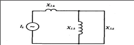
Thus under no-load conditions when control block thyristors are closed (Fig. 4), the ComW of the CSCT is loaded by the impedance
2 2 2 , 1 1 1 ) 1 ( 1 k k C k L C L X k k k k k − = − ⋅ = − = ω ω ω ω
Conformably the fundamental frequency current in control winding current of CSCT, due to filter of k-th harmonic, equals ⎟ ⎠ ⎞ ⎜ ⎝ ⎛ − ⋅ + = − ⋅ + = + = 1 1 1 ) 1 ( 2 2 , 1 , 1 k C Х U k L Х U Х Х U I k nom ph k nom ph k nom ph k ω δ ω δ δ
WhereδXnom defines the short-circuit impedance of the basic winding in relation to ComW with filters and Xnom also defines the rated short-circuit impedance of the basic winding in relation to control winding (CW). Since the optimal impedance value X1, k is greater than impedance δXnom (see below), the current through the filter has capacitive character and the ratio of current I1.k to rated current has a negative sign. k nom nom k k nom nom k nom nom nom k C Х Х k C Х Х k L Х Х I I ω δ α ω δ ω δ 1 1 1 1 ) 1 ( 2 2 , 1 − ≈ − = ⎟ ⎠ ⎞ ⎜ ⎝ ⎛ − ⋅ + = − ⋅ + =
Where αk is the absolute value of the ratio of basic frequency current through the k-th harmonic filter to rated reactor current.
Resolving equation (2-9) in relation toωLk, we get
) 1 ( 1 2− ⋅ + ⋅ = k Х L k k nom k α δ α ω
Capacitor impedance of the k-th harmonic filter to power current according to (2-6), (2-10) equals to:
) 1 ( ) 1 ( 1 2 2 − ⋅ + ⋅ ⋅ = k k Х C k k nom k α δ α ω
Power of the k-th harmonic filter chokes, due to basic frequency current is:
) 1 ( 1 2 2 2 2 .
1 ⋅ −
+ ⋅ ⋅ ⋅ = ⋅ ⋅ = k Х I L I Q k k nom nom k k k
Lk α
δ α α
ω
Capacitor power of the same filter is:
) 1 ( ) 1 ( 1 2 2 2 2 2 .
1 ⋅ −
+ ⋅ ⋅ ⋅ = ⋅ ⋅ = k k Х I C I Q k k nom nom k k k
Ck α
δ α α
ω
Total absolute k-th harmonic filter power due to basic frequency current 1 ) 1 )( 1 ( 2 2 2 . − + + ⋅ ⋅ = + =
∑ Q Q Q kk
Q k
nom k C L
k k k
δ
α
α
Where the rated power of one phase of the reactor equals
nom nom
nom I X
Q = 2 ⋅
The maximum current of the k-th harmonic through the filter of that harmonic can be calculated analytically and defined according to (2-4) by
nom k
k
I
I
=
β
⋅
Accordingly total absolute power of k-th harmonic filter, due to current of k-th harmonic
= ⋅ ⋅ ⋅ = ⎟⎟ ⎠ ⎞ ⎜⎜ ⎝ ⎛ ⋅ ⋅ + ⋅ ⋅ ⋅
= k k
k k
k k
k I k L
C k L k I Q ω ω ω 2 2 . . 2 1 ) 1 ( ) 1 ( 2 ) 1 ( ) 1 (
2 2 2
[image:3.595.49.289.48.200.2]2 2 2 − ⋅ ⋅ + ⋅ ⋅ ⋅ = − ⋅ ⋅ + ⋅ ⋅ ⋅ ⋅ = k k Q k k X I k k nom k k k nom nom k α δ α β α δ α β
Total absolute power of k-th harmonic filter, due to currents of basic and k-th harmonics equals to:
⎥ ⎦ ⎤ ⎢
⎣ ⎡
⋅ + + ⋅ ⋅ −
⋅ + ⋅ = + =
k k k
k nom k k k k
k k
k Q Q Q Q
α β α
δ
α 2 2
2 .
1
. 1 (1 ) 2
1
We shall find the optimum value Qk by equating zero derivative of Qk on
α
k
0 )
1 ( 2 2
1 1
1 2
2 2 2
2 ⎥⋅ =
⎦ ⎤ ⎢
⎣ ⎡
+ ⋅ ⋅ + ⋅ ⋅ − + ⋅ − = ∂ ∂
nom k
k k k
k k k k Q
k
Q α δ
α β α
From last equation we get the value
α
k corresponding to the minimum power of k-th harmonic filter) 2 1 ( ) 1 (
2
2 α δ
β α
⋅ + ⋅ + ⋅ =
k k
k k
k
In this solution,
α
k also contains a small term under a root. The smallness of this term allows to calculateα
k by method of successive approximation, assuming as a first approximation thatα
k = 0 orα
k=
β
k. Taking calculation data for highest harmonic according to data of the following table and estimating the value δ =0.5 , we obtain the following values ofα
k and corresponding filter capacity according to (2-17), and also relative values of power capacitors (Qc.k) and reactors (QL.k) of filters subject to high-frequency current component (see table I). [image:4.595.317.559.136.212.2]It follows from the resulted data, that the capacity of filters contains a small part of CSCT capacity, especially in the case when the third harmonic is compensated by compensating windings in delta connection of the three phases of CSCT. In this case total capacity of filters does not exceed 10 % of reactor power.
TABLE I: Reactive power injection and absorption parameters.
k
k
β
α
knom k
Q
Q
nom k c
Q
Q
.nom k L
Q
Q
.3 0.138 0.102 0.28 0.19 0.087 5 0.05 0.030 0.068 0.049 0.019 7 0.026 0.013 0.028 0.020 0.0073 1
1
0.010 5
0.004 4
0.0090 0.0067 0.0023 1
3
0.007 5
0.003 0
0.006 0.0045 0.0015
To estimate the efficiency of highest harmonics restrictions in reactor current, we shall consider its equivalent circuit in resonance mode in the k-th harmonics (Fig. 5). We shall estimate parameters of CSCT equivalent circuit according to Fig. 4. In this case the equivalent cross-section of magnetic flux linked with network winding (NW), during short-circuit of control winding (CW) is:
⎟
⎠ ⎞ ⎜
⎝
⎛ +
+ ⋅ ⋅ ≈
3
2 1 12 12 1 .
a a a d
Feff π
Where d12 denotes gap diameter between CW and NW, a12 to gap thickness (radial size), a1 and a2 to the thicknesses of CW and NW (radial size).
Equivalent cross-section of magnetic flux linked with CW, during short-circuited ComW, in which filters are connected in parallel,
⎟
⎠ ⎞ ⎜
⎝
⎛ + +
⋅ ⋅ ≈
3 3 1 13 13 2
.
a a a d
Feff π
Where d13 – mean gap diameter between ComW and CW, a3 – thickness (radial size) of ComW (a3≈0.3a2).
If ComW is located in the middle of CW and NW,
12 13
13 12
13 d a ;a 0.5a
d = + = .
Equivalent cross-section of magnetic flux linked with ComW during short-circuited CW,
⎟
⎠ ⎞ ⎜
⎝
⎛ + +
⋅ ⋅ ≈
3 3 2 23 23 3
.
a a a d
Feff π
Where d23 – mean diameter of a gap between CW and ComW, a23 – thickness of that gap.
In the particular case, where ComW is positioned in the middle of CW and NW, considering that the thickness of ComW is small in comparison with CW and NW, we get
12 23 0.5a
a = , d23=d12−a23.
Correspondingly, the short-circuit impedance of NW in relation to CW equals
min 0
1 . 2 1 2 7 12
10 8
Х
l
F N f
X = ⋅ ⋅ ⋅ ⋅ ⋅ eff =
− π
Where N1 – number of turns of NW,
l
0 is height of magnetic conductor window.Short-circuit impedance of NW in relation to ComW of closed filters,
min 1
. 2 . min 0
2 . 2 1 2 7 13
10 8
Х F
F Х l
F N f X
eff eff
eff = ⋅ = ⋅
⋅ ⋅ ⋅ ⋅ ⋅ =
−
δ
π
For example, it is always possible to choose the position of ComW so thatδ =0.5. Short-circuit impedance of ComW in relation to CW
Figure 5: Equivalent three-beam scheme of CSCT (2-18)
(2-19)
(2-20)
(2-21)
(2-22)
(2-21)
(2-22)
[image:4.595.64.280.542.665.2]
min 0
3 . 2 1 2 7
23 (1 )
10 8
Х l
F N f
X = ⋅ ⋅ ⋅ ⋅ ⋅ eff = − ⋅
−
δ
π
Whenδ=0.5,X23=0.5Xmin.
The parameters of k-th harmonics equivalent three-beam scheme of CSCT from the deduced relations equals (see Fig. 5).
(
)
(
)
(
)
⎪⎪⎪⎭ ⎪ ⎪ ⎪ ⎬ ⎫
= − + ⋅ =
⋅ − ⋅ = − + ⋅ =
⋅ = − + ⋅ =
. 0 2
; ) 1 ( 2
; 2
12 23 13 .
3
min 13
23 12 .
2
min 23
13 12 .
1
X X X k X
X k
X X X k X
X k X X X k X
k k k
δ δ
Hence, the equivalent circuit for k-th harmonics looks like represented in Fig. 6, where the thyristor block is equivalent to the current generator. Apparently, in this case all the current of k-th harmonic become locked in the filter and does not get in the network winding.
The ComW suppresses higher harmonics most effectively when it is positioned in between CW and NW. Further it is necessary to find out the influence of the presence of highest harmonics filters on CSCT rated current. Nominal condition complies with the complete closing of thyristors when highest harmonics in reactor current are absent.
The equivalent circuit for the first harmonics when the thyristors are completely closed is represented in Fig. 7. Equivalent impedance of branch 3 with filter equals to the impedance of the filter stated by (2-7)
= − ⋅ ⋅
⋅ (1 2) .
3 L k
X eq
ω
kk k
k
k k X
k X
α α δ α
α
δ ⋅ − =− ⋅ + ⋅
⋅ −
⋅ + ⋅
= (1 ) 1
) 1 (
1
min 2
2
min
Equivalent impedance of branch 2 in accordance with (2-25) equals
min .
2 (1 ) X
X eq= −δ ⋅
Equivalent impedance for the parallel connection of branches 2 and 3
k k eq
eq eq eq
eq X X X
X X X
α δ
δ
α δ
⋅ +
− ⋅ −
− ⋅ = +
⋅ =
1 ) 1 ( 1
1 min .
3 . 2
. 3 . 2 . 3 .
2
Total equivalent impedance of CSCT in normal mode considering k-th harmonic filter in accordance with (2-25), (2-27) equals
)] 1 2 ( 1 [
1
1
) 1 ( 1
1
2 min
min min .
3 . 2 1 min .
− +
+ =
⋅ +
− ⋅ −
− +
⋅ = + =
δ α
α δ
α δ
δ α
δ δ
k k
k k eq
eq
X
X X X
X X
For example when δ =0.5 considering the third harmonic filter with the biggest current (see tabal I ,α3=0.102), we shall get
min 2
min min
. X 1(10.0102.1020.05) 1.025 X
Xeq = ⋅
⋅ +
⋅ + ⋅
= .
In that case, the presence of filters greatly reduces the rated current of CSCT (approximately by 3 %) in comparison with CSCT without filters.
It is necessary to note that the presence of compensation winding with filters between CW and NW allows the provision of short-term forced capacity of the reactor which is necessary for drastic restriction of switching overvoltages. In as much as the inductive impedance of CSCT at short circuit ComW is less than at short circuit CW (δ <1), short-term short-circuit of ComW, for example, with vacuum switch (VCВ on Fig. 4), will lead to forced capacity of CSCT about 1/δ times. When δ =0.5 the forced reactor capacity will exceed nominal two times.
The cross-section of compensation winding (ComW) accordingly as stated above should be chosen the course of all currents. During delta connection of ComW it is necessary to consider the current of the third harmonic in the triangle according to table I.
tr k I I3=0.138 1.max⋅
Where
k
tr is ratio of turns in NW and ComW.Power current and fifth harmonic current through fifth harmonic filter
tr
k I I5 =(0.03+0.05)⋅ 1.max⋅
Power current and seventh harmonic current through seventh harmonic filter
tr k I I7=(0.013+0.025)⋅ 1.max⋅ As such, total current through ComW equals
tr
Com I k
I .Σ =0.256⋅ 1.max⋅
Considering the discrepancy of the maximum of all currents components, it is possible to reduce the rated current of ComW, in delta connection and take
tr nom
Com I k
[image:5.595.48.242.161.235.2]I . =0.2 1.max⋅
[image:5.595.61.292.308.387.2]Figure 7: Equivalent circuit of CSCT in normal mode for calculating power current considering k-th harmonic filter.
Figure 6: Equivalent three-beam scheme of CSCT for k-th harmonic when ComW is positioned between CW and NW
(2-24)
(2-25)
(2-26)
(2-27)
(2-28)
It is necessary to consider presence of the third harmonic filter when the triangle of ComW is opened (by its star connection) and respectively in addition to consider the power current of the third harmonics filter. As a result, the total current of ComW in this case equals
tr
Com I k
I .Σ=0.3581.max⋅
Considering the discrepancy of the maximum of all currents components, it is possible to reduce the rated current of ComW and take
tr nom
Com I k
I . =0.3 1.max⋅
The cross-section of conductor ComW equals
opt Com
nom Com Com co
J I F
.. .
. =
The volume of copper of ComW equals Com co Com av Com Com
co d N F
V . =π⋅ . ⋅ ⋅ .
Where NCom=
tr
k
N1. It is necessary to add this volume of
copper to the total volume of copper of operated reactors. For example, for reactor with ComW in star connection:
= ⋅
⋅ ⋅ ⋅ =
opt Com
tr
tr av Com Com
co
J k I k N d V
. max . 1 1 . .
3 . 0 π
opt Com av Com
J I N d
. max . 1 1 .
3 .
0 ⋅
⋅ ⋅ π
III. CONCLUSION
The CSCT as a new device to compensate reactive power in power systems was introduced in the paper. The main scheme of this device was also presented and illustrated. Using a thyristor to control the current of the compensator leads to appearance of harmonics in the current. Basic equations of highest harmonics in the current of the compensator are presented. Moreover adding a third winding with highest harmonic filters in less voltsge and more current levels than NW is presented as a solution to suppress the harmonics. It is demonstrated in this paper that the optimum place to emplace this winding is between NW and CW. Obtained results prove that the content of harmonics in the current of CSCT is less than 2℅ and this fact denotes a successful design of damping surplus harmonics in the current of CSCT.
IV. REFERENCES
[1] G.N.Alexandrov, Stabilization of an operating voltage in electrical networks. News of Academy of Science. Energetic, 2001, W2, P. 68-79.
[2] C.Gama, Y.C.S.Salomao, D.Gribek Yoao, Wo Ping. Brazilian north-south interconnection application of thyristor controlled series compensation (NCSC) to damp inter areas oscillation mode. The Future of Power Delivery in the 21st Century, 1997, Nov.
[3] G.N.Alexandrov, Static thyristor compensator on the basis of a controlled shunt reactor of a transformer type. Electrichestvo, 2003, N22. [4] G.N.Alexandrov, Feature of the magnetic field of transformer under