107
A MECHANISM TO ENSURE FAIRNESS IN WIRELESS
MESH NETWORK
1S.JOUNAIDI, 2B.NASSEREDDINE, 3Y.SAADI, 4A.HAQIQ Computer, Networks, Mobility and Modeling laboratory
FST, Hassan 1st University Settat, Morocco
4
e-NGN Research Group, Africa and Middle East
Emails : {1jounaidisoufiane, 3youssadi, 4ahaqiq}@gmail.com, [email protected]
ABSTRACT
The actual tendency of the computing networks requires supplying to the clients a permanent connection to the internet in a wireless manner. The wireless mesh network technology WMN came up to answer these priority needs, it also allows extending the network coverage with a less expensive infrastructure. The performance of all the network technologies are not perfect, it’s the same case for the WMN. This network based on the IEEE 802.11s standard still in development to resolve problematics on several levels. Among these problems, we situate the unfairness problem concerning the bandwidth sharing between the flows flowing in the network. In this article, we will propose a protocol capable of guaranteeing a fair sharing of the bandwidth. This protocol, in a first place, is based on an exchange of information between the nodes, in order that these nodes agree to the benefit rate of each one of them, and in a second place, it works in collaboration with the “token bucket” mechanism.
Keywords: WMN, Bandwidth, Fairness, Token-Bucket.
1.
INTRUDUCTIONThe goal of creating a network with a wireless distribution system, that can guarantee an automatic management of paths and topology, that can also supply in an inherent way a strong fault tolerance and a high scalability, needs a extention extraction of the 802.11 standard, suitable to the WMN, which is actually the 802.11s standard.
In the operation scenario of hybrid WMN network shown in Figure 1, the Mesh access points MAP receives the packets flows from the client stations STA, then, they direct them to mesh points MP. These lasts play the role of a packet messenger, they route the flows to the mesh portal point MPP and then to the internet network.
The IEEE 802.11s standard allows to several nodes to connect to the same distribution system, which can increase the probability of having several packets flows at an instant t in the network. Moreover the MAC layer of a node within this network can receive on one hand, the packets flows coming from the other nodes, on another hand, the packets flows of applications at higher layers.
[image:1.612.327.506.474.707.2]The packets flows flowing in the network can have different rates, consequently, we will obtain a different bandwidth occupation for each packets flow.
108 The two previous findings, allow to declare a problematic concerning the bandwidth occupation by the different flows in the network. Since the packets rates of all the flows are not the same, we will have aggressive flows and non-aggressive flows. Thereby the aggressive flows have always the opportunity to occupy an important part of the bandwidth at the expense of the others.
The proposition in this article is a protocol as a solution to the unfairness problem. This protocol allows to limit the packets rates of the aggressive flows in order to not exceed a maximal value, and consequently, guarantee, to the non-aggressive flows, a part of the bandwidth available for transmitting data.
Our protocol is based on an exchange of control messages between the network nodes, these messages contain some information concerning the bandwidth desirable by each node. The aim of this exchange is to agree to the benefit rate of the network nodes at each period. Thereafter, the token bucket mechanism will use these rates to control the bandwidth occupation by the flows coming from each node.
To end the work [2], where we defined the idea of our protocol, we will project in this article our proposition to several simulation scenarios in order to show the added value in terms of fairness in different cases.
This article is organized as follows: in the part II, we will clear up, by a simulation, the unfairness problematic. Then, we will locate some previous works. In the part IV, we will define the elements and the operation of our mechanism. And to show the added value of our protocol, we will perform simulations on different topologies.
2.
THE UNFAIRNESS PROBLEMIn the scenario where the nodes in a WMN network generate in the same time data flows, and when the network cannot guarantee a valid bandwidth to transmit each flow, we can mention the existence of the unfairness. Another way to define the unfairness is in the case when the network can’t guarantee a fair sharing of bandwidth between the flows coming from each node.
Figure 2: Four nodes on a bus topology of a wireless mesh network
To clear up well this problem using our way, we will perform a simulation in NS2 (Network Simulation 2). We propose a bus topology of four nodes shown in Figure 2, the nodes connect with each other in a wireless way using the interfaces of 802.11 standard. We separate the nodes with a distance of 175 meters, and the transmission zone of each node is fixed to 250 meters.
The simulation will happen as follows:
• The nodes N , N , and N send packets to
the gateway N .
• We separate the beginning of each node
packets sending with a duration τ.
• The size of a packet is 128 bytes with an
under-departure between the packets of 0.003 ms.
• We use the HWMP protocol [3] to direct the
packets to the gateway.
• The simulation duration is 300 seconds.
• At the end of the simulation, we will
estimate the percentage of the received packets by the gateway for the different flows coming from different nodes as it’s shown in Figure 3.
• We will try to present in Figure 4 the
behavior of all the network flows
throughput.
Figure 3: The percentage of the number of packets received by gateway from each node.
Gateway
N0 N1 N2 N3
N1 76% N2
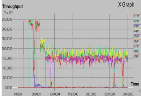
109 Figure 4: The behavior of the bandwidth occupied by
each node while the simulation
We note after the analysis of the Figure 3 that the
gateway N received a tiny quantity of packets
coming from the far nodes. However, as long as the node is near the gateway, this last receive an important quantity of packets coming from this node. To understand and define the principal cause of this result, we will try to analyze the throughput obtained by each node during the simulation.
The Figure 4 showed that the flows ofnodes near the gateway are the aggressive type, we note that they obtain a high throughput compared to the other flows, consequently, they occupy a huge part of the bandwidth at the expanse of the other.
3.
RELATED WORKSMany researchers worked on the problems affecting the WMN technology in different levels. At the level of fairness, some mechanisms had been proposed as a solution, we will present and criticize one of them, which we’ll be based on, to define our approach. Then we will place some works.
Within a node, the researchers of the work [13] tried to find the ideal combination of the queues, at the network’s and mac layer, which can guarantee a fair sharing of the bandwidth. From some simulations on several scenarios, they agreed on a system among six. The presented schema at Figure 5 explains the mechanism with the result.
[image:3.612.91.528.69.377.2]We note that the system has shown his positive effect on the fairness, it provides a queue for each flow entering the node, either at the level of the mac layer or the network layer. The service time provided by the system to the flows coming from the far nodes is shorter than the others, because these flows acquire some delays during the time they cross a node.
Figure 5: The queues system [13]
Even if the work [13] has some positive point, we will place two negative point that we will correct in our mechanism:
• The system provides a number of queues
equal to the number of flows crossing the node. However in the case of a node crossed by endless flows, this principal will be a waste of memory.
• The service time of each flow is constant
during the simulation time, it’s like we considered that the rates of each flow are constant, but it’s not the case in reality.
We will present in the following some previous works:
We start by the work [4], which was a solution to control fairly the flows in the network. The used mechanism was an inspiration from the works before it: [5] [6] [7], it’s based on three necessary parts: the first one is to limit the activation time of each antenna link. The second one is that each node has a database on the periods when each link will be active. The last one uses also the mechanism RTS/CTS to send the data.
110 This algorithm includes the advantages of two mechanisms: Shortest Path Tree (SPT) and Minimum Cost Tree (MCT).
A study was made in the article [9] on the problems whereby the WMN technology cannot guarantee a fair sharing of the bandwidth. Then, they specify the proposed mechanisms in order to decrease the consequences of this problem.
The existing work in [10] allows measuring the
available bandwidth considering the FIFO
discipline and the CSMA/CA system. The measure is based on the packets dispersion.
The authors of [11] tried to solve the congestion problem by using the 802.11e protocol, they limited the resources reservation time for each node using the TXOP parameter (transmission opportunity). For this purpose, they allocate for a node a transmission time depending on two parameter: the TXOP and the number of clients stations related to this node.
The mechanism proposed in the article [12] has as goal to solve the congestion problem using a technique of dynamic routing. This mechanism is based on an algorithm allowing the detection, firstly, the loss channel due to the congestion at the level of a node queue. Then, if a sending node data cross this canal, so they have to change trajectory to another since the WMN technology stand the fault tolerance. With this algorithm they minimized the unfairness problem.
The work [14] was executed in order to reduce the collusion probability between the flows. The concept is based on a mechanism which allows to allocate to each node a different value from CW (contention window). If we have the same CWmin and CWmax in each node, so we will have a huge probability of collusion. That’s why the mechanism chose to give the highest values of CWmin and CWmax to the nodes near the gateway and the smallest values to the far node from the gateway.
The geometric principle was present in the article [15], the authors were based on some mathematical calculations to find a geometric model that guarantees the fairness with an important number of nodes.
In the works [16][17][18][19], the authors worked on the analytic side to achieve the fairness goal, they were based on the Max-Min fairness principal.
4.
OUR APPROACHWe propose an algorithm named FGMA (fairness guarantee on medium access) so each flow in the network obtain the available gateway at an instant t. for this purpose, the mechanism guarantees to the non-aggressive flows the desired rate, however, it limits the rates of the aggressive flows to a maximal value.
To calculate the benefit rate of a flow coming from a node, we will rely on the flows rates desired by the nodes around it and desired rate by this node itself. Then, in order that the node generate a flow with its benefit rate, it must use to token bucket mechanism.
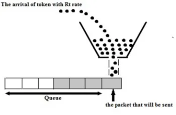
4.1 Token Bucket Algorithm
[image:4.612.335.510.354.469.2]Sometimes, a node in the network can generate a packet flow with a non-regular or high rate. In this case, we can use the token bucket mechanism to restore the rate of this flow in a constant value in a continuous way, the Figure 6 show this mechanism.
Figure 6: token bucket mechanism
The token bucket operation is as follows:
• Let’s imagine that we have a leaky bucket at
the bottom that contain some tokens and each token represents a bit.
• The size of the bucket represents the quantity
of tokens that can be stored in it, measured by bytes.
• The bucket fills with tokens with a constant
rate .
• A packet transmission is accompanied with
tokens reduction from the bucket. The number of the expelled tokens is equivalent to the packet size in bit.
• When a packet arrives and if there is not
111 the queue is congested, the packet is in excess.
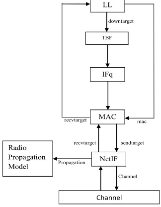
Since the FGMA protocol works in collaboration with the token bucket mechanism, this last will be integrated in the link layer of all the network’s nodes as it’s shown in Figure 7. We will affect to
each period ρ, the node benefit rate to the token
[image:5.612.108.270.214.422.2]arrival rate, in order to control the generated flow by each node with a suitable throughput.
Figure 7: The new architecture of node
4.2 The FGMA operation
The FGMA is an algorithm that runs in each
period ρ. It allows to estimate the bandwidth part
[image:5.612.90.531.225.723.2]that can reserve a node in an instant t to transmit its data. This estimation is done thanks to the calculation of the flow rate benefited by the node, based on its desired rate and the adjacent nodes desired rate.
Figure 8: The exchange of FGMA_RATE messages
The algorithm works as it follows:
• All the nodes of the network will send a
message named FGMA_RATE as a
broadcast to the adjacent nodes with a single hop.
• The FGMA_RATE contains two necessary information: the mac address of the message generator node and the desired packet rate
.
• Each node will receive many
FGMA_RATE messages, and during each reception, the node will store this message content in a table named “rate table” made of
two columns: mac address and desired rate.
The exchange of FGMA_RATE messages
is presented in Figure 8.
• At each storage of a new information in the
rate table, the node will calculate its benefit
rate from the network bandwidth.
• The node’s benefit rate will be affected
to the tokens rate .
The sum up of the FGMA mechanism is showed as it follows:
Program: This mechanism allows each node to have an accurate throughput and to guarantee the network fairness
Input:
• : all desired rate by
the adjacent nodes in a single hop at time t, and that are saved in the node x table of rates ( i • {0,1.2…,n})
• Rg : the overall rate of
the network Output:
• : the rate that will
be benefited by a node x
from the network
bandwidth at time t Begin
When we receive a FGMA_RATE message, the node performs the following actions:
• Extract from the
FGMA_RATE messages the
sender's address @ and
the rate it desired Rd.
• Save the desired rate Rd
and the sender address @ in the rates table.
• Calculate the rate that
will be benefited Rb by
the node x from the
network bandwidth.
• Affect the rate benefited
Rb to the rate of token Rt
at the token bucket
mechanism.
downtarget
mac
Propagation_
Channel sendtarget recvtarget
recvtarget LL
IFq
MAC
NetIF TBF
Channel
112
End
The mathematical formula with which we
calculate the benefit rate is a function of the
recorded values in the rate table and also some variables linked to the performance of the network. Before presenting the formula, we will define the variables that contain:
• : The rate desired by a node x at an
instant t.
• : The benefit rate of a node x at an
instant t.
• : The theoretical rate of the network.
• : The global rate of the network.
∗ ~ .
• : The evenly shared rate.
n : the number of node in the
network.
• : The residual rate.
The case when !
p :the number of nodes when
!
• " : The minimum benefit rate of a
node in the network.
The formula with which we calculate the flow
rate benefited by the node , it changes according
to the following cases:
If R$% & R'()
"
If R$% & R*
If R$% R* we will perform the following
calculation:
(1)
+ ,
, : The quantity of rate that we can add to the
node x that demands more than .
(2)
, ∗
-- : The percentage of the residual rate that will be benefited by the node x.
(3)
- . ∑1 / ∗
The formula below is applied when (
k : the number of nodes with ).
From (2) and (3):
(4)
, ∗ . /
∑ .2 /
The final formula that allows us to calculate the
benefit rate of a node x in the case of is
as follows:
From (1) and (4)
+ ∑ .∗ . /
/
1
5.
THE SIMULATION WITH FGMA5.1 Description
The importance to realize a simulation on a network with nodes, adopting the FGMA protocol, is to show that we will obtain an added value at the level of fairness, the simulation environment that we’ll choose is the same as the previous, except in this step, we will perform simulations on several topologies and scenarios in order to define the behavior of our mechanism in different cases. During the simulation, we will extract the necessary results.
113
• The Figure 9 presents the first simulation on
a bus topology of six nodes. All the network
nodes send packets to the gateway 3 .
• The second scenario shown in Figure 10 will
be on a grid topology of nine nodes (3x3), which try to send the packets to the gateway
344.
• The third scenario of the simulation
presented in Figure 11 is a random topology of nine nodes that are trying to send packets
to the gateway 3 .
• The fourth scenario is in the case when we
have a common distribution system used in order that a set of nodes send packets to different destinations. In the presented network in Figure 12 we have:
3 send packets to 35
36send packets to 34
3 send packets to 3 5
3 6 send packets to 3 4
[image:7.612.313.537.91.276.2]37 send packets to 375
Figure 9: Six nodes on a bus topology of a wireless mesh network
Figure 10: Grid topology of wireless mesh network
Figure 11: Random topology of wireless mesh network
Figure 12: Topology of stations with a common distribution system
5.2 Result
To Show that the FGMA mechanism guaranteed a fair sharing of the bandwidth, we will present to each simulation scenario the results with and without our agent.
5.2.1 bus Topology
Gateway
N0 N1 N2 N3 N4 N5
Gateway
N7
N4
N99
N2
N1
N0
N5
N3
N8
N6
N14 N9
N4
N3 N8 N13
N11 N6
N2
N1
N0
N7
N5
N12
N10
N19
N18
N16 N17
N15
N14
N13
N21 N22
[image:7.612.320.516.321.448.2][image:8.612.89.526.73.239.2]
114 Without FGMA
Figure 13: The percentage of the number of packets received by gateway from each node without FGMA
Figure 14: The behavior of the bandwidth occupied by each node while the simulation without FGMA
[image:8.612.107.274.285.422.2]With FGMA
Figure 15: The percentage of the number of packets received by gateway from each node with FGMA
Figure 16: The behavior of the bandwidth occupied by each node while the simulation withFGMA
5.2.2 Grid topology
Without FGMA
[image:8.612.292.523.297.434.2]Figure 17: The percentage of the number of packets received by gateway from each node without FGMA
Figure 18: The behavior of the bandwidth occupied by each node while the simulation without FGMA
N1
N2
N3
N4
N5
N1
N2
N3
N4
N5
N0
N1
N2
N3
N4
N5
[image:8.612.200.528.508.649.2][image:9.612.276.532.134.286.2]
115 With FGMA
[image:9.612.105.268.354.510.2]Figure 19: The percentage of the number of packets received by gateway from each node with FGMA
Figure 20: The behavior of the bandwidth occupied by each node while the simulation with FGMA
5.2.3 Random topology
[image:9.612.297.525.366.521.2]Without FGMA
Figure 21: The percentage of the number of packets received by gateway from each node without FGMA
Figure 22: The behavior of the bandwidth occupied by each node while the simulation without FGMA
With FGMA
Figure 23: The percentage of the number of packets Figure 24: The behavior of the bandwidth occupied by each
N0
N1
N2
N3
N4
N5
N6
N1
N2
N3
N4
N5
N6
N7
N8
N9
N1
N2
N3
N4
N5
N6
N7
N8
[image:9.612.107.274.564.715.2] [image:9.612.298.525.565.721.2]
116
received by gateway from each node with FGMA node while the simulation with FGMA
5.2.4 Topologie des stations avec un système de distribution commun
[image:10.612.105.288.218.374.2]Without FGMA
[image:10.612.309.544.230.385.2]Figure 25: The percentage of the number of packets received by gateway from each node without FGMA
Figure 26: The behavior of the bandwidth occupied by each node while the simulation without FGMA
With FGMA
Figure 27: The percentage of the number of packets received by gateway from each node with FGMA
Figure 28: The behavior of the bandwidth occupied by each node while the simulation with FGMA
5.3 Analyzes
The result that we have obtained has shown that our FGMA protocol took in consideration the fair sharing of the bandwidth in different simulation scenarios. The flows coming from packet generator nodes benefited from a regular rate at a continuous
time, and the bandwidths parts occupied by each flow are almost equals. We can explain this positive result this way:
At each time a packet flow crosses a node in order to reach its destination, this flow acquires a delay due to a time dispersion practiced by the
N0
N5
N10
N15
N20
N0
N5
N10
N15
[image:10.612.103.288.427.594.2] [image:10.612.310.545.447.596.2]
117 crossed node. It’s the case of the nodes flows far form the gateway, as the Figure 13, Figure 14, Figure 17, Figure 18, Figure 21 and Figure 22show, which obtain, therefore, flow rates less higher comparing to the adjacent nodes. The flows of these lasts have more chance to access to the medium, which explain the important quantity of these packets received by the gateway.
The descending packets flows of a node superior layers have always a high rate comparing to other flows coming from different nodes. For this purpose, they obtain a big opportunity to access to the queue at the expanse of the others, and consequently, the other flows packets is a time dispersion subject.
These two last findings allow sharing the flows in two categories: the aggressive flows with a high rate that obtain more chance of the medium access. Thereby, the non-aggressive flows that occupy a tiny part of the shared bandwidth.
The FGMA protocol came to limit the aggressive flows rates to not exceed a maximal rate. Consequently, these flows cannot occupy a bandwidth at the expanse of the non-aggressive flows. And also, the non-aggressive flows benefit from the bandwidth that they desire.
The conclusion is that our mechanism tried that the network’s fairness is not unbalanced, which is shown at the Figure 15, Figure 16, Figure 19, Figure 20, Figure 23 and Figure 24.
For the simulation of stations with a common distribution system, we showed that the packets flows throughputs are not regular in the Figure 25 and Figure 26. We can explain this result by the competitiveness and collusion between packets in the common medium. The FGMA tried to reduce the collusion probability by guaranteeing a non-interrupted packet stream for each flow. The Figure 27 and Figure 28 show the new results.
6.
CONCLUSIONThis work was an opportunity to study the fairness performance of WMN network, based on the 802.11s standard. From this study, we extracted some information concerning the obstacles that prevent the fair sharing of the bandwidth between the packets flows. These information were the base by which we proposed a solution.
Through the first simulation, we showed that the 802.11s standard cannot guarantee the fairness in the WMN network. The results have shown that the
aggressive flows benefit from an important part of the bandwidth comparing to the others, also the different flows throughput are not regular at the continuous time.
The results have shown also, that the flows of the far nodes from the gateway are the subject of a severe competition from the flows of nodes near the gateway, in order to reach the medium access.
The solution, to trap each flow rates in the rate interval that deserve, allows to increase the opportunity of the medium access for the non-aggressive flows, and also to guarantee the valid bandwidth for them. This method was exploited in the FGMA protocol. After the second simulation on several scenario cases, we showed its added value: it allow converging each flow throughputs to a constant and common value to reach the fairness.
REFRENCES:
[1] S.Jounaidi, Y.Saad, B.Nassereddine. “Medium Access Guarantee in Wireless Mesh Network”. International Journal of Computer Applications (0975 – 8887). Volume 112, February 2015. [2] S.Jounaidi ,B.Nassereddine, Y.Saadi, A.Haqiq.
“Bandwidth management and fairness guarantee in wireless mesh network”. International Journal
of Advanced Research in Computer
Engineering & Technology (IJARCET). August 2015.
[3] The Working Group for WLAN Standards of the IEEE. HWMP Specification [online]. Available on:
https://mentor.ieee.org/802.11/public/06/11-06-1778-01-000s-hwmp-specification.doc .
2006-11.
[4] Mohiuddin Ahmed, K.M.Arifur Rahman. “Novel Techniques for Fair Rate Control in Wireless Mesh Networks”. International Journal of Advanced Computer Science and Applications, Vol. 3, No.2, 2012.
[5] Vincenzo Mancuso, Omer Gurewitz, Ahmed Khattab and Edward W. Knightly, “Elastic Rate Limiting for Spatially Biased Wireless Mesh Networks”, ACM MobiCom (2010).
[6] Ki-Young Jang, Konstantinos Psounis, Ramesh Govindan, “Simple Yet Efficient, Transparent Airtime Allocation for TCP in Wireless Mesh Networks”,CoNEXT (2010)
[7] RANGWALA, S., JINDAL, A., JANG, K.-Y.,
PSOUNIS, K.,AND
GOVINDAN,R.“Understanding congestion
118
[8] ManaswiSaha and P. Venkata Krishna.
“Bandwidth Management Framework for
Multicasting in Wireless Mesh Networks”. International Journal of Information and Electronics Engineering, Vol. 2, No. 3, May 2012.
[9] Salitha Priyanka Undugodage and Nurul I Sarkar.
“Achieving Transmission Fairness in
Distributed Medium Access Wireless Mesh Networks: Design Challenges, Guidelines and Future Directions”, International Journal of Wireless & Mobile Networks (IJWMN) Vol. 5, No. 3, June 2013.
[10] Ajeet Kumar Singh and Jatindra Kr Deka. “A Study of Bandwidth Measurement Technique in Wireless Mesh Networks”. International Journal of Ad hoc, Sensor & Ubiquitous Computing (IJASUC) Vol.2, No.3, September 2011. [11] Jorge L S Peixoto, Marcial P Fernandez, Luis F
de Moraes. “Improving Fairness in Wireless Mesh Networks”, 29 February 2012, Saint Gilles. Reunion, The Eleventh International Conference on Networks, Pages: 175-180, 978-1-61208-183-0.
[12] Malik Mehroze, Khalid Usmani, Faraz Ahsan,
SohailAsghar. “Fairness Based Dynamic
Routing Technique (FsBDRT) in Wireless
Mesh Network”, Research Journal of
Information Technology. V5, December 2013, pages 97-103.
[13] Jangeun Jun and Mihail L. Sichitiu. “Fairness and QoS in Multihop Wireless Networks.
Available on:
http://www4.ncsu.edu/~mlsichit/Research/Publi cations/fairnessVTC.pdf.
[14] Salim Nahle, NaceurMalouch. “Fairness Enhancement in Wireless Mesh Networks”, 10-13 December 2007, Columbia University New York, 3rd International Conference on emerging Networking EXperiments and Technologies (CoNEXT) , Article No 30, 978-1-59593-770-4. [15] ane-Hwa Huang, Li-Chun Wang, and Chung-Ju Chang. “Power Fairness in A Scalable Ring-based WirelessMesh Network”, Available on: https://ir.nctu.edu.tw/bitstream/11536/6802/1/00 0257697000068.pdf.
[16] Douglas J. Leith, Qizhi Cao, Vijay G. Subramanian. « Max-min Fairness in 802.11
Mesh Networks ». Available
on:http://www.hamilton.ie/net/80211meshmax min.pdf.
[17] WenxuanGuo, and Xinming Huang. Achieving capacity fairness for wireless mesh networks. Wirel. Commun. Mob. Comput. (2009).
[18] Jian Tang, GuoliangXue, and Weiyi Zhang.
“Maximum Throughput and Fair
BandwidthAllocation in Multi-Channel
Wireless MeshNetworks”. Available
on:http://www.ics.forth.gr/mobile/Bibliography/ LoadBalancing/LB/Throughput_and_Bandwidt hAlloc_Mesh.pdf.
[19] Shweta Jain, Samir R. Das and Himanshu Gupta. “istributed Protocols for Scheduling and Rate Control to Achieve Max-Min, Fairness in Wireless Mesh Networks”. Available on:
![Figure 1: Architecture of a wireless mesh network [1]](https://thumb-us.123doks.com/thumbv2/123dok_us/8909503.958532/1.612.327.506.474.707/figure-architecture-wireless-mesh-network.webp)
![Figure 5: The queues system [13]](https://thumb-us.123doks.com/thumbv2/123dok_us/8909503.958532/3.612.91.528.69.377/figure-the-queues-system.webp)