ISSN: 1992-8645 www.jatit.org E-ISSN: 1817-3195
ELECTRIC DIFFERENTIAL WITH SVPWM DIRECT
TORQUE CONTROL USING FIVE-LEG INVERTER FOR
ELECTRIC VEHICLES
1ZULKIFILIE IBRAHIM, 2NURAZLIN MOHD YAAKOP, 3MARIZAN SULAIMAN, 4JURIFA MAT LAZI, 5AHMAD SHUKRI ABU HASIM, 6FIZATUL AINI PATAKOR.
1,3-6Faculty of Electrical Engineering, Universiti Teknikal Malaysia Melaka, 76100 Durian Tunggal,
Melaka, Malaysia
2University Kuala Lumpur, Malaysian Spanish Institute, Kulim, 09000, Kulim Hi-Tech, Kedah, Malaysia
ABSTRACT
The stability control of two separate electric vehicle (EV) motors by using only single five-leg inverter (FLI) is the motivation of this study. This paper proposes an electric differential (ED) in a FLI to serve dual separate induction motor (IM) drive-based wheels of an EV traction drive system. FLI is developed to replace the two normal three-phase voltage source inverters that need to independently control the two separate IMs at each of the EV wheels. Stability problem will be tackled by electric differential (ED) algorithm. The proposed traction drive employs space vector pulse width modulation direct torque control (SVPWM DTC) modulator with duty cycle merging algorithm as the switching sequence of the FLI. This technique allowed any portion of DC bus voltage to be allocated to any motor. Simulations were performed. The resulting control performance; speed, torque, and current verified the stability and robustness of the system. This study implies that there is possibility of using only one inverter (FLI) in order to drive two separate IM drive-based wheels without jeopardizes the system stability and robustness.
Keywords: Electric Vehicle (EV), Five-Leg Inverter (FLI), Electric Differential (ED), Dual Motor.
1. INTRODUCTION
Recently, two wheels motors traction drives have received an increasing interest in electric vehicle (EV) control systems due to the challenge of having the best stability performance by discovering the ability of the inverters to control the dual separate traction motors [1-4]. Current distribution control of dual directly driven wheel motors has been studied by [1], while [2-3] proposed an adaptive electric differential to the dual wheels drive for electric vehicle motion stabilization. K. Hartani et. all, [4] used the behavior model control as the vehicle stability enhancement control for electric vehicle with dual motors drive and A. Nasri et. all, [5] used sliding mode control. Many efforts were devoted to the study of multi-motor multi-converters systems (MMS) which many have used two normal three-phase inverters to independently control these two motors as shown in figure 1. The stability and robustness of the system is well performed with
ISSN: 1992-8645 www.jatit.org E-ISSN: 1817-3195
unwind dual motors centre-driven using five-leg inverter [7].
The chronological of reducing the MMS was started with the multi-motors sharing the DC bus, but each of it has its own VSI, the advantage of not having extra rectifier than to reduce the cost. Later, some of the researchers introduce new circuit topology of having less switches 4 leg and 9 switches [8]. Hence, the cost and complexity can also be reduces. In 2000, Gataric et. all, [9] investigated a method shown that, by connecting five-phase stator windings in series in an appropriate manner, it becomes possible to control independently dual motors with the supply coming from a single five-phase VSI. That latter enabled of having only one inverter to control the dual motors independently. As for traction motor for electric vehicle application, there are also attempts done to reduce the number of inverters to control multi-motors by reducing the components; i.e. reduce the switch count [10] from 6 to 4, but the motor use only two-phase power supply, the third leg is connected to both motor by capacitors. While in [11] only introduce the idea of having FLI to control the dual motors in EV and just that, no findings had been reported to date. In this paper, ED will be introduced in FLI traction drive system to independently control the stability of EV.
EC
ES
VSI
IM IM
Rear wheels Front wheels
[image:2.612.349.482.85.214.2]VSI
Figure 1. Dual Inverters To Supply Dual Motors EV Traction Drive Configuration (IM: Induction Motor, VSI: Voltage Source Inverter (Normal Three-Phase) As Power Converter, ES: Energy
Storage, ECU: Electronic Controller Unit).
EC
ES
FLI
IM IM
[image:2.612.137.253.450.553.2]Rear wheels Front wheels
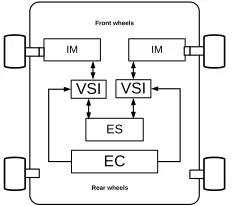
Figure 2. Proposed EV Traction Drive With Five-Leg Inverter Fed Two Separate Induction Motors Configuration (IM: Induction Motor, FLI:
Five-Leg Inverter As Power Converter, ES: Energy Storage, ECU: Electronic Controller Unit).
ISSN: 1992-8645 www.jatit.org E-ISSN: 1817-3195
2. ELECTRIC VEHICLE DUAL-MOTOR
SINGLE INVERTER CONFIGURATION
There are several possible EV drive line configurations [17]. Motor-drive integrated driving mode was the choice for the proposed FLI. The reason is that the motor of this kind driving mode can perform integrated driving axis transmission system with dual motors. It removed the gears and totally realized by electronics controlled. The advantages of this driving mode are; it has compact transmission, high transmission efficiency and easy installation. The ED is connected to the front wheels as depicted in figure 2.
3. CONTROL OF THE FIVE-LEG
INVERTER ELECTRIC VEHICLE DUAL-MOTOR TRACTION DRIVE
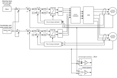
The proposed FLI EV dual-motor traction drive control system is as shown in figure 3. In this system, the EV front wheels are associated with ED. The left and right wheels are directly connected to each of the induction motors. The dual-motor are fed by only one inverter, which is the five-leg inverter and controlled by a SVPWM DTC strategy.
PI PI
PI Snych
ro
Stationar y
SVM
*
r
ω
r
ω
*
Te
*
s
λ v*d
*
q
v
Flux & torque estimator
VSI
3 PHASE INDUCTION MOTOR
S
v
S i
PI PI
PI Snych
ro
Stationar y
SVM
*
r
ω
r
ω
*
Te
*
s
λ v*d
*
q
v
Flux & torque estimator
3 PHASE INDUCTION
MOTOR
S
v
S
i
6 to 5 modulator
1/ 2 +
-−
-right ω
left
ω
Left and right cornering =
1/ 2 +
-−
-right ω
left
ω
Vehicle Speed=V Speed order
V
w
∆
w
∆ +
+
+
-+
-+
-+
+
-+
-+
-Steering input left and right
cornering
[image:3.612.102.512.289.563.2]Accelerator and brake pedal input
Figure 3. Proposed EV five-leg inverter fed two separate induction motor control system schematic diagram.
3.1. Stability Control
Speed or torque is the main performance criteria that will show the stability condition of an EV, during straight path and while cornering. The two different wheels will have different speed reference during cornering regime and should maintain the synchronous speed during straight path regime. The easiest method to design ED is the one proposed by Guillermo A. Magallan [19]. It is known as “equal torque
ISSN: 1992-8645 www.jatit.org E-ISSN: 1817-3195
linear speed or total velocity (v) is maintained constant during each maneuver. Therefore, by selecting the desired speed of the vehicle, the DTC torque commands are produced. Each IM rotation speed depends on the selected driving regime type; straight-line regime, the turning regime, and wheel slip-page, where one of the motor experiences almost zero load torque [2 and 14,]. For the straight-path regime, the motor rotation speeds are
ωl=ωr=𝑣r (1)
For the second regime, cornering regime as shown in figure 4 below, the rotation speeds for each motor are different. For example, in the right turning way, these speeds are expressed as
⎩ ⎪ ⎪ ⎨ ⎪ ⎪
⎧ωl= 2v
�1 +ρρ −+ 2d2d�r= v
r +∆ω
ωr= 2v
�1 +ρρ −+ dd�r= v
r− ∆ω
∆ω= dρvr
(2)
where ∆ω is the speed different between inner wheel and outer wheel. As example right turning, the right wheel is the inner wheel while the left wheel is the outer wheel.
B IM
IM A
Center of Turn
r L
V1
2d
y
C
p
Vr
V
[image:4.612.333.530.357.514.2]X
Figure 4. Electric vehicle driving trajectory model
3.2. Five-Leg Inverter Circuit Topology
Five-leg two-motor drive structure offers a saving of two switches when compared with the
standard dual three phase voltage source inverter (VSI) [24 -27]. Thus, it offers a reduction in the inverter structure complexity and also it enable control of two three-phase motors with only one DSP. This advantage can be utilized in the dual traction motors of an EV and there is possibility of reducing the drivelines structure complexity and devices. Figure 5 shows the main structure of the FLI. The idea of having possible FLI independent control of two motors was first introduced by [23]. The FLI serves two three-phase IMs. Both motors need three inputs, as the results the C leg works as a common leg. Leg A1 and B1 are connected to phase U and V of motor one (M1), while leg A2 and B2 are connected to phase U and phase V of motor 2 (M2) respectively. Switching functions Si (i=1, 2, 3, 4, 5) are defined as Si = 1 when the upper switch is on and Si = 0 when it is off. There are a total of
32 switching states (25) in a five-leg VSI,
available for control of the two motors [8].
Figure 5. Main Circuit Topology Of Two Three-Phase IM Fed By Five-Leg Inverter.
The maximum voltage value at terminal of an open switch is always equal to the DC voltage
VDC (i.e. at rated value such that full operating
[image:4.612.93.273.498.658.2]ISSN: 1992-8645 www.jatit.org E-ISSN: 1817-3195
𝑉𝑈𝐹% =√23𝑎𝑚𝑎𝑥100 (3)
3.3. SVPWM-DTC
Field oriented control and DTC are the two most popular advanced control methods to control the performance of an IM. DTC has simple structure and fast torque response advantages [28]. DTC with space vector modulation (SVM) scheme is proposed in order to improve the classical hysteresis DTC. Paper [12] reported that compared with the steady-state performance of lookup table DTC and SVPWM-DTC, the latter produces much lower torque ripple. This is results from the injection of zero-vector instead of backward active zero-vectors to reduce torque. Another advantage of SVPWM-DTC is it operates at a constant switching frequency.
The behaviour of induction motor in DTC drives principal can be described in terms of space vectors by the following equations written in the stator stationary reference frame:
𝑣𝑠=𝑟𝑠𝑖𝑠+𝑑𝜑𝑑𝑡𝑠 (4)
0 =𝑟𝑟𝑖𝑠− 𝑗𝜔𝑟𝜑𝑟+𝑑𝜑𝑟𝑑𝑡 (5)
𝜑𝑠=𝐿𝑠𝑖𝑠+𝐿𝑚𝑖𝑟 (6)
𝜑𝑟=𝐿𝑟𝑖𝑟+𝐿𝑚𝑖𝑠 (7) 𝑇𝑒=32𝑃|𝜑𝑠||𝑖𝑠| sin𝛿
(8)
Where P is the number of pole pairs, 𝜔𝑟 is the
rotor electric angular speed in rad/s, Ls, Lr and Lm
are the motor inductances, rs is the stator
resistance, [ohm] Ω and 𝛿 is the angle between
the stator flux linkage and the stator current
space vectors. Based on (1) the ds- and qs- axis
stator flux in the stationary reference frame can be written as:
𝜑𝑠,𝑑𝑠=��𝑣𝑠,𝑑𝑠− 𝑖𝑠,𝑑𝑠𝑟𝑠�𝑑𝑡 (9)
𝜑𝑠,𝑞𝑠=��𝑣𝑠,𝑞𝑠− 𝑖𝑠,𝑞𝑠𝑟𝑠�𝑑𝑡 (10)
In terms of switching states Sa, Sb, and Sc (which
can either be 0 or 1) the voltage vectors in (7) are given by:
𝑣𝑠,𝑑𝑠=13𝑉𝑑𝑐(2𝑆𝑎− 𝑆𝑏− 𝑆𝑐) (11)
𝑣𝑠,𝑞𝑠= 1
√3𝑉𝑑𝑐(𝑆𝑏− 𝑆𝑐)
(12)
The electromagnetic torque given in (6) can be
written in the ds – qs coordinates as:
𝑇𝑒=32𝑃�𝜑𝑠,𝑑𝑠𝑖𝑠,𝑞𝑠− 𝜑𝑠,𝑞𝑠𝑖𝑠,𝑑𝑠� (13)
[image:5.612.331.517.262.395.2]The two similar types of three phase induction motors are used in the simulation studies and details about the motor parameters are shown in table 1 below.
Table 1: Induction Motors Parameters
Stator resistance, Rs 7.83Ω
Rotor resistance, Rr 7.55Ω
Stator self inductance, Ls 0.4751H
Rotor self inductance, Lr 0.4751H
Mutual inductance, Lm 0.4535H
Number of poles, p 4
Stator flux rated 0.954
Torque rated 13 Nm
Power 1.5 kW
Speed 1460rpm
[image:5.612.90.233.406.499.2]ISSN: 1992-8645 www.jatit.org E-ISSN: 1817-3195
32 available inverter switching states are utilized. For further understanding, figure 6 shows the block diagram of SVPWM-DTC with PI controllers of one IM drive.
PI PI
PI Snychro
Stationary
SVM
*
r
ω
r
ω
*
Te
*
s
λ *
d
v
*
q
v
Flux & torque estimator
VSI
3 PHASE INDUCTION
MOTOR
S v
[image:6.612.95.290.163.251.2]S i
Figure 6. Block diagram of SVPWM-DTC three-phase IM drive.
The basic principle of SVPWM algorithm is it has eight voltage vectors. There are six base vectors has same amplitude and two zero vectors (000) and (111). As shown in figure 7, in the first
sector adjacent to the two voltage vector U1 and
U2 as well as the zero vector can synthesis
reference vector Uref in accordance with the
method of voltage-second balance.
U1T1+ U2T2+ U0T0= UrefTS (14)
where T1 and T2 are the duration time of active
vectors, T0 is the duration time of zero vectors
and Ts is the PWM cycle. From these, the duty
cycle of the active vectors and zero vectors are determined.
Figure 7. Voltage Vectors And Sectors.
Consider a SV approach to the inverter modeling. Similar principles to those explained in the case of carrier-based PWM [1] of the FLI apply when one considers the SVPWM method for two-motor drive. The existence of zero-sequence signal injection makes it possible for the FLI being able to independently control two three-phase IMs. It is well known that the
zero-sequence signal represents a degree of freedom that is normally used to improve the DC bus utilization and reduce harmonic current losses of the carrier-based method [8]. The zero-sequence signal does not appear in either line-to-line or phase voltages of the three-phase motor. This offer a possibility to utilize the principle of zero-sequence signal injection in a very different manner for a five-leg two-motor drive. Voltage references for each motor are vectors situated in any of the six sectors in their d-q plane of stationary reference frame (as in DTC schemes). Assuming that both modulators are in continuous modulation where total time of application of zero SVs is equally shared among zero SVs 000 and 111, and also the remaining time is determined on average over the switching period of the two adjacent active SV. The three-phase SVPWM modulators will generated the duty
cycle values δ over the switching period ts (time
‘ON’ over the total switching period) for each of the three legs. A simple summing of the duty cycles generated can be used to determine the resulting five duty cycles for the FLI. That is,
δA1= δa1+ δc2 δB1= δb1+ δc2 δC= δc1+ δc2
δA2= δa2+ δc1 δB2= δb2+ δc1
(15)
The values of duty cycles calculated by each three-phase SV modulator are in the range
(0:1), where the switching period ts is equal to 1
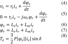
[image:6.612.119.262.499.607.2]p.u. Then as in normal SV zero space vector 111 should be injected in the middle of the switching pattern, generated duty cycles will have values equal to 0.5 when the input reference is zero. After summation defined with (5), the FLI duty cycles get shifted into the range (0.5:1.5), which is not applicable with the value of the witching period. Due to this the value from the resulting duty cycles calculated using (15) must continuously subtracted by 0.5. This is shown in figure 8 where the principle of SVPWM for a FLI supplying a two-motor drive is illustrated [8]. The net effect of the duty cycle summation is the redistribution of the application times of the zero SVs. From the first three equations of (15), it is visible that the addition of the value of the
duty cycle δc2 increases all three duty cycles,
ISSN: 1992-8645 www.jatit.org E-ISSN: 1817-3195
000 is decreased (before shifting by – 0.5), without affecting the application times of the two active SVs. The same explanations apply to M2 on the basis of the last three equations of (15). After the application of the SVPWM principle, these sequences and application time durations of active SVs for M1 and M2 stay preserved in the final five duty cycles of the five-leg VSI. It can be further seen that the distribution of the application times for zero vectors 000 and 111 for each of the two machines is different in FLI compared with in M1 and M2, whereas the total zero vector application time (sum of 000 and 111 application times) is kept the same. It is also noticeable that there are instants within the switching period when both machines simultaneously receive their active SVs (overlapped parts, for example, vector 11001 of the five-leg VSI, which corresponds to the active vectors 110 and 010 of the two machines,
respectively, since inverter legs A2 and B2 supply
phases a and b of the second machine while
phases c are paralleled to the inverter leg C1,2).
Thus the individual SV references of each machine are complementary and the modulator is able to simultaneously satisfy the needs of both motors. It is also visible that in the remaining instants the individual SV references of each machine are conflicting and so the needs of one machine are met, whereas the second machine receives zero SV (111 or 000). What this means
is that all 25=32 switching states of a five-leg
VSI are utilised and there are no restrictions regarding the use of any of them. The resulting PWM pattern is symmetrical with two commutations per inverter leg and is thus easy to implement using standard DSP PWM units.
Figure 8. The principal of an improved SVPWM for FLI: the combination of two standard three-phase
SVPWM performed five duty cycles signals.
4. SIMULATION RESULTS AND
ANALYSIS
The simulations of the proposed ED for FLI with using SVPWM merging duty cycle technique have been done using MATLAB/Simulink. The two IM rated parameter are given in Table 1. Base on the vehicle reference speed profiles [2], two situations of ED performance have been evaluated: 1) the straight path regime, where the two motor have synchronous speed, and 2) the cornering regime, where each motor have different speeds as shown in figure 9 below. The outer wheel moves slower than the inner wheel if the EV needs to perform a cornering regime. As additional we also test the reversed operation of the two wheel motors. These results can literately be compared to works done in [2] and [17], but [17] was using permanent magnet synchronous motors.
Speed (rpm)
Stop
Start
Phase 1 Phase 2 Phase 3
[image:7.612.330.511.354.448.2]Time (sec)
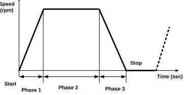
Figure 9. EV speed reference: Phase 1: ramp-up, speed increases linearly, phase 2: constant speed and
phase 3: ramp-down, speed decreases linearly.
[image:7.612.95.291.534.634.2]ISSN: 1992-8645 www.jatit.org E-ISSN: 1817-3195
(a)
(b)
[image:8.612.78.533.56.729.2](c)
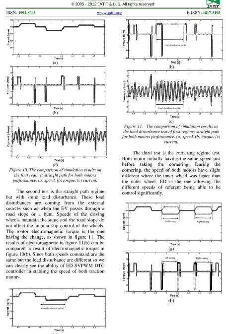
Figure 10. The comparison of simulation results on the first regime: straight path for both motors performance. (a) speed. (b) torque. (c) current.
The second test is the straight path regime but with some load disturbance. These load disturbances are coming from the external sources such as when the EV passes through a road slope or a bum. Speeds of the driving wheels maintain the same and the road slope do not affect the angular slip control of the wheels. The motor electromagnetic torque is the one having the change, as shown in figure 11. The results of electromagnetic in figure 11(b) can be compared to result of electromagnetic torque in figure 10(b). Since both speeds command are the same but the load disturbance are different so we can clearly see the ability of ED SVPWM DTC controller in stabling the speed of both traction motors.
(a)
(b)
[image:8.612.92.306.72.398.2](c)
Figure 11. The comparison of simulation results on the load disturbance test of first regime: straight path for both motors performance. (a) speed. (b) torque. (c)
current.
The third test is the cornering regime test. Both motor initially having the same speed just before taking the cornering. During the cornering, the speed of both motors have slight different where the inner wheel was faster than the outer wheel. ED is the one allowing the different speeds of referent being able to be control significantly.
(a)
(b)
0.4 0.6 0.8 1 1.2 1.4 1.6 1.8 2 0 100 200 300 400 500 Time (s) S pe e d (r pm )
0.4 0.6 0.8 1 1.2 1.4 1.6 1.8 2 -15 -10 -5 0 5 10 15 Time (s) T or que ( N m )
0.4 0.6 0.8 1 1.2 1.4 1.6 1.8 2
-8 -6 -4 -2 0 2 4 6 8 Time (s) C ur r e nt ( A m p)
0.4 0.6 0.8 1 1.2 1.4 1.6 1.8 2 0 100 200 300 400 500 Time (s) S pe e d (r pm )
Load disturbance applied
0.4 0.6 0.8 1 1.2 1.4 1.6 1.8 2 -15 -10 -5 0 5 10 Time (s) T or que ( N m )
Load disturbance applied
0.4 0.6 0.8 1 1.2 1.4 1.6 1.8 2
-8 -6 -4 -2 0 2 4 6 8 Time (s) C ur r e nt ( A m p)
Load disturbance applied
0.4 0.6 0.8 1 1.2 1.4 1.6 1.8 2 0 100 200 300 400 500 Time (s) S pe e d (r pm ) Right turning Left turning
[image:8.612.92.523.449.735.2]ISSN: 1992-8645 www.jatit.org E-ISSN: 1817-3195
(c)
Figure 12. The comparison of simulation results on the second regime: cornering for both motors performance. (a) speed. (b) torque. (c) current.
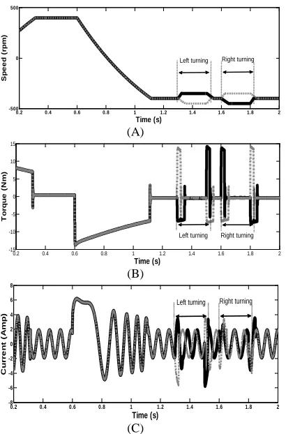
The last test done was forward and reversed action plus during the reversed period cornering is applied to the motors. As shown in figure 13 below, the motor ramp up to 400 rpm then at t=0.6s the speed command change to -400 rpm, which make the motors to turn direction. After it reach steady state, the left and right turning regime were applied to both of the motor. The torque and current performance can be seen in figure 13(b) and (c).
(A)
(B)
(C)
Figure 13. The Comparison Of Simulation Results On The Forward Reversed Operation: Straight Path
And Cornering During Reversed For Both Motors Performance. (A) Speed. (B) Torque. (C) Current.
5. CONCLUSION
The focus of this study is the ED performance in FLI SVPWM DTC to control dual motor drive-based wheels of an EV traction drive system. FLI SVPWM DTC with single drive is able to maintain the stability and robustness of an EV. FLI reduced the number of inverter and power supply needed to control two traction motors of an EV. Even though, only with single drive the two motors can be control independently at any speed and at any torque simultaneously. The system is capable of maintaining the stability and robustness of both motors during straight path and cornering regime with or without load disturbance by controlling the delta speed and current also the ability of the merging duty cycle SVPWM technique for FLI to allocate any portion of DC bus to any motors following the demand.
REFERENCES
[1] Y. P. Yang, and C. P. Lo, "Current
distribution control of dual directly driven wheel motors for electric vehicles," Control Engineering Practice, vol. 16, pp. 1285-1292, 2008.
[2] B. Tabbache, A. Kheloui, and M. E. H.
Benbouzid, “An adaptive electrical differential for electric vehicles motion
stabilization,” IEEE Trans. Veh.
Technol.,vol. 60, no. 1, pp 104-110, Jan. 2011.
[3] K. Hartani, M. Bourahla, Y. Miloud, and M.
Sekour, "Electronic differential with direct torque fuzzy control for vehicle propulsion system," Turk J Elec Eng & Comp Sci, vol. 17, pp. 21-38, 2009.
[4] K. Hartani, and Y. Miloud, “Vehicle
stability enhancement control for electric vehicle using behavior model control,” in book “Electric Vehicles - Modelling and Simulations" edited by Seref Soylu, ISBN 978-953-307-477-1: InTech, September 9, 2011, ch. 6, pp. 127-158.
[5] A. Nasri, A. Hazzab, I. K. Bousserhane, S.
Hadjeri, and P. Sicard, “Fuzzy-sliding mode speed control for two wheels electric vehicle
drive,” Journal of Elect. Eng. And Technol.
(Tubitak), vol. 4, no. 4, pp 499-509, 2009
[6] A. Emadi, Y. J. Lee, and K. Rajashekara,
“Power Electronics and Motor Drives in Electric, Hybrid Electric, and Plug-In
0.4 0.6 0.8 1 1.2 1.4 1.6 1.8 2
-8 -6 -4 -2 0 2 4 6 8
Time (s)
C
ur
r
e
nt
(
A
m
p)
Left turning Right turning
0.2 0.4 0.6 0.8 1 1.2 1.4 1.6 1.8 2 -500
0 500
Time (s)
S
pe
e
d
(r
pm
)
Left turning Right turning
0.2 0.4 0.6 0.8 1 1.2 1.4 1.6 1.8 2
-15 -10 -5 0 5 10 15
Time (s)
T
or
que
(
N
m
)
Left turning Right turning
0.2 0.4 0.6 0.8 1 1.2 1.4 1.6 1.8 2
-8 -6 -4 -2 0 2 4 6 8
Time (s)
C
ur
r
e
nt
(
A
m
p)
[image:9.612.92.297.367.678.2]ISSN: 1992-8645 www.jatit.org E-ISSN: 1817-3195
Hybrid Electric Vehicles,” IEEE Trans. Ind. Electron., vol. 55, no. 6, Jun. 2008
[7] M. Jones, D. Dujic, E. Levi, M. Bebic, and
B. Jeftenic, “A two motor centre-driven winder fed by a five-leg voltage source inverter,” Proc. European Power Electronics and Applications Conf. EPE, Aalborg, Denmark, 2007, CD-ROM paper 83
[8] M. Jones,S. N. Vukosavic, D. Dujic, E.
Levi, and P. Wright, "Five-leg inverter PWM technique for reduced switch count two-motor constant power applications," Electric Power Applications, IET, vol. 2, pp. 275-287, 2008.
[9] S. Gataric, "A polyphase Cartesian vector
approach to control of polyphase AC machines," 2000, pp. 1648-1654 vol. 3.
[10]E. Ledezma, B. M. Grath, and A. Munoz,
"Dual AC-drive system with a reduced switch count,", IEEE Transactions on Industry Applications, vol. 37, pp. 1325-1333, 2001.
[11]M. Jain, and S. Williamson, "Modeling and
analysis of a 5-leg inverter for an electric vehicle in-wheel motor drive," IEEE Canadian Conf. Elect. and Comp. Eng. (CCECE), pp. 1-5, 2010.
[12]S. Lu, and K. Corzine, "Direct torque
control of five-phase induction motor using space vector modulation with harmonics elimination and optimal switching sequence," IEEE Applied Power Elect. Conf. and Exp., pp 195-201, 2006.
[13]N. Mohd Yaakop, Z. Ibrahim, M. Sulaiman
and M.H.N. Talib, “Speed Performance of SVPWM Direct Torque Control for Five Leg Inverter Served Dual Three-Phase Induction Motor”, IEEE Int. Power Eng. and Opt. Conf. (PEOCO), pp 323-328, 2012.
[14]M.H.N. Talib, Z. Ibrahim, N. Abdul Rahim,
and N. Mohd Yaakop, “Development of Combined Vector and Direct Torque Control Methods for Independent Two Induction Motor Drives”, IEEE Int. Power Eng. and Opt. Conf. (PEOCO), pp 78-83, 2012.
[15]R. Rajamani, Vehicle Dynamics and
Control. Mechanical Engineering
Series, New York: Springer, 2006, ch. 1, pp. 8.
[16]J. D. Santiago, H. Bernhoff, B. Ekergard, S.
Eriksson, S. Ferhatovic, R. Waters, and M. Leijon, “Electrical motor drivelines in commercial all-electrical vehicles: a
review,” IEEE Trans. Veh. Technol., vol. 61, no. 2, Feb. 2012
[17]G. Li, W. Hong, D. Zhang, and C. Zhong,
“Research on control strategy of two independent rear wheels drive electric
vehicle,” Physics Procedia, vol. 24, pp.
87-93, 2012.
[18]E. Ledezma, B. McGrath, A. Muñoz, and T.
A. Lipo, “Dual AC-Drive System with a Reduced Switch Count,” IEEE Trans. Ind. Appl., vol. 37, no. 5, pp 1325-1333, Sept./Oct. 2001
[19]C. Fu, R. Hoseinnezhad, Simon Watkins,
and Reza Jazar, “Direct Torque Control for Electronic Differential in an Electric Racing Car” School of Aerospace, Mechanical and Manufacturing Engineering, RMIT University, Victoria 3083, Australia
[20]M. H. Westbrook, “The Electric and Hybrid
Electric Car”. The Institution of Electrical Engineers, pp. 44-47, 2001.
[21]K. Hartani, M. Bourahla, Y. Miloud, and M.
Sekour, "Electronic differential with direct torque fuzzy control for vehicle propulsion system," Turk J Elec Eng & Comp Sci, vol. 17, pp. 21-38, 2009.
[22]G. A. Magallan, C. H. D. Angelo, and G. O.
Garcia, "Maximization of the Traction Forces in a 2WD Electric Vehicle," IEEE Transactions on Vehicular Technology, pp. 1-1, 2011.
[23]Ph. Delarue, A. Bouscayrol, B. Francois,
“Control implementation of a five-leg voltage-source-inverter supplying two three-phase induction machines,” Proc. IEEE Int. Elec. Mach. and Drives Conf. IEMDC, Madison, USA, 2003, pp. 1909–1915.
[24]Y.Kimura, M.Hizume, K.Oka, and
K.Matsuse, "Independent Vector Control of Two Induction Motors with Five-Leg Inverter by the Expanded Two Arm PWM
Method", The 2005 International Power
Electronics Conference, pp.613-616, 2005.
[25]K.Oka, Y.Ohama, H.Kubota, I.Miki, and
K.Matsuse: "Characteristic of Independent Two AC Motor Drives Fed by a Five-Leg Inverter ", 2009 IEEE Industry Applications Society Annual Meeting, CD-ROM.
[26]E. Levi, M. Jones, S.N. Vukosavic, A. Iqbal,
ISSN: 1992-8645 www.jatit.org E-ISSN: 1817-3195
[27]J. M. Lazi, Z. Ibrahim, and M. Sulaiman,
“Mean and diffrential torque control using hysteresis current controller for dual PMSM drives,” Journal of Theoretical and Applied Information Technology, Vol. 33, ( 1), , pp. 76-82 Nov. 2011
[28]A. Jidin, N. R. N. Idris, A. H. M. Yatim, T.
Sutikno, and M. E. Elbuluk, "Extending switching frequency for torque ripple reduction utilizing a constant frequency torque controller in DTC of induction motors," Journal of Power Electronics, vol. 11, pp. 148-155, 2011.
[29]K. Oka, Y. Nozawa, and K. Matsuse, "An
improved method of voltage utility factor for
PWM control of a five‐leg inverter in two
induction motor drives," IEEJ Transactions on Electrical and Electronic Engineering, vol. 1, pp. 108-111, 2006.
[30]A. Dixit, N. Mishra, S. K. Sinha, and P.
Singh, "A review on different PWM techniques for five leg voltage source inverter," IEEE Int. Conf. On Adv. In Eng., Sc. and Management, ICAESM 2012, pp. 421-428.
[31]M.Hizume, S.Yokomizo, and K.Matsuse,
"Independent Vector Control of Parallel-Connected Two Induction Motors by a Five- Leg Inverter", 10th European Conference on Power Electronics and Applications, CDROM, paper 778, 2003.
[32]M. Jones, D. Dujic, E. Levi, "A Performance
Comparison of PWM Techniques for Five-Leg VSls Supplying Two Motor Drives", IECON- 2008, The 34nd Annual Conference of the IEEE Industrial Electronics Society, pp.508-513, CD-ROM, 2008.
[33]B. Francois, A. Bouscayrol: ‘Design and

![figure 8 where the principle of SVPWM for a FLI supplying a two-motor drive is illustrated [8]](https://thumb-us.123doks.com/thumbv2/123dok_us/8917275.962439/6.612.119.262.499.607/figure-principle-svpwm-fli-supplying-motor-drive-illustrated.webp)