Tribology in Industry
www.tribology.rsSimulation of Anti Wear Performance Using a
Modified Brugger Test Set Up
J. Sequard-Base
a,b, A. Grafl
c, U. Cihak-Bayr
a, F. Franek
aa AC2T research GmbH, Viktor Kaplan Straße 2/C, 2700 Wr. Neustadt, Austria, b Ballistix Academy e.U., Rittschein 19, 8362 Übersbach, Austria,
c Lukoil Lubricants Europe GmbH, Uferstraße 8, 1220 Wien, Austria.
Keywords:
Hydraulic oils Pump test Brugger test
Anti-wear performance Oil pre selection
A B S T R A C T
Modern hydraulic oils have to fulfill a broad variety of parameters limitations to guarantee a proper system performance throughout a considerable lifetime. A comprehensive test of the liquids nowadays just can be performed by using long term hydraulic pump test set ups, including several different test stages.
One of the most critical parameters in hydraulic pump testing is the pump wear indicating the anti-wear performance of the used oil. In this paper the authors focused on the development of a new testing procedure based on a simple standardized Brugger test aiming to achieve similar wear results as in a Parker Denison T6H20C pump test set up.
The test conditions of a standard Brugger test are changed by taking a brass cylinder, reducing the normal load to 1 kg, increasing the test duration to 300 seconds, providing a well-defined surface roughness by using a 2,500 x grinding paper and perform 4 repetition tests to obtain a statistical more reliable measurement value.
By using the new method it was possible to get a pre selection between pass and fail oils according to the wear properties without the necessity of performing an elaborated pump test.
The preselection of hydraulic oils according to their anti-wear properties offers a huge cost saving potential for hydraulic oil developments.
© 2018 Published by Faculty of Engineering
Corresponding author:
J. Sequard-Base
Ballistix Academy e.U., Rittschein 19, 8362 Übersbach, Austria.
E-mail: [email protected]
1. INTRODUCTION
Hydraulic systems have gained a huge variety of applications in different industry sectors. Their great advantage is that the power generation (pump) can be placed in a distance to the region where a specific force has to act (hydraulic cylinder). Beside the force transfer, the hydraulic oil has also to protect the
hydraulic systems from damage occurring in a high pressure, high temperature and sometimes corrosive environment. All parts of the system are subjected to these conditions but the most critical one is the hydraulic pump [1]. In the last century the development of hydraulic pumps lead to three principle types: piston, gear and vane pumps.
R
ES
EA
R
The test method described here is developed to simulate wear in a piston pump. The basic working principles of these pumps are depicted in Fig. 1. A swashplate axial piston pump has a rotating cylinder containing several pistons. A spring pushes the piston against the stationary swashplate, which is mounted at an angle to the cylinder. The pistons suck the fluid during half a revolution and push the fluid out during the other half. Piston pumps can work at pressures beyond 40 MPa and operate at a normal fluid viscosity range of 10 to 160 cSt.
Fig. 1. Drawing and scheme of piston pumps [3].
Essential part of the hydraulic system is the hydraulic fluid. Hydraulic fluid manufacturers are facing an ever increasing challenge to produce fluids with improved tribological properties and produce energy-efficient outcomes. One method of evaluating the lubricating abilities of these fluids is to test them in the hydraulic pump of interest. However, similar to hydraulic oils’ variety, a wide range of different operating conditions and contact material exist in different hydraulic pump types. It is practically impossible and tedious to qualify hydraulic fluids by testing in the whole range of different pumps available. This problem, to some extent, is handled by conducting one or few identified standard hydraulic pump tests and laboratory-based tribological tests. Furthermore, since the interaction of additives, tribofilm formation and AW (anti-wear) performance would differ significantly based on the materials in tribological contact, it is important to use contact pair materials similar to those used in actual hydraulic pump of interest.
The focus was explicitly not put onto an in depth investigation of the wear process itself. A study on the film forming process in tribologically stressed surfaces for various anti-wear additives in hydraulic fluids was already performed earlier [2]. Target of this paper was the development of a new testing procedure based on a simple standardized Brugger test aiming to achieve similar wear results as in a Parker Denison T6H20C pump test set up by modifying the normal loads, test durations and specimen materials.
2. STATE OF THE ART
The performance of hydraulic oils in various application regimes is commonly quantified in standardised pump tests. One example to which is referred in accordance to the oil rankings presented in this paper is the Parker Denison T6H20C pump test which uses a combination of a vane - and a piston pump. The test is divided in 2 stages of 300 h operation time each. In the first stage the oil is tested under dry, elevated temperature conditions of 110 °C and pump outlet pressures between 25 and 28 MPa on the vane and piston pump, respectively. The second stage is run for another 300 h with a water contamination of 1 % in the oil. For achieving a pass result for the pump test the visual inspection of the main pump parts must not show signs of abnormal wear; the fluid has to have satisfactory filterability results and the maximum weight loss is 300 mg for all 9 pistons and 15 mg for the vanes and pins [4].
The sophisticated procedure of a pump test in general, as described for the Parker Denison test, is quite expensive and time-consuming. For oil development a quick, simplified test done on a standardised bench test to predict if oils would pass a pump test related to anti wear performance would be a beneficial tool.
Following are the widely used standards for studying the tribological properties of hydraulic fluids:
wear results obtained by pump tests with various hydraulic fluids. However, intensive studies on the correlation of wear of a broad range of hydraulic fluids tested according to ASTM D 2741-68 and wear obtained at various critical points in a gear, piston and vane pump allowed some conclusions: Load carrying capacity must not be the dominating factor to the hydraulic pump AW performance, an AW test seems favourable. Accelerated tests often provide no correlation. Material pairs for the bench tests must be the same as the mating pair of the tribocontact in the hydraulic pump. It is necessary to evaluate hydraulic fluids over a wide range of test conditions, loads, speeds, material pairs and, where necessary, contact geometry. A single set of test conditions appears usually to be inadequate [5].
An extensive study focused on nanocoatings for high efficiency industrial and tooling systems by ORNL investigated two different lubricants on tribometers, various lab-scale tests with parts of original pump parts and in pumps (Eaton). The results were consistent in many cases of different coatings. However, the relative friction and wear behaviour of different fluids was not in sufficient consistency [6].
Fig. 2. Setup of the test bench simulating the piston-bore interface from [6].
Experiments with Shell 4-ball tester and FZG are shown in [7], however no correlation to pump behaviour is provided. An effective bench test for hydraulic fluid selection was searched for in [8] by applying most commonly used bench-type wear tests. These are listed in Table 1. The Timken block on ring test offers a simple specimen geometry but with the lack that edge running effects of the block can never be excluded. The authors conclude, that the test should be as simple as possible, provide controlled fluid circulation and specimen configuration close to this in the actual pump. Furthermore it has to be done at a wide range of loads and speed.
Table 1. Common wear tests used in [8].
Type of
machine Type of friction Media Remarks
Shell (four-ball) E.P.
ASTM-2783 Sliding
Stationary balls –
rotating ball Assess the load-wear index and weld point under severe conditions.
Shell (four-ball) Wear
ASTM-2266 Sliding
Stationary balls – rotating ball
Assess the anti-wear properties of test sample and wear scar of ball under light load condition.
Falex wear properties test
ASTM D-2670 Sliding
Stationary V-blocks – rotating
journal
Assess the wear properties of fluid by the number of ratchet-type mechanism to keep constant load over a fixed test time Falex E.P.
properties test
ASTM D-3323 Sliding
Stationary V-blocks – rotating
journal
Assess the load-carrying properties of fluid by increasing the load.
Timken E.P. test ASTM-
2782 Sliding
Stationary block – rotating cup
Assess the load-carrying capacity of lubricants by determining the minimum load at which scoring or seizure occurs and the maximum load where it cannot occur
Several papers evaluating the tribological performance of potential hydraulic fluids and components thereof use 4-ball tester, reciprocating ball-on-flat tests like Optimol ® SRV 4 or FZG test rig [9-15]. They all provide interesting results of e.g. wear mechanisms or tribofilm formation, however, none provides indications for connection of the results to real pump performance.
A ring on block test machine was used in [16]. The wear results of 6 hydraulic fluids were compared to vane, gear and piston pump test results. Load-carrying capacity shows no correlation to the performance according to anti wear behaviour of fluids. Accelerated tests tend to produce wrong results concerning correlation to pump tests. Furthermore, materials for the test pieces must be similar to those of the actual machine. If the conditions of the pump cannot be reproduced sufficiently, the testing conditions should be more widespread. In general, the researches came to the conclusion, that it is not possible to get information on wear characteristics from friction results. However, the finally proposed correlation for a vane pump is valid just for comparing completely different fluids and shows bad reproducibility.
Europe, is not enough to characterise hydraulic fluids according to wear.
In [18] a test set up like in the Brugger method is used to differentiate between synthetic and mineral base oil components in engine oils according to wear scar diameter.
In [19] it was possible to rank gear oils according to API performance level by using a Brugger test set up in combination with a four-ball apparatus. However, the Brugger results are supposed to give better results to differentiate between the performance levels.
Concluding, a simple tribometrical procedure to predict wear behaviour in piston pumps does not exist.
3. OILS
For the present study 9 oils were investigated. They are listed in Table 2, where Oil1 – Oil 7 are fully formulated hydraulic oils and tested in a Denison pump.
Table 2. Data of investigated oils.
Sample KV 40
KV 100 VI
Elemental composition [mg/kg]
[m²/s *10-6] P S Zn Ca
Oil1 43.5 7.9 160 570 950 <5 <5 Oil2 48.5 8.6 160 210 3,500 <5 <5 Oil3/Batch1 47.6 8.6 161 410 1,200 <5 100 Oil3/Batch2 44.9 8.3 0 490 1,200 <5 180 Oil4 46.6 8.5 162 150 230 <5 <5 Oil5 46.5 9.1 182 770 320 <5 10 Oil6 46.7 9.2 185 210 880 <5 <5 Oil7 46.0 8.1 149 330 700 450 60 BO 46.5 6.8 99 <5 1,300 <5 <5 BO+AW 46.7 6.8 99 410 2,100 480 <5 KV40 – kinematic viscosity at 40 °C, KV100 – kinematic viscosity at 100 °C, VI – viscosity index, P – phosphorus, S – sulphur, Zn – zinc, Ca – calcium.
Fig. 3. Denison pump test results for Oil1-Oil7.
The results of the pump tests according to piston mass loss are depicted in Fig. 3. BO and BO+AW are mineral oils type base oil and the same including an aliphatic ZDDP anti-wear additive. These samples were used in the development of the test method.
4. METHOD DESCRIPTION
The Brugger test set up is commonly used for the quantification of extreme pressure performance of lubricants. The test apparatus and procedure are defined in DIN 51347-1. The apparatus consists of a fixed steel cylinder and a steel ring crossed at an angle of 90° according to their symmetry axes. The stationary top cylinder (diameter 18 mm) is pressed via a system of two coupled levers against the bottom circular ring with 25 mm diameter. The rear lever is loaded with 2.45 kg of dead weight resulting in a contact force between the crossed cylinders of (400 ± 10) N equivalent to an initial maximal Hertzian contact pressure of (2.26 ± 0.02) GPa at the standard specimens. Before contacting the two cylinders, the lubricant is poured over the ring. Subsequently the front lever, on which the static cylinder is mounted, is lowered leading to a contact between the cylinders. Then the rear lever is loaded with the dead weight. 60 s after pouring the oil on the ring the test is started. The ring rotates at 960 rpm, equivalent to a sliding speed of 1.2 m/s. After another 30 s the test is stopped. An elliptical wear scar is formed on the static cylinder. The dimensions of the long a and short b axes of the wear scar are the basis of Brugger wear quantification. According to the DIN 51347-1 the so called “Belastbarkeit nach Brugger”, further called Brugger number B is defined as normal force F per nominal contact area at the end of the experiment and can formally be written in the following way:
(1)
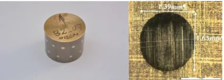
A typical test cylinder with several wear marks on its surface can be seen in Fig. 4.
For evaluating the wear scar dimensions an optical incident light microscope with 5–10x magnification is used.
4.1 Wear in steel/steel contact following the standard procedure
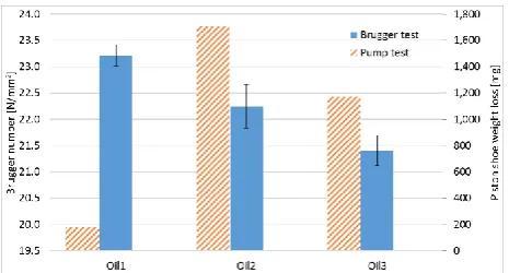
Brugger tests according to DIN51347-1 and DIN51347-2 were performed with the pump tested oils Oil1, Oil2 and Oil3 and are compared to the piston shoe weight loss data of Denison pump tests. The results are depicted in Fig. 5. Error bars for the Brugger test indicate the standard deviation of the test results.
Fig. 5. Comparison between standard Brugger tests with tribological interaction between a steel ring and a steel cylinder characterised by the Brugger number and pump test results where the weight loss of the brass piston shoes sliding against a steel swashplate is measured.
The difference in Brugger number between a “pass” oil (Oil1) and “fail” oils (Oil2 and Oil3) is low. Furthermore, the relative oil ranking in Brugger test is not representing the pump test results. These results lead to the assumption that the contact conditions (e. g., type of contact, contacting materials, contact pressure, temperature, dominant wear mechanism, regime of lubrication) in pump tests cannot be simulated using the standard Brugger tests.
Concluding, the cylinder specimen was replaced by different brass materials which is described in the following sections to reproduce the wear results from the pump tests between the brass piston shoe and the steel swash plate.
4.2 Investigated brass alloys
The first intention to modify the standard Brugger test set up was in changing the cylinder material. Therefore samples made of two different brass alloys were compared to the
original piston shoe material. Brass2 made by Wieland under the brand name SB7 and Denison Brass produced by Caro Prometa under the brand name CW713R (DIN 2.0550). The microstructures of the three alloys are shown in Table 3.
Table 3. Microstructure of the brass used in piston shoes of hydraulic pump tests, SB7 and CW713R for 3 different magnifications in light microscope.
In all investigated materials three different phases typical for brass are present: the Cu matrix α-phase, which appears dark yellow in the light microscopy image of the etched cross section, the Zn rich β-phase, which appears bright yellow and quite evenly distributed, small precipitations coloured in grey. The precipitations in the material SB7 are much finer grained compared to the ones in CW713R and the alloy used in the piston shoe component. These two alloys also show differences in the microstructure as the piston shoe material exhibits a pronounced bimodal size distribution of the precipitation, also showing some agglomerations, whereas the distribution of the hard precipitations in CW713R is much more even, but the grains are larger and have a hexagonal shape.
SEM-EDX measurements (shown in Table 4 and Table 5) revealed that the investigated alloys contain completely different precipitations. The precipitations in the piston shoe alloy contain Al, Fe, Co, Ni and small amounts of Si, whereas the ones in grades SB7 and CW713R can clearly be recognized as SiMn-precipitations, which are typical for brass. The main difference between SB7 and CW713R is the high Ni content in the SB7 precipitations.
material, a lower one for CW713R and SB7 is lacking any Al.
The mechanical properties hardness and Youngs modulus, measured by nano-indentation, are shown in Table 6. The two brass alloys do not differentiate much from each other. However, a clear difference in hardness and Youngs modulus between grains and matrix can be seen for both materials.
Table 4. Chemical composition of the investigated brass alloys in weight %. The values are averaged over α- and β-phases.
Brass Material Cu Zn Al
Piston Shoe 62 34 4
CW713R 63 35 2
SB7 62 38 -
Table 1. Chemical composition of the precipitations in the investigated brass alloys in weight%.
Brass Material Al Si Mn Fe Co Ni
Piston shoe 16 9 - 15 18 42
CW713R - 26 69 5 - -
SB7 - 21 36 - - 43
Table 2. Mechanical properties of the investigated brass samples.
Brass Material Hardness [GPa] E [GPa]
Matrix Grains Matrix Grains
CW713R 3.5±0.4 11±2 125±8 151±33
SB7 3.0±0.3 10±2 120±6 165±13
Neither of the two alloy grades SB7 and CW713R match the alloy used for the piston shoe component. In terms of chemical composition SB7 is closer, but the microstructure of CW713R has more similarities to the piston shoe material.
4.3 Impact of normal load on wear
The intention of the test was to get a quantitative ranking in the anti-wear performance between several hydraulic oils. So the most important aim was to achieve a differentiation between oils which show different wear performance in pump tests. In a first step, the applied normal load on the lever was varied in the range of 1 – 4 kg dead weight which corresponds to initial maximum contact pressures between 1.5 – 2.2 GPa, respectively. Loads below 1 kg, especially a completely unloaded lever result in increased vibrations of
the lever due to unavoidable minimal runout of the rotating cylinder. In Fig. 6 the wear results of load variations are depicted.
Fig. 6. Wear area for different loadings and Oils 5, 6 and 7. All Brugger tests were performed under following conditions: 2,500 polishing paper, 30 s, CW713R.
All oils show an increase in the wear scar area with increasing load, but the differentiability strongly decreases for higher loads. Concluding, the further tests were conducted with 1 kg normal load.
4.4 Impact of test duration on wear
Brugger tests according to DIN 51347 are performed for 30 s, which normally leads to wear marks in the range between 6 and 20 mm². When using brass cylinders the reduced Young´s modulus of the contact pair is much smaller which results in a lower initial contact pressure.
Oils with good anti-wear performance can reduce wear especially during the constant wear regime. For an increased relative time span in steady state conditions the contact conditions have to be as stable as possible. In a Brugger test this is equivalent to an increase of the test duration.
Figure 7 illustrates the nominal contact pressure evolution in dependence on the contact area. There is clearly a steep pressure decrease until approximately 0.5 mm² is reached. This is near the wear scar area of pass oils (e.g. Oil5 in Fig. 6) in Brugger tests using Brass as cylinder material.
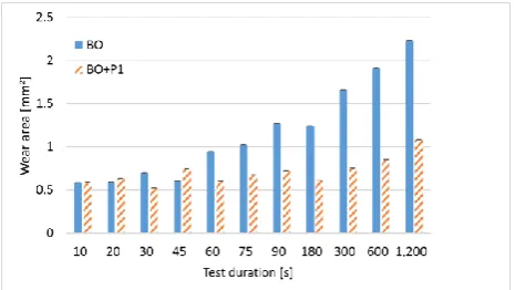
Fig. 8. Wear area over test duration for modified Brugger tests for BO and BO+P1. All tests were performed under following conditions: 2,500× polishing paper, 1 kg equivalent to an initial contact pressure of 1.5 GPa, SB7.
Furthermore, longer test durations should result in less impact of random influence factors at the beginning of the test. Therefore, they should show a higher differentiability between the oils. The results of test durations between 10 and 1,200 s for the oils BO and BO+P1 are depicted in Fig. 8. They show that the additive package of P1 lead to a nearly constant wear from 10 s to 5 min of test duration. Testing longer than 5 min increases wear for P1. In contrast to this behaviour BO already shows an increased wear area after 45 s of test duration. Taking into account the measurement spread there is an optimum combining differentiability of the tested model oils and total test duration (including cooling times between the tests) between 90 s and 300 s.
4.5 Impact of brass grade on wear
Brugger tests using both brass alloys were performed and correlated with piston pump weight loss results for pass and fail oils. The results are depicted in Fig. 9. Brugger tests using CW713R show no differentiability between the “pass oils” 1 and 4 and the “fail oils” 2 and 3. Tests using SB7 show significantly lower wear for the “pass oils” 1 and 4 than for the “fail oils” 2 and 3. Therefore SB7 was used in most of the following experiments.
Fig. 9. Brugger test results of various pump tested oils for the brass alloys CW713R and SB7 with the indication of pass or fail result in Parker Denison pump test. All tests were performed under following conditions: 2,500x polishing paper, 90 s, initial contact pressure of 1.5 GPa.
The results show that slight changes of the grain structure and material composition shown in 4.2 can have crucial impact on the forming of a wear reducing layer if a suited oil like oil 1 is used.
4.6 Impact of counter body (ring) roughness
on wear
The effect of roughness of the counter body (ring) on wear area of SB7 cylinders is depicted in Fig. 10. Polishing papers with different abrasive grain sizes (500x to 4,000x) were used to prepare different roughness.
Fig. 10. Comparison of different ring surface modification treatments using various polishing papers in modified Brugger tests done for 4 consequent ring grinding procedures.
All tests were performed under following conditions: oils BO and BO+P1, 90 s, initial contact pressure of 1.5 GPa, SB7.
there is nearly no differentiation between the oils. Best relative differentiability was found for the 2,500x polishing paper.
4.7 Modified Brugger test procedure –
correlation with pump test wear
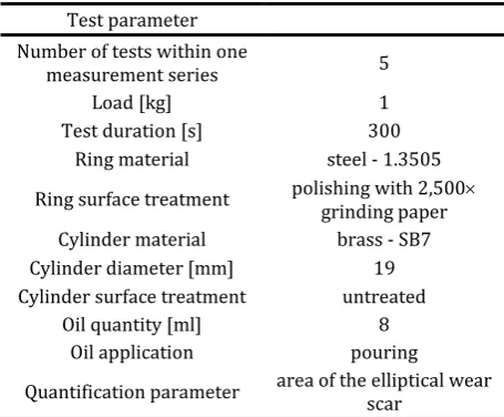
The adaptations on the Brugger test procedure described above, led to a parameter set-up which showed good reproducibility between the single tests as well as a good differentiability between various pump tested oils. In Table 7 the optimised test parameters are listed. Using this parameters the results depicted in Fig. 11 were achieved using brass SB7. Error bars represent the standard deviations of 5 single test results. It has to be mentioned that for Oil3 a different batch was tested in the Brugger apparatus than in pump test. Clearly the qualitative trends gained from Brugger tests match very well with results from pump tests. The dashed green line indicates the limit of wear for the pump test of 300 mg for all piston shoes. Oil 6 and 7 are “pass oils” at the pump test. They show also wear scar areas below 0.9 mm² in the modified Brugger. Oil 1 and 4 also pass the pump test in terms of wear. In modified Brugger test they show lower wear than all investigated “fail oils”. However, the differences in wear scar area to oils 3 and 5 on the border of significance. Oil 2, which show high wear at pump test, also produces the relatively highest wear in modified Brugger test.
Table 7. Selected test conditions for modified Brugger test set up on SB7.
Test parameter Number of tests within one
measurement series 5
Load [kg] 1
Test duration [s] 300
Ring material steel - 1.3505
Ring surface treatment polishing with 2,500grinding paper
Cylinder material brass - SB7
Cylinder diameter [mm] 19
Cylinder surface treatment untreated
Oil quantity [ml] 8
Oil application pouring
Quantification parameter area of the elliptical wear scar
A regression between the piston weight loss data from pump tests and the wear scar area of the modified Brugger tests is depicted in Fig. 12.
A fair correlation is provided. The only deviation from the regression can be seen for oil 3, where the model test was performed with a different oil patch in comparison to the pump test. The logarithmic correlation is the best experimental fit to depict the nonlinear relationship between the volume of the piston weight loss and the Brugger wear area. The intact trend gives an indication that the wear process taking place in the modified Brugger test set up is comparable to the operation conditions in the pump test.
Fig. 11. Results of modified Brugger tests with SB7 in comparison with weight loss data from hydraulic pump tests.
Fig. 12. Correlation between hydraulic pump tests and modified Brugger tests with SB7.
Summarized the conclusion can be drawn, that modified Brugger tests using SB7 instead of the steel cylinder at test durations of 300 s are capable to give a first and quick estimation of the oil ranking in hydraulic pump tests. However, validation of this correlation will need additional experiments, in detail more pump tested “fail” oils would be necessary.
5. CONCLUSIONS
methods which aim to predict the result of a pump test, but cannot provide a sufficient correlation to distinguish between small variations in the oil composition. In the current work a simple test set up was developed based on the Brugger test machine. In contrast to other model tribotests it exhibits a good correlation to standard pump tests and therefore enables an oil ranking prior to time and cost intensive pump tests. The main findings are:
• Modified Brugger tests are using brass SB7 cylinder instead of steel and operate with reduced normal pressure in the tribocontact for a total test duration of 300 seconds. • Modified Brugger tests react sensitive on
the surface condition of the steel ring (much harder material than the brass cylinder) and on the used brass grade. Best results are achieved using a 2,500 x grinding paper. • In order to get a reliable measurement
result each test should be repeated four times.
• By following the modified Brugger test conditions it is possible to reproduce the oil ranking of the pump tests. A value for the elliptical wear scar area of 0.95 mm² can be taken as threshold between a pass and a fail oil in a respective piston pump test.
Acknowledgement
This work was funded by the Austrian COMET Programme (Project K2 XTribology. No. 849109) and carried out at the ‘‘Excellence Centre of Tribology’’. The authors wish to thank Evonik Industries AG Oil Additives, Lukoil Lubricants Europe GmbH and voestalpine Stahl GmbH for their financial support and active research cooperation. The authors would also like to thank Norbert Nagy of AC2T research GmbH, Austria for conducting some Brugger experiments.
REFERENCES
[1] T. Hong, R.K. Tessmann, Computerized Design Analysis of Machine Tool Hydraulic System Dynamics, FES/BarDyne Technology Transfer Publication #11, pp. 1-14, 1998.
[2] B. Vengudusamy, A. Grafl, F. Novotny-Farkas, T. Schimmel, K. Adam, Tribological behaviour of
antiwear additives used in hydraulic applications: Synergistic or antagonistic with other surface-active additives? Tribology International, vol. 67, pp. 199-210, 2013, doi: 10.1016/j.triboint.2013.07.016 [3] Hydraulic training - Axial piston units: Basic
principles, Rexroth Bosch, RE 90600/01.98 http://www.insanehydraulics.com/library/files /Hydraulic-Trainings-for-Axial-Piston-Units.pdf, accessed: 01.09.2018.
[4] G.E. Totten, V.J. De Negri, Handbook of hydraulic fluid technology, CRC Press Inc, 2006.
[5] G.E. Totten, G.H. Kling, D.J. Smolenski, Tribology of hydraulic pump testing, Philadelphia: ASTM 1997. [6] P. Blau, J. Qu, C. Higdon, Nanocoatings for high
efficiency industrial and tooling systems, CRADA Final Report, 2011, doi: 10.2172/1005178 [7] Houghton Offshore Report, Cosmolubric B-series,
Biodegradable and fire resistant hydraulic fluids https://de.scribd.com/document/202099981/Hou ghton-Cosmolubric-B-Series, accessed: 01.09.2018. [8] R.K. Tessmann, T. Hong, An effective bench test
for hydraulic fluid selection, in SAE Off-road Machinery Conference, 13-15 September, 1993, Milwaukee, Wisconsin, US, paper 932438. [9] J. Wang, J. Wang, C. Li, G. Zhao, X. Wang,
Tribological performance of poly (sodium 4-styrenesulphonate) as additive in water-glycol hydraulic fluid, Lubrication Science, vol. 24, iss. 3, pp. 140-154, 2012, doi: 10.1002/ls.1169 [10] S. Plaza, L. Margielewski, G. Celichowski, R.W.
Wesolowski, R. Stanecka, Tribological performance of some polyoxyethylene dithiophosphate derivatives water solutions, Wear, vol. 249, iss. 12, pp. 1077-1089, 2001, doi: 10.1016/S0043-1648(01)00847-X
[11] G. Mendoza, A. Igartua, B. Fernandez-Diaz, F. Urquiola, S. Vivanco, R. Arguizoniz, Vegetable oils as hydraulic fluids for agricultural applications, Grasas Aceites, vol. 62, no. 1, pp. 29-38, 2011, doi: 10.3989/gya.056210
[12] J. Wang,J. Wang, C. Li, G. Zhao, X. Wang, A high-performance multifunctional lubricant additive for water-glycol hydraulic fluid, Tribology Letters vol. 43, iss. 2, pp. 235-245, 2011, doi: 10.1007/s11249-011-9799-1
[13] H. Camenzind, D. Clark, A. Dratva, M. Fletschinger, M. Ribeaud, P. Rohrbach, J. Reyes-Gavilan, New ashless, hydrolytically stable and FZG active antiwear agent, Tribology Transactions, vol. 45, iss. 2, pp. 223-231, 2002, doi: 10.1080/10402000208982544
tribofilms generated by highly efficient, friction-reducing additive in water-polyglycol-glycol lubricant, Lubrication Science, vol. 21, pp. 297-304, 2009, doi: 10.1002/ls.91
[15] Z. Longhua, Study of a novel anti‐wear additive used in ashless anti‐wear hydraulic fluid, Industrial Lubrication and Tribology, vol. 61, iss. 5, pp. 271-276, 2009, doi: 10.1108/00368790910976104 [16] K. Mizuhara, Y. Tsuya, Investigation of a method
for evaluating fire-resistant hydraulic fluids by means of an oil testing machine, Tribology International, vol. 25, iss. 1, pp. 37-43, 1992, doi: 10.1016/0301-679X(92)90119-8
[17] H. Olsson, J. Ukonsaari, Wear testing and specification of hydraulic fluid in industrial
applications, Tribology International, vol. 36, iss. 11, pp. 835-841, 2003, doi: 10.1016/S0301-679X(03)00101-4
[18] P. Thapliyal, G.D. Thakre, Correlation Study of Physicochemical, Rheological, and Tribological Parameters of Engine Oils, Advances in Tribology, vol. 2017, article ID 1257607, 2017, doi: 10.1155/2017/1257607
![Fig. 1. Drawing and scheme of piston pumps [3].](https://thumb-us.123doks.com/thumbv2/123dok_us/9804355.1966390/2.595.59.284.236.444/fig-drawing-scheme-piston-pumps.webp)
![Table 1. Common wear tests used in [8].](https://thumb-us.123doks.com/thumbv2/123dok_us/9804355.1966390/3.595.56.286.443.536/table-common-wear-tests-used.webp)