Cite this article as: Karam, Z. A., Awad, O. A. "Design of Active Fractional PID Controller Based on Whale's Optimization Algorithm for Stabilizing a Quarter Vehicle Suspension System", Periodica Polytechnica Electrical Engineering and Computer Science, 2020. https://doi.org/10.3311/PPee.14904
Design of Active Fractional PID Controller Based on Whale's
Optimization Algorithm for Stabilizing a Quarter Vehicle
Suspension System
Zeyad Abdulwahid Karam1*, Osama A. Awad1
1 Systems Engineering Department, College of Information Engineering, Al-Nahrain University, P. O. B. 64046, 64074 Baghdad, Iraq * Corresponding author, e-mail: [email protected]
Received: 28 August 2019, Accepted: 18 December 2019, Published online: 24 February 2020
Abstract
Improving the dynamic performance of an automobile suspension system is considered as the main demand for comfortable and safe passenger travelling. From all previously proposed and implemented works, it is noticed that there are other factors that need to be
considered to raising the car holding and stability in the road for improved passenger comfort when travelling. The minimization of car
body displacement and oscillation time after exposure to road disturbances have been adopted in this work due to their contribution in raising the car holding and stability. The improvement in these features was maintained via a robust control methodology.
The Fractional Order PID controller tuned by the Whales Optimization Algorithm (WOA) and Particle Swarm Optimization (PSO) algorithm is suggested in this work as a robust controller to reduce the effect of these demerits. In this paper, an active quarter car
suspension nonlinear system is designed for the presented goals using a robust controller. Minimizing the displacement of the car
body and reducing the damping frequency are achieved via a nonlinear control strategy using the fractional order PID controller, which can maintain the required characteristics. Tuning the parameters of the FOPID controller is performed by using the Whales Optimization Algorithm (WOA). Robustness of the FOPID controller is examined and proved to withstand a system parameter variation
of ±12 % in all system parameters and a maximum of ±80 % in controller parameter variation. Simulation outcomes also indicate
a considerably improved performance of the active suspension system with the fractional order PID controller over the traditional PID.
Keywords
quarter car suspension system, FOPID controller, PSO algorithm, WOA algorithm
1 Introduction
In the last decade, the development of car systems takes a large scope and interest according to the relation of the active trade cars market. Suspension systems are regarded as the most important factor in vehicle design, which is highly related to passenger comfort and car sta-bility. As an essential part of the vehicle's body, a quar-ter suspension system is attached to each wheel. It is assembled from four parts: a tyre, a spring, a linkage, and a damper as a shock absorber. The design of an old suspen-sion system is composed of a spring, damper, and mass, also known as a passive suspension system. Many car manufacturers designed the suspension system with
spe-cific control stability criteria to raise passenger com -fort and ride stability. The designed systems can handle the minimum range of road peaks (road bumps) and pits;
with these ranges, the car body will be subjected to oscil-lations after this road disturbance that results in an uncom-fortable travel and unstable ride.
The active car suspension system was proposed by many manufacturers to handle these passive suspension draw-backs. The active system of hydraulic actuator with a pis-ton rod between the car body and some points of
suspen-sion system structure to overcome the car body deflection
(oscillation) after exposing to different disturbances that are related to road postures. One of the main issues associated with active car suspension systems is the need for a robust control strategy that can control the hydraulic actuator to achieve optimal controlled suspension system character-istics with the presence of model uncertainty, some param-eter variations, and/or inaccurate feedback measurements.
Many works in the past decade were accomplished in order to design, model, and control the active suspen-sion system. Kumar, attempted to develop an active car suspension system using the traditional PID control to achieve improved dynamic characteristics in suspension
system deflection. Controller tuning was conducted using
the Zeigler and Nichols method [1].
Two creative works were accomplished in 2010, the first
one proposed by Aldair and Wang [2], where a full vehicle nonlinear active suspension system was modelled and con-trolled by a Fractional Order PID (FOPID). The controller was designed, and parameters were optimized using Genetic
Algorithm (GA). The outcome manifested the efficiency of
the suggested controller. The second study was presented by Pekgökgöz et al. [3], in which a fuzzy logic controller was examined to control an active car suspension system of a quarter model. The Genetic Algorithm was applied to opti-mize the membership function distribution within the uni-verse of discourse of the fuzzy controller. The proposed Fuzzy PID controller provided performance over the PID
controller for minimizing the ultimate body deflection.
Nagarkar et al. [4], presented good analyses to passive and active suspension systems, controlled by utilizing the Linear Quadratic Regulator (LQR) approach. The LQR controller displayed a better achievement for compartment riding in comparison to the passive suspension system.
In 2012 another two remarkable studies were per-formed by Mouleeswaran [5], where the active suspension system improvement was achieved by considering the fre-quency analysis for the rode disturbances imposed on the system. The tests showed the applicability of the PID con-trol as an active mechanism. The second study was
pro-posed by Goga and Kľúčik [6], where a mathematical
model for the half-car suspension system was developed. The passive suspension system parameters were opti-mized by the GA. The outcome showed the improvement of inactive system performance.
Aly and Salem [7] modelled an automatic quarter car
suspension system controlled using fuzzy controller FLC
to improve vehicle stability for any road disturbance that interrupts the ride. The drawn conclusion showed that
FLC is more efficient than the classical approach.
An adaptive control strategy was used to track the rode disturbances while keeping the car driving stability. The proposed adaptive controllers considered a novel strategy for controlling nonlinear models presented by Sun et al. [8, 9].
In 2013, Yao et al. [10] proposed a combined model ref-erence control system with sliding mode control that was designed to be easily implemented. The determination of the sliding mode control is achieved so that the error dynamics between the reference model and the plant states were asymptotically stable.
Two studies for controlling the active suspension system,
using the H∞ method, reported on the design robust
control-lers minimizing the control stability criteria to maintain the stable ride and comfort proposed by Guo et al. [11], and by Wang et al. [12]. Ozer et al. [13] proposed an optimized
Sliding Mode Controller (SMC) tuned by using the Genetic
Algorithm for a half suspension vehicle model. The proposed
SMC improves ride passenger comfort and car stability.
Drehmer et al. [14] determined the parameters of the suspension system for a frequency domain
vehi-cle model subjected to diversified road profiles such that
a multi-objective function is minimized. The programming of sequential quadratic and Particle Swarm Optimization algorithms are utilized to establish the optimal parameters of a suspension system in accordance with various
veloc-ity situations and road profiles.
The control strategy of an additive actuator was proposed by Dong et al. [15], where a combined nonlinear model of a quarter car suspension system and actuator of electro-hy-draulic type was implemented. The FOPID control was designed and implemented to manipulate the displacement of the actuator. The results showed that FOPID controller parameters performed better than the PID controller.
Deshpande et al. [16] proposed an active suspension sys
-tem that satisfies the objectives of both an improved com
-fort in riding and, at the same time, keeping the deflection
in suspension system bounded by the boundary of the rat-tle space. The proposed approach relied on a new
nonlin-ear disturbance compensator for the suspension deflection. A creative work is proposed by Concilio et al. [17].
Here they developed a variable geometry car suspension system which was designed to be simple in construction, small in size, requires minimum energy for its implemen-tation, and can be installed without substantial changes
to the original passive suspension system through retrofit -ting operations. The device was applied to a vehicle com-puter-aided design model.
Another good work is initiated by Fu et al. [18], where a quarter car active suspension system is designed by an optimal adaptive control approach. The Approximate Dynamic Programming algorithm (ADP) is applied.
The proposed methodology presented an improved per-formance when exposing to unknown road displacement.
Xue et al. [19] proposed a suspension system using
Finite-Time Stability (FTS) control combined with H-infinity con
-troller. The stability of input-output finite-time to the bound
of H∞ with an appropriate term that guarantees the mixture of
IO-FTS/H∞ behavior for a linearized system was presented.
The proposed control strategy was proved via simulation. From all the works that were proposed and imple-mented in the past, it is noticed that there are other factors that need to be considered for raising the car holding and stability in the road with passengers travelling comfort. The minimum car body displacement and minimum oscil-lation time after exposing to road disturbances (cusp or holes) have a contribution in raising the car holding and stability. These extra active suspension system character-istics can be achieved by using a robust control method-ology to satisfy the required characteristics. The FOPID controller tuned by Particle Swarm Optimization (PSO) and the Whales Optimization Algorithm (WOA) is sug-gested in this work and showed to produce an optimized controller that maintains these characteristics.
The remaining sections of this article are arranged as follows: in Section 2, the mathematical model and the Simulink modelling of the nonlinear active car suspen-sion system are detailed. In Section 3, the FOPID controller is presented. The hybrid PID and FOPID controllers tuned by Particle Swarm Optimization (PSO) are designed and tested in Section 4. In Section 5, PID and FOPID controllers tuned by the Whales Optimization Algorithm (WOA) are designed and simulated. The system modelling is
imple-mented by MATLAB Simulink. In Section 6, the simu -lation results of each controller are displayed. Section 7 summarizes the percentage of enhancement in system per-formances compared to previously tackled works. Finally, the robustness tests for the proposed controllers are dis-cussed and conclude in Sections 8 and 9 respectively.
2 Model and simulation of the active quarter car suspension system
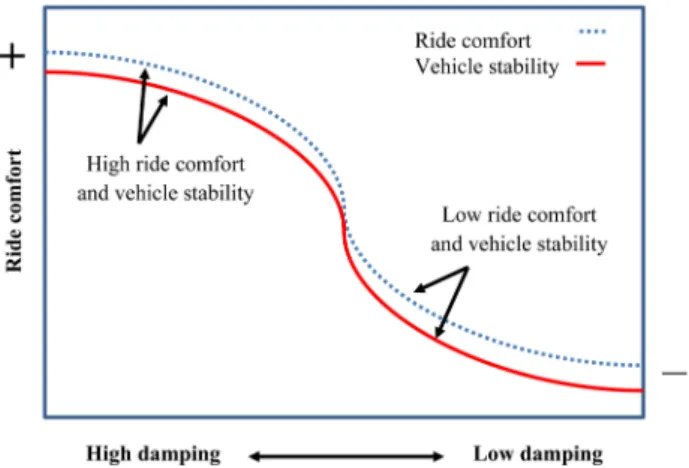
The traditional engineering system for dissipating car wheel disturbance is designed by involving two elements, a spring and a damper. These two parts are combined into structuring passive suspension systems. The design of the suspension system provides a compromise between the stability of the vehicle and the ride comfort.
Fig. 1 summarizes this relation when ride comfort increases at low damping with vehicle stability and vice versa at high damping. The car suspension system is
developed based on two conflicting objectives of passive
springs and dampers. Therefore, many models have been designed and tested to improve the car holding and stabil-ity in the road.
The design of the active suspension system includes the insertion of a hydraulic-servo actuator that can be con-trolled electrically by a controllable servo valve. The inserted actuator is structured by connecting it between the body of the car and the wheel mass. The actuator then performs the control on the displacement between the body and
the wheel as the last is deflected due to road disturbances.
The acceleration of system masses is measured by sensors, then feeding it back as analogue signals to the controller. The controller will take the optimum action to leverage
the efficiency of the system by dissipating the cusp actions
through stroke retract or the holes action through stroke
extrusion. The controlled signal is amplified and fed to the
actuator, such that the required force is generated between the car body and the wheel mass. Fig. 2 illustrates the sche-matic representation of the closed-loop active car suspension system [5] and [7]. The active suspension system is dynam-ically represented by the following Eqs. (1) and (2) [5, 7]:
m Xss+K Xs
(
s−Xus)
+C Xa(
s−Xus)
−ua=0 (1) m X K X X C X X K X Z u us us s us s a us s t us rt a +(
−)
+(
− )
+(
−)
+ =0. (2)The parameters of a quarter active suspension system with respect to the static equilibrium position, as given by [5, 7] are shown in Table 1.
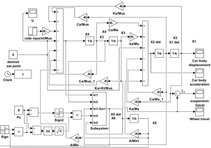
Fig. 3 shows the Simulink model of a quarter active car suspension system.
The state-space representation of Eqs. (1) and (2) becomes:
X1=X2, (3)
X m K X X C X X Am X s s a s 2 1 3 2 4 5 1 = −
(
−)
+(
−)
+ , (4) X3=X4, (5) X m K X X C X X K X Z A m X us s a t rt s 4 1 3 2 4 3 5 1 = − (
−)
+(
−)
+(
−)
+ , (6) X =βX5+A X(
2−X4)
+X6ω, (7) X X t U = 6 , (8) ω =sgnP −sgn( )
X ∗X P−sgn( )
X ∗X , s 6 5 s 6 5 (9) where X1=X Xs, 2=X Xs, 3=X Xus, 4=X Xus, 5 is thepressure inside the chamber of hydraulic piston and X6 is
the valve displacement.
3 FOPID controller
In 1999, Podlubny [20] introduced the concept of the FOPID controller. The primary difference between a PID and FOPID controller is that the order of integral and derivative in the FOPID is non-integer. This enhancement led to the generation of a nonlinear PID controller. By depending on this attribute, the extra degrees of freedom in obtaining the tuned parameters leads to the utmost dynamic perfor-mance of the FOPID in comparison to the conventional PID controller as presented by Tepljakov et al. [21] and by Taher et al. [22]. The control of fractional order is considered the core in modelling fractional-order systems. The operator of non-integer-order is fundamentally given by:
aD d dt d Z t a t α α α α α α τ α α = > ( ) = ( ) < ∈ −
∫
0 1 0 0 , , ; , (10)where t and a represent the operation boundaries.
The α refers to traditional integration or differentiation.
Many definitions work out for the generalized operator. Tepljakov et al. [23] provides the following definition:
α α τ τ τ α α D f t m d dt f t d t m m a t ( ) = − ( ) ( ) − ( ) − +
∫
1 1 Γ , (11)where Γ ⋅( ) represent the Euler's gamma function for
m− < <1 α m m N, ∈ . Also the Grunwald–Letnikov rep-resentation is considered due to its importance for a numer-ical evaluation in the applications of fractional derivatives:
α α α α D f t h j f t jh t h j j t a h
( )
=( )
− (
−)
→ = − [ ]∑
lim . 0 0 1 1 (12)If a is equal to zero and t is equal to the steps computa-tional index k times the step size h, then the Laplace
trans-form of the fractional α-order derivative with the
assump-tion of zero initial condiassump-tions is given by
e st D f t dt s F s t − ∞ ( ) = ( )
∫
α α α 0 , (13)where α ∈ +R and s is the complex variable defined
by (σ + jω), representing the variable of Laplace
transfor-mation. The fractional PIλDμ controller in parallel form
structure is given by Eq. (14):
Fig. 2 Quarter car active suspension system schematic diagram [5]
Table 1 Parameters of a quarter active car suspension system [5, 7] Symbol Parameter Value and Units
ms Car body mass (one quarter) 250 kg
mus Wheel mass 50 kg
Ks Body spring stiffness 16812 N/m
Kt Wheel spring stiffness 190000 N/m
Ca The damping ratio of the damper 1000 N∙sec/m
ua Desired cylinder force to be delivered N
Xus Car wheel displacement M
Xs Car body displacement M
Zrt Input road displacement m
β Effective bulk modulus 1 sec−1
A Area of the chamber 0.0075 m
ω spool valve area gradient
-t Time sec
U Control signal [−10, 10] Volt
C s Kp Kis K s
d
FOPID( ) = + λ+
µ, (14)
where Kp , Ki , and Kd correspond, respectively, to the gains
of proportional, integral, and derivative terms. Also μ and
λ are the orders of derivative and integral, respectively.
If μ and λ are unity then the classical PID controller will
be obtained, otherwise, the fractional PID is deduced. Each one of these controllers is a special case from the PIλDμ
controller. The FOPID controller is very flexible in tuning
its gains, which leads to better adjustments in the dynam-ical properties of the controlled system [21], also presented
by Choudhary [24] and by Anantachaisilp and Lin [25].
Fig. 4 represents the parallel structure of the FOPID control block diagram.
The efficiency and accuracy are considered, and
an appropriate approximation method is proposed for that reason which is based on suitable frequency-domain in the
manner of Oustaloup recursive filter approximation.
Fractional-order operator sγ, where 0 < γ < 1, in a
bounded frequency range ω = ( ωb , ωh ) with N order by a rationalistic transfer function obtained as following:
s K s s kk k N N γ ω ω = + ′ + =−
∏
, (15)where the gain, poles, and zeros are obtained accordingly by the following: ′ =
( )
+ +(
−)
+ ωk ω ωb r k N γ N 1 2 1 2 1 , ωk ω ωb r k N γ N =( )
+ +(
+)
+ 1 2 1 2 1 , K h r h b =ω ω =ω ω γ, .Fig. 3 Simulink model for active quarter car suspension system
A modified Oustaloup method provides results of high
approximation in term of frequency range:
s G s s kk k N N γ ω ω ω = + ′ + =−
∏
, (16) where G d b ds b s d s b s d h h h ω γ ω ω γ ω γ = (
−)
++ + 2 2 1 , ω ω ω ω γ γ k h k N k b k N b d d b = ′ = + + − + 2 1 2 2 1 , ,where b > 0 and d > 0. Optimal results can be found
with b = 10 and d = 9, so the parameters are fixed based
on these values [25].
Due to the commutative peculiarity of the fractional operator sα, the order α ≥ 1 will approximated by
sα =s sn γ, (17)
where n = α − γ represents the integer part of α and by the
Oustaloup approximation sγ obtained by using Eqs. (12)
and (13). As a note, the resulting order can be very high due to system interconnection of approximation while the order
of the resulting filter in the illustrated cases is 2N + 1. This straiten the using of the method to computer numer-ical solutions. Therefore, through using the described approximations, the issue of the simulating fractional and integer-order mixed structure systems is solved.
4 Particle Swarm Optimization algorithm (PSO)
The Particle Swarm Optimization algorithm will be used
as an offline tuning algorithm to establish the five controller
parameters for the FOPID (Kp , Ki ,Kd , λ, and μ). The
pop-ulation in PSO is constructed from particles. Each flying
particle moves around in a velocity searching the multidi-mensional space. The location and velocity of each particle are continuously updated according to its own experience and according to the experience of the neighboring parti-cles or the whole swarm. The application of this algorithm
is successfully exercised in many fields. It is widely applied
in optimizing nonlinear functions, classifying patterns,
training of artificial neural networks, and tuning of con -trollers in different control systems. The PSO algorithm is performed in the following ways summarized by Hassan
and Karam [26] and by Alfi and Fateh [27]:
1. The population size is constructed from n
parti-cles, each particle representing the collection of the parameters to be optimized.
2. Initial populations of particles are randomly selected. 3. Each particle is examined against a specified objec
-tive function to find its fitness.
4. The parameters to be optimized are updated contin-uously while the search is directed towards its mini-mized objective function.
5. The optimal previous position pbesti and the
opti-mal global position gbest of each particle is
evalu-ated for the entire population at each step of
com-puting. Eventually, particles are flying to the optimal
locations within the available searching universe. The i-th particle velocity vi is calculated by [25]:
v k v k c r pbest k x k c r gbest x k i i i i i + ( ) = ( ) +
(
( ) − ( ))
+(
− ( ))
1 1 1 2 2 χ , (18)where i is the particle index and k is the iteration
index. ( xi ) is the position, which represents the con
-troller parameter, ( pbesti ) is the previous optimal
position, and (gbest) is the previous global optimal
position of particles. The acceleration coefficients ( c1 , c2 ) are the cognitive and social scaling param -eters which affect improving both a faster conver-gence for the algorithm as well as easement of
trap-ping in the local minima. r1 and r2 are two random
numbers in the range of [0 to 1]. The constriction
coefficient χ is given by [28, 29]: χ=2 4− −φ φ2−4φ
, (19)
where the constriction coefficient is bounded by the par -ticles convergence which is satisfying the following: φ= +c c1 2, ∀ φ>4.
Hence, convergence is ensured, and an explosion is
prevented. The new i-th particle location is
calcu-lated by [25] and [29]:
x ki( +1) = ( ) +x ki v ki( +1 .) (20)
The proposed fitness function used in evaluating
the particles is based on the overshoot and the Root Mean Squared Error (RMSE) in position responses. The balanc-ing weight of the two objectives is manually adjusted, and
the fitness function F is given by
F=0 95.
(
RMSEk)
+0 05.(
overshootk)
. (21)The RMSE is calculated using the following equation:
RMSE= ( ) = ( ) =
∑
E k N i e i N 1 2 1 , (22)where N is referring to the maximum number of samples,
k is the iteration index, and is the error in suspension travel
a faster response to provide its action, so the force range
for the control signal is [−40, 40] N, and that can achieved with MOOG servo valves.
The conventional PID controller equation of MATLAB module is [30]: C s K K s K N N s p i d PID( ) = + + 1+ 1 , (23)
where N is the first order filter coefficient. 5 Whales Optimization Algorithm (WOA)
The WOA will be used as an offline tuning algorithm for the controller parameters. The WOA was first intro -duced by Mirjalili and Lewis [31]. WOA is a meta-heuris-tic naturally inspired optimization algorithm. It emulates the humpback whales in their social life. The bubble-net is the strategy of hunting in the algorithm. Nature-inspired meta-heuristic approaches are used as an optimization solver by copying either the natural biological or physi-cal phenomena. It can be recognized as an organization from three main categories: natural inspiration from phys-ics, swarm-based algorithms, and evolution inspiration. Evolution algorithms are derived from the laws of the nat-ural reproduction of the phenomena. Physics methods emulate the physical phenomena rules in nature.
The swarming methods have noticeable advantages when compared with the evolution methods. These advan-tages include the swarming algorithms maintain the infor-mation of the searching space over posterior iterations while evolution algorithms drop the old saved informa-tion when the new one is created for the new popula-tion. The behavior involves the random best search agent to chase the prey and spiral to simulate the mechanism of bubble-net attack of humpback whales. Humpback whales have a special intelligent approach in hunting. This intel-ligent action of the feeding mechanism is named as bub-ble-net. The humpback whales favor hunting groups of
krill or small fishes near to the surface. This foraging
behavior is performed by generating various bubbles along a spiral shape to circulate the prey. Fig. 5 shows the hunt-ing process for the humpback whales.
Humpback whales recognize and circle the prey loca-tion. Firstly the optimum position in the searching space is not recognized in advance, so the assumption given to the Whales algorithm regarding the present best position is assumed as the aiming prey or very near to its optimized
value. In accordance with finding the agent of the best
search, the positions of the other search agents will change
towards finding the best search agent. The representation
of this behavior is achieved via the following equations, Mafarja and Mirjalili [32]:
D C X t= ⋅ ∗( ) − ( )X t , (24)
X t( +1) =X t∗( ) − ⋅A D, (25)
where the current iteration is represented by t, C and A are
the coefficient vectors, X∗ is the best candidate obtained so far for the position vector, which represent the controller parameters, X is the position vector. It is important to note
that X∗ should be updated at each iteration until finding
the best solution. The vectors A and C are evaluated by
A=2a r a⋅ − , (26)
C= ⋅2 r, (27)
where a is to be decreased linearly from 2 to 0 and r is a vector randomly chosen in [0, 1]. The behavior of the cir-cling mechanism is accomplished by decreasing the rate of a in Eq. (26). The range of fluctuation in A is also
changed by decreasing a. As a result, A is a random
value bounded by the interval of [−2, 0]. The values for
A are set in the range [−1, 1]. The new search agent posi -tion can be assumed anywhere between the agent's origi-nal position and the agent's current best position.
The position is updated in a spiral form by calculat-ing the distance between the location of the prey and the whale. The equation of the spiral movement is then created between these positions as follows:
X t( +1) = ′⋅ ⋅D ebl cos(2πl) +X t∗( ), (28)
where D′ = X t∗( ) − ( )X t indicates the distance of the i-th
whale to the prey (best solution obtained so far), b is a
con-stant for the shape of a logarithmic spiral, l is a random value
in the range [−1, 1]. An assumption of a 50 % probability is
made between the spiral model and shrinking circling mech-anism to update the whale's position through optimization. The mathematical modelling then is given by [31, 32]:
X t X t A D p D ebl l X t p + ( ) = ( ) − ⋅ < ′⋅ ⋅ ( ) + ( ) ≥ ∗ ∗ 1 0 5 2 0 5 if if . cos π . , (29)
where p is a random number in [0, 1].
The variation of the A vector approach can be utilized
for prey exploration. The searching behavior of the hump-back whales is random with respect to the position of
each other. The A vector with the random values limited
with ranges greater than 1 or less than −1 makes the search
agent move far away from the initial whale position.
The exploration is confirmed by letting A >1 with the presented spiral mechanism and WOA is released to start the global search using the following equation:
D C X= ⋅ rand−X (30) X t( +1) =Xrand− ⋅A D, (31) where Xrand
is a random whale selected from the current population to starting with randomly generated solutions. Searching agents at each iteration begin to update their posi-tions based on a randomized selection of search agents or via the so far optimum solution reached. To keep providing a wide range of exploration, the parameter is lowered from
2 to 0. A search agent is randomly selected when A >1.
On the other hand, the best solution is selected when A <1 to update the position of the search agents. Depending on the
p-value, WOA has the ability to toggle between the circular
and spiral movements. As a final step, WOA is ended by the fulfilment of a certain stopping criterion.
6 Controlled model simulation and results
In this work, the quarter active car suspension system will be tested via two controllers: the PID and the FOPID. The PSO or WOA is used as tuning approach to evalu-ate the optimum parameters for the PID and FOPID
con-trollers. The PSO and WOA will run in an offline mode,
thus the time of computation is not critical as in real-time control. In PSO or WOA the largest enhancements in the
controlled system are achieved when the fitness function reaches its possible lowest value. Fig. 6 shows the block
diagram for the PSO or WOA-based controller.
The fitness function used with PSO and WOA algo -rithms is mentioned in Eq. (21). The algo-rithms are
simu-lated offline with the active suspension system using PID
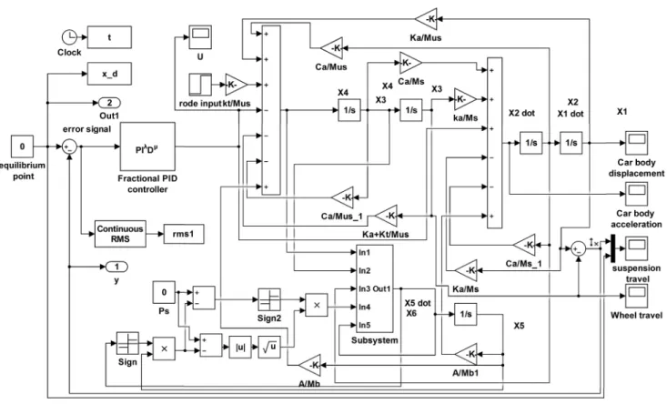
and FOPID controllers. Fig. 7 shows the controlled active suspension system model using FOPID.
In this work two controllers will control the active sus-pension system of Eqs. (3) to (9), the conventional lin-ear PID controller and by its nonlinlin-ear counterpart using the FOPID example. The simulation results of the active suspension system with the proposed controllers will be examined for the following:
• Conventional PID controller tuned by using the PID
auto tuner of MATLAB.
• Conventional PID tuned by the PSO algorithm.
• Conventional PID tuned by the WOA.
• FOPID tuned by PSO. • FOPID tuned by WOA.
Each optimization algorithm will adapt the FOPID
controller parameters in a parallel way. At first, the initial
parameters are randomly selected, then, each set of
param-eters are tested by the objective function. Comparing the
objective function for the minimum with the old one, the search is directed to the best solution. The optimiza-tion algorithm will update the parameters and continue searching for the best candidates until a stopping criterion
based on a predefined iteration limit is reached. Finally,
the controller parameters corresponding to the optimal solution by the algorithm are determined. The PSO and WOA parameters are adjusted and adapted according to the objective function as given by Eq. (21).
6.1 PID controller using the PID MATLAB autotuner
The closed-loop system is initially tested with the PID controller tuned by the PID autotuner of MATLAB tool-box, and the result is shown in Fig. 8.
It is clear that the output position of the active suspen-sion system is not acceptable as it shows high oscillations with large overshoot.
6.2 Conventional PID tuned by PSO algorithm
The PID auto tuner is insufficient to produce an accept -able controller for the active suspension system. Hence, a
more sophisticated approach is needed to refine the con -troller parameters to produce an optimum reaction.
Two evolutionary algorithms are examined to optimize the PID controller, the PSO, and the WOA. When the PSO algorithm is used with the parameters of Table 2. The PID controller parameters are established as shown in Table 3. (The results are the best out of 25 trials according to the
used fitness function.) Eq. (21), gives the fitness function
exercised for evaluating the solutions.
From Table 2, the second trail gives the best global fit -ness value with convergence as given by Fig. 9 the sus-pension travel position response and its control signal are shown in Fig. 10 and Fig. 11 respectively.
6.3 Conventional PID tuned by WOA algorithm When the WOA algorithm is used to refine the PID con -troller parameters, more than 25 experiments have been
tested and the best two trials, according to their fitness
Fig. 7 Simulink model of quarter car suspension system with FOPID controller
Table 2 Experiments for the PID-PSO based controller Trial Global Fitness using PID based PSO C1 Cognitive factor C2 Social scaling factor Number of
Iterations Number of birds
1 0.0057 3 2.7 40 150
2 0.0055 2.9 2.5 45 200
Table 3 Gains obtained by the PSO algorithm for the PID controller Gains Kp Ki Kd coefficientN Filter First trial 0.3490 1.1181 11.1617 100 Second trial 5.4231 1.4585 7.7787 100
level, are shown in Table 4. The obtained controller parameters are shown in Table 5.
From Table 4, the second trail gives the best global fit -ness, and its convergence is given by Fig. 12 the suspen-sion travel position response and its control signal are pre-sented in Fig. 13 and Fig. 14, respectively.
6.4 FOPID controller tuned by PSO
The FOPID controller tuned by the PSO is designed for the
active suspension system. The fitness functions for the best two trials out of 25 experiments are shown in Table 6.
The tuned controller parameters are shown in Table 7. Fig. 12 Fitness obtained by the WOA algorithm for the PID controller
Fig. 9 PSO fitness convergence for the PID controller
Fig. 10 Car body displacement for road input Zrt = 0.1 m
Fig. 11 PID-PSO based control signal
Table 4 Experiments for the PID-WOA based controller Trial Global Fitness using PID based WOA Number of Iterations Number of Search Agents
1 0.0053408 30 1000
2 0.0039555 50 500
Table 5 Gains obtained by the WOA algorithm for the PID controller Gains Kp Ki Kd N Filter coefficient
First trial 0.000117 0.000609 20 149.9814 Second trial 0 0.016381 20 100
The controller with the second trial is the optimum one,
the PSO fitness convergence is depicted in Fig. 15 The sus -pension travel position responses with its control signal
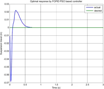
are presented in Fig. 16 and Fig. 17, respectively. 6.5 FOPID controller tuned by WOA
The active suspension system is designed by using
the FOPID controller and tuned by the WOA. The fitness
function for the best two trials out of 25 experiments is shown in Table 8. The controller parameters are shown in Table 9.
The FOPID controller with the second trial is the
opti-mal one, the WOA fitness convergence is given by Fig. 18.
Fig. 13 Car body displacement for road input Zrt = 0.1 m
Fig. 14 PID-WOA based control signal
Fig. 15 Fitness obtained by the PSO algorithm for the FOPID controller
Fig. 16 Car body displacement for road input Zrt = 0.1 m
Table 6 Experiments for the FOPID-PSO based controller Trial Global Fitness using PID based PSO C1 Cognitive factor C2 Social scaling factor Number of
Iterations Number of birds
1 0.0041 2.9 2.7 40 150
2 0.0034 3 2.6 30 180
Table 7 Gains obtained by the PSO algorithm for the FOPID controller
Gains Kp Ki λ Kd μ
First trial 1.2337 2.5642 0.5805 7.1316 1.2587 Second trial 1.7114 0.5950 0.9015 11.7206 0.9727
The response of the suspension travel position with its con-trol signal is presented in Fig. 19 and Fig. 20, respectively.
From the results of Table 2, Table 4, Table 6, and
Table 8 it can be concluded that the best controller for the active suspension system is the FOPID controller when tuned using the WOA algorithm. The large percentage of enhancement in the active suspension system appears dynamically in its overshoot and settling time in com-parison with the other controllers. The dynamic of the spring-mass displacement and acceleration are shown in Fig. 21 and Fig. 22, respectively. The wheel travel dis-placement response for the car is shown in Fig. 23.
7 Percentage of enhancement in system performance
All the results of the proposed controllers presented in
sec-tion 6 of this article are compared with previous work [5]
Fig. 18 Fitness obtained by the WOA algorithm for FOPID controller
Fig. 17 FOPID-PSO based control signal
Table 8 Experiments for the FOPID-WOA based controller Trial FOPID_WOA basedGlobal Fitness by Number of Iterations Search AgentsNumber of
1 0.001869 12 35
2 0.001736 15 20
Table 9 Gains obtained by the WOA algorithm for the FOPID controller
Gains Kp Ki Kd λ μ
First trial 1.3590 13.9481 14 0.31805 0.95873 Second trial 0.9521 14.6932 13.8755 0.05942 1.0585
Fig.19 Car body displacement for road input Zrt = 0.1 m
as given in Table 10. The main compaction factors are in the objective of minimized settling time and overshoot
of the suspension travel deflection. These two factors are
considered very important as the improvement in an
over-shoot of the suspension travel deflection will eventually
lead to increased stability in driving after exposure to road disturbances. The settling time plays a pivotal role in the ride stability with a faster response. The improved factors cause a comfortable trip and holed drive.
From the above table, it is evident that the FOPID con-troller when tuned by the PSO or WOA algorithm gives a remarkable enhancement in the measured factors.
The optimal sets of parameters are obtained when utiliz-ing the FOPID controller tuned by WOA. This optimality
comes from the ability of the WOA algorithm in finding
global minimum points over the PSO algorithm that results
in raising the global fitness finding. Table 11 illustrates
Fig. 21 Car Suspension system deflection (Sprung-mass displacement)
for road input Zrt = 0.1 m
Fig. 22 Car Suspension system acceleration (Sprung-mass acceleration)
for road input Zrt = 0.1 m
Fig. 23 Wheel Travel for the road input Zrt = 0.1 m
Table 10 Enhanced Controlled system characteristics for all proposed
controllers compared with [5]
Control method Mp (m) Settling Time tS
(sec) Percentage of enhancement over [5] Mp (m) Settling Time tS (sec) PID tuner of MATLAB 0.02800 0.92 PID-PSO based 0.02442 1.23 12.785 % -PID-WOA based 0.01504 1.57 46.285 % -FOPID-PSO based 0.01999 0.75 28.607 % 18.478 % FOPID-WOA based 0.01640 0.83 41.428 % 9.782 %
Table 11 The optimal percentage of enhancement between the propose controllers in fitness's Control method Optimal Fitness obtained by the proposed controllers Percentage of enhancement
between the fitness's of
proposed controllers (the next with the previous one) PID tuner of MATLAB 0.0121 -PID-PSO based 0.0055 54.545 % PID-WOA based 0.0039 29.090 % FOPID-PSO based 0.0034 12.820 % FOPID-WOA based 0.0017 50.000 %
the percentage of enhancement in finesse's by the proposed
controllers as optimized using the PSO and WOA algo-rithms. These enhancements are calculated for each con-troller in the table in relation to its successor concon-troller.
Fig. 24 shows a comparison for the response of the active suspension travel as the different proposed controllers are applied. It is clear that the active suspension system shows an optimal performance when designed using the FOPID controller and tuned by the WOA.
To ensuring the system performance of the approxi-mated and designed FOPID controller, and the bode
anal-ysis obtained based on the refined Oustaloup filter, the fil
-ter will use an approximation with ω = [0.01, 100] rad/s,
and order N = 5. So, via FOPID controller open loop
bode characteristic is Gm =13.8 10 dB, Φm = 70.9 degree.
These results are based on the optimized FOPID controller gains obtained via WOA, as listed in Table 9. Fig. 25 shows the bode characteristics of both controllers.
Finally, the developed controller can be digitally imple-mented using an appropriate microcontroller. A simple 8-bit Atmel - ATmega8A is one of the best choices in this case, where the microcontroller interfaced to 12-bit ana-logue-to-digital and digital-to-analogue as external
con-verters by using of the I2C interfacing technique.
8 Robustness test
The robustness test is very important to many applica-tions. System models are normally inaccurate and prone to approximations for different reasons. It could be due to parameter uncertainty, non-modelled elements, or nonlin-earities, ageing in components. In addition, modelling might
be difficult to conduct, or even sometimes impossible. If the
robustness of the FOPID controller is proved, then it tends to keep the suspension system to perform dynamically in an optimum way. This eventually increases the system sta-bility in riding, in addition to comfort travelling incipit of exposure to external road disturbances. The substantially achieves a raise and stable ride. The robustness can be tested for the control systems via simulation, by introducing some plant and controller parameters variations.
8.1 Parameter variations in the suspension system
The variation in plant parameters are examined by moni-toring the system dynamic characteristics not
exceed-ing a change of ±1 % percent. Accordexceed-ing to this criterion,
it is found that the system model parameter variation limit
of ±12 % out of its nominal values will keep its dynamic
characteristics unchanged. When the input rode disturbance become 0.2 m (doubled), the performance of the suspension system with the FOPID controller under the effect of model
parameter variations still acceptable, as illustrated in Fig. 26.
The settling time and the overshoot values stay in a range of values resulted using FOPID–WOA based con-troller, as mentioned in Table 10, with the position response staying unaffected, the same way as shown in Fig. 21.
8.2 Parameter variations in the FOPID controller
The controller of the active suspension system can be affected
by the external circumstances of the car, specifically due to
inaccurate components comprising the designed controller and/or due to the heat that may directly affect the electron-ics working. The variation in controller parameters is also
Fig. 25 Open-loop frequency response characteristics comparison for the controlled system
emulated via changing one parameter at a time to determine the limit of variation that will keep the dynamics unchanged
within ±1 %. Table 12 illustrates these boundaries of varia -tion for each controller parameter.
The settling time and the overshoot values stay in the acceptable range shown in Table 10. The characteristics of the position response of the active suspension system
with the FOPID–WOA controller stays bounded by ±1 %
as presented in Fig. 19 in spite of any variations in the con-troller parameters as given by Table 12.
9 Conclusion
To improve the performance of an active suspension sys-tem, aiming at improving the ride comfort and road hold-ing ability, it is noticed that there are other factors that need to be considered for raising the car holding and stability in the road with comfortable passenger travelling. In this paper, the minimum car body displacement and mini-mum oscillation time after exposing to road disturbances
(cusp or holes) are proved to contribute to raising the car holding and stability. An optimum robust controller for an active quarter car suspension system is designed for the presented goals. Minimizing the displacement of the car body and reducing the damping frequency of oscillation time are achieved via a nonlinear control strat-egy using the FOPID controller. The FOPID controller is designed based on PSO and WOA and shown to produce an optimized controller that maintains these characteris-tics. The parameters tuning of FOPID controller for the active suspension system by using WOA has better char-acteristics than that reached by the PSO. Robustness of the FOPID controller is examined and proved to
with-stand a system parameter variation of ±12 % in all sys
-tem parameters and of maximum of ±80 % in controller
parameter changing. A simulation outcome also indicates a considerably improved performance of the FOPID based WOA controller in comparison to the traditional PID one. The FOPID controller provides a faster speed response of the suspension system with smaller overshoot, shorter setting time, and shorter rise time than the PID controller does. In real practical engineering applications, the factor of overshoot is the most concerning one of all parame-ters. The controller that can provide a small overshoot and shorter settling time in system response can ensure the minimum car displacement and oscillation after exposing to road disturbances.
Fig. 26 Active suspension system with ±12 % variation in all system
parameters, for input of Zrt = 0.2 m
Table 12 Maximum limit of variation in FOPID-WOA controller parameters without affecting the active suspension system dynamics
Controller
parameter Optimal response values obtained by WOA Percentage of change
Kp 0.9521 ±66 % Ki 14.69326 ±14.285 % λ 0.059421 ±80 % Kd 13.8755 ±7.142 % μ 1.0585 ±1.904 % References
[1] Kumar, M. S. "Development of Active Suspension System
for Automobiles using PID Controller", In: World Congress
on Engineering, London, UK, 2008, pp. 1472–1477. [online] Available at: http://www.iaeng.org/publication/WCE2008/
[Accessed: 09 June 2019]
[2] Aldair, A. A., Wang, W. J. "Design of Fractional Order Controller
Based on Evolutionary Algorithm for a Full Vehicle Nonlinear
Active Suspension Systems", International Journal of Control and Automation, 3(4), pp. 33–46, 2010. [online] Available at:
http://arti-cle.nadiapub.com/IJCA/vol3_no4/4.pdf [Accessed: 13 March 2019]
[3] Pekgökgöz, R. K., Gürel, M. A., Bilgehan, M., Kısa, M. "Active Suspension of Cars Using Fuzzy Logic Controller Optimized
by Genetic Algorithm", International Journal of Engineering and Applied Sciences, 2(4), pp. 27–37, 2010. [online] Available at: https://
dergipark.org.tr/ijeas/issue/23576/251137 [Accessed: 25 March 2019] [4] Nagarkar, M. P., Vikhe, G. J., Borole, K. R., Nandedkar, V. M.
"Active Control of Quarter-car Suspension System Using Linear
Quadratic Regulator", International Journal of Automotive and
Mechanical Engineering (IJAME), 3, pp. 364–372, 2011. https://doi.org/10.15282/ijame.3.2011.11.0030
[5] Mouleeswaran, S. "Design and Development of PID
Controller-Based Active Suspension System for Automobiles", In: Vagia, M.
(ed.) PID Controller Design Approaches: Theory, Tuning and Application to Frontier Areas, IntechOpen, Rijeka, Croatia, 2012,
pp. 71–98.
https://doi.org/10.5772/32611
[6] Goga, V., Kľúčik, M. "Optimization of Vehicle Suspension Parameters with use of Evolutionary Computation", Procedia
Engineering, 48, pp. 174–179, 2012.
https://doi.org/10.1016/j.proeng.2012.09.502
[7] Aly, A. A., Salem, F. A. "Vehicle Suspension Systems Control: A Review", International Journal of Control, Automation and Systems, 2(2), pp. 46–54, 2013. [online] Available at: http://researchpub.org/journal/jac/number/vol2-no2/vol2-no2-6.pdf
[Accessed: 02 June 2019]
[8] Sun, W., Gao, H., Yao, B. "Adaptive Robust Vibration Control of Full-Car Active Suspensions With Electrohydraulic Actuators", IEEE Transactions on Control Systems Technology, 21(6),
pp. 2417–2422, 2013.
https://doi.org/10.1109/TCST.2012.2237174
[9] Sun, W., Pan, H., Gao, H. "Filter-Based Adaptive Vibration
Control for Active Vehicle Suspensions with Electrohydraulic Actuators", IEEE Transactions on Vehicular Technology, 65(6), pp. 4619–4626, 2016.
https://doi.org/10.1109/TVT.2015.2437455
[10] Yao, J., Shi, W., Zheng, J., Zhou, H. "Development of a sliding mode controller for semi-active vehicle suspensions", Journal of
Vibration and Control, 19(8), pp. 1152–1160, 2013. https://doi.org/10.1177/1077546312441045
[11] Guo, L.-X., Zhang, L.-P. "Robust H∞ control of active vehicle suspension under non-stationary running", Journal of Sound and
Vibration, 331(26), pp. 5824–5837, 2012. https://doi.org/10.1016/j.jsv.2012.07.042
[12] Wang, R., Jing, H., Karimi, H. R., Chen, N. "Robust fault-toler -ant H∞ control of active suspension systems with finite-frequency constraint", Mechanical Systems and Signal Processing, 62–63,
pp. 341–355, 2015.
https://doi.org/10.1016/j.ymssp.2015.01.015
[13] Ozer, H. O., Sayin, A., Korkmaz, N., Yagiz, N. "Genetic Algorithm
Integrated Sliding Mode Control of a Vehicle", In: 11th World Congress on Computational Mechanics (WCCM XI), Barcelona, Spain, 2014, pp. 3857–3868. [online] Available at: http://www.
cimne.com/compdesmat/vpage/1/0/Downloads/Conference-proceedings-and-extended-abstracts [Accessed: 15 January 2019]
[14] Drehmer, L. R. C., Paucar Casas, W. J., Gomes, H. M. "Parameters
optimization of a vehicle suspension system using a particle swarm optimization algorithm", Vehicle System Dynamics: International Journal of Vehicle Mechanics and Mobility, 53(4), pp. 449–474, 2015.
https://doi.org/10.1080/00423114.2014.1002503
[15] Dong, X., Zhao, D., Yang, B., Han, C. "Fractional-order control of
active suspension actuator based on parallel adaptive clonal selec-tion algorithm", Journal of Mechanical Science and Technology,
30(6), pp. 2769–2781, 2016.
https://doi.org/10.1007/s12206-016-0538-2
[16] Deshpande, V. S., Shendge, P. D., Phadke, S. B. "Dual objective
active suspension system based on a novel nonlinear disturbance compensator", Vehicle System Dynamics: International Journal of
Vehicle Mechanics and Mobility, 54(9), pp. 1269–1290, 2016. https://doi.org/10.1080/00423114.2016.1198490
[17] Concilio, A., De Simone, M. C., Rivera, Z. B., Guida, D. "Razvoj i implementacija sistema upravljanja kod rekonstruisane CNC
mašine primenom Arduino platforme" (A new semi-active suspen-sion system for racing vehicles), FME Transactions, 45(4), pp. 578– 584, 2017. (in Bosnian)
https://doi.org/doi:10.5937/fmet1704578C
[18] Fu, Z.-J, Li, B., Ning, X.-B., Xie, W.-D. "Online Adaptive Optimal
Control of Vehicle Active Suspension Systems Using
Single-Network Approximate Dynamic Programming", Mathematical
Problems in Engineering, 2017, Article ID: 4575926, 2017. https://doi.org/10.1155/2017/4575926
[19] Xue, W., Li, K., Chen, Q., Liu, G. "Mixed FTS/H∞ control of
vehicle active suspensions with shock road disturbance", Vehicle System Dynamics: International Journal of Vehicle Mechanics and
Mobility, 57(6), pp.841–854, 2018.
https://doi.org/10.1080/00423114.2018.1490023
[20] Podlubny, I. "Fractional-Order Systems and PIλDμ-Controllers",
IEEE Transactions on Automatic Control, 44(1), pp. 208–214, 1999. https://doi.org/10.1109/9.739144
[21] Tepljakov, A., Petlenkov, E., Belikov, J., Astapov, S. "Tuning and
Digital Implementation of a Fractional-Order PD Controller for a
Position Servo", International Journal of Microelectronics and
Computer Science, 4(3), pp. 116–123, 2013. [online] Available
at: https://yadda.icm.edu.pl/baztech/element/bwmeta1.element.
baztech-9b74550a-6a22-44cc-8486-f0691fccaa73/c/Tepljakov_
Petlenkov_Belikov_Astapov_Tuning_3_2013.pdf [Accessed: 27 March 2019]
[22] Taher, S. A., Hajiakbari Fini, M., Falahati Aliabadi, S. "Fractional
order PID controller design for LFC in electric power systems
using imperialist competitive algorithm", Ain Shams Engineering Journal, 5(1), pp. 121–135, 2014.
https://doi.org/10.1016/j.asej.2013.07.006
[23] Tepljakov, A., Petlenkov, E., Belikov, J. "A Flexible MATLAB
Tool for Optimal Fractional-order PID Controller Design Subject to Specifications", In: Proceedings of the 31st Chinese Control Conference, Hefei, China, 2012, pp. 4698–4703. [online] Available
at: https://ieeexplore.ieee.org/document/6390753 [Accessed: 27 January 2019]
[24] Choudhary, S. K. "Stability and Performance Analysis of Fractional Order Control Systems", Wseas Transactions on Systems and Control, 9(45), pp. 438–444, 2014. [online] Available at: http:// eprints.manipal.edu/id/eprint/141489 [Accessed: 05 February 2019]
[25] Anantachaisilp, P., Lin, Z. "Fractional Order PID Control of Rotor Suspension by Active Magnetic Bearings", Actuators, 6(1),
Article number: 4, 2017.
[26] Hassan, M. Y., Karam, Z. A. "Force-Position Controller Design for 4
Dof's Rehabilitation Robot Arm using PSO Algorithm", International Journal of Information Technology and Business Management, 39(1), pp. 84–98, 2015. Available at: https://www.jitbm.com/JITBM%20 39th%20volume/7%20REHABILITATION%20ROBOT%20ARM.
pdf [Accessed: 24 March 2019]
[27] Alfi, A., Fateh, M. M. "Identification of nonlinear systems using modified particle swarm optimization: a hydraulic suspension sys -tem", Vehicle System Dynamics: International Journal of Vehicle
Mechanics and Mobility, 49(6), pp. 871–887, 2011. https://doi.org/10.1080/00423114.2010.497842
[28] Chen, J., Qin, Z., Liu, Y., Lu, J. "Particle Swarm Optimization with Local Search", In: 2005 International Conference on Neural Networks and Brain, Beijing, China, 2005, pp. 481–484.
https://doi.org/10.1109/ICNNB.2005.1614658
[29] He, Y., Liu, K. "A Modified Particle Swarm Optimization for Solving Global Optimization Problems", In: 2006 International Conference on Machine Learning and Cybernetics, Dalian, China, 2006, pp. 2173–2177.
https://doi.org/10.1109/ICMLC.2006.258615
[30] MathWorks "Genetic Algorithm and Direct Search Toolbox", The MathWorks, Inc., Natick, MA, USA, 2004. [online] Available at: http://cda.psych.uiuc.edu/matlab_pdf/gads_tb.pdf [Accessed:
26 December 2018]
[31] Mirjalili, S., Lewis, A. "The Whale Optimization Algorithm",
Advances in Engineering Software, 95, pp. 51–67, 2016. https://doi.org/10.1016/j.advengsoft.2016.01.008
[32] Mafarja, M. M., Mirjalili, S. "Hybrid Whale Optimization Algorithm with simulated annealing for feature selection", Neurocomputing,
260, pp. 302–312, 2017.
https://doi.org/10.1016/j.neucom.2017.04.053
[33] Karam, Z. A., Ghintab, S. S., Hasan, S. "Rapidly-implementable optimizely-sizable fuzzy controller architectures: A performance analysis for semiconductor packaging two axes table", Periodicals
of Engineering and Natural Sciences, 7(2), pp. 644–659, 2019. https://doi.org/10.21533/pen.v7i2.548
![Table 1 Parameters of a quarter active car suspension system [5, 7]](https://thumb-us.123doks.com/thumbv2/123dok_us/607988.2572827/4.892.68.421.489.830/table-parameters-of-quarter-active-car-suspension-system.webp)
![Fig. 5 Hunting process of Bubble-net feeding for humpback whales [32]](https://thumb-us.123doks.com/thumbv2/123dok_us/607988.2572827/7.892.474.821.147.376/fig-hunting-process-bubble-net-feeding-humpback-whales.webp)
![Fig. 6 PID-PSO based controller block diagram [33]](https://thumb-us.123doks.com/thumbv2/123dok_us/607988.2572827/8.892.466.790.147.291/fig-pid-pso-based-controller-block-diagram.webp)

![Table 10 Enhanced Controlled system characteristics for all proposed controllers compared with [5]](https://thumb-us.123doks.com/thumbv2/123dok_us/607988.2572827/13.892.95.430.529.833/table-enhanced-controlled-characteristics-proposed-controllers-compared.webp)
