http://www.3com.com/
NBX
®Installation Guide
Release 4.3
■ SuperStack 3 NBX
■ NBX 100
3Com Corporation 350 Campus Drive Marlborough, MA 01752-3064
Copyright © 2004, 3Com Corporation. All rights reserved. No part of this documentation may be reproduced in any form or by any means or used to make any derivative work (such as translation, transformation, or adaptation) without written permission from 3Com Corporation.
3Com Corporation reserves the right to revise this documentation and to make changes in content from time to time without obligation on the part of 3Com Corporation to provide notification of such revision or change. 3Com Corporation provides this documentation without warranty, term, or condition of any kind, either implied or expressed, including, but not limited to, the implied warranties, terms, or conditions of merchantability, satisfactory quality, and fitness for a particular purpose. 3Com may make improvements or changes in the product(s) and/or the program(s) described in this documentation at any time.
If there is any software on removable media described in this documentation, it is furnished under a license agreement included with the product as a separate document, in the hardcopy documentation, or on the removable media in a directory file named LICENSE.TXT or !LICENSE.TXT. If you are unable to locate a copy, please contact 3Com and a copy will be provided to you.
UNITED STATES GOVERNMENT LEGEND
If you are a United States government agency, then this documentation and the software described herein are provided to you subject to the following:
All technical data and computer software are commercial in nature and developed solely at private expense. Software is delivered as “Commercial Computer Software” as defined in DFARS 252.227-7014 (June 1995) or as a “commercial item” as defined in FAR 2.101(a) and as such is provided with only such rights as are provided in 3Com’s standard commercial license for the Software. Technical data is provided with limited rights only as provided in DFAR 252.227-7015 (Nov 1995) or FAR 52.227-14 (June 1987), whichever is applicable. You agree not to remove or deface any portion of any legend provided on any licensed program or documentation contained in, or delivered to you in conjunction with, this guide.
_______________________________________________________________________ PATENT INFORMATION
NBX Telephones 3C10281PE, 3C10226PE, 3C10228IRPE, and 3C10248PE are covered by one or more of the following U.S. patents and other patent applications pending:
5,994,998; 6,140,911; 6,329,906; 6,496,105; 6,535,983; 6,483,203; 6,449,348; 6,212,195 _______________________________________________________________________ TRADEMARKS
Unless otherwise indicated, 3Com registered trademarks are registered in the United States and may or may not be registered in other countries. 3Com, NBX, the 3Com logo, and SuperStack are registered trademarks of 3Com Corporation. NBX NetSet and pcXset are trademarks of 3Com Corporation.
Adobe is a trademark and Adobe Acrobat is a registered trademark of Adobe Systems Incorporated. InstallShield is a registered trademark of InstallShield Software Corporation. Internet Explorer, Microsoft, Windows, Windows 2000, and Windows NT are registered trademarks of Microsoft Corporation. Netscape and Netscape Navigator are registered trademarks of Netscape Communication Corporation in the United States and other countries. All other company and product names may be trademarks of the respective companies with which they are associated.
_______________________________________________________________________ TECHNOLOGY ACKNOWLEDGEMENTS
_______________________________________________________________________ RSA Data Security, Inc. MD5 Message-Digest Algorithm
Copyright © 1991-2, RSA Data Security, Inc. Created 1991. All rights reserved.
License to copy and use this software is granted provided that it is identified as the “RSA Data Security, Inc. MD5 Message-Digest Algorithm” in all material mentioning or referencing this software or this function. License is also granted to make and use derivative works provided that such works are identified as “derived from the RSA Data Security, Inc. MD5 Message-Digest Algorithm” in all material mentioning or referencing the derived work.
RSA Data Security, Inc. makes no representations concerning either the merchantability of this software or the suitability of this software for any particular purpose. It is provided “as is” without express or implied warranty of any kind.
_________________________________________________________________________________ libtar 2.1.11
Copyright © 1998-2003 University of Illinois Board of Trustees Copyright © 1998-2003 Mark D. Roth
All rights reserved. Developed by:
Campus Information Technologies and Educational Services, University of Illinois at Urbana-Champaign Permission is hereby granted, free of charge, to any person obtaining a copy of this software and associated documentation files (the “Software”), to deal with the Software without restriction, including without limitation the rights to use, copy, modify, merge, publish, distribute, sublicense, and/or sell copies of the Software, and to permit persons to whom the Software is furnished to do so, subject to the following conditions:
■ Redistributions of source code must retain the above copyright notice, this list of conditions and the following disclaimers.
■ Redistributions in binary form must reproduce the above copyright notice, this list of conditions and the following disclaimers in the documentation and/or other materials provided with the distribution. ■ Neither the names of Campus Information Technologies and Educational Services, University of Illinois at
Urbana-Champaign, nor the names of its contributors may be used to endorse or promote products derived from this Software without specific prior written permission.
THE SOFTWARE IS PROVIDED “AS IS,” WITHOUT WARRANTY OF ANY KIND, EXPRESS OR IMPLIED, INCLUDING BUT NOT LIMITED TO THE WARRANTIES OF MERCHANTABILITY, FITNESS FOR A PARTICULAR PURPOSE AND NONINFRINGEMENT. IN NO EVENT SHALL THE CONTRIBUTORS OR COPYRIGHT HOLDERS BE LIABLE FOR ANY CLAIM, DAMAGES, OR OTHER LIABILITY, WHETHER IN AN ACTION OF CONTRACT, TORT, OR OTHERWISE, ARISING FROM, OUT OF, OR IN CONNECTION WITH THE SOFTWARE OR THE USE OR OTHER DEALINGS WITH THE SOFTWARE.
_________________________________________________________________________________ OpenBSD: basename.c,v 1.4 1999/05/30 17:10:30 espie Exp
OpenBSD: dirname.c,v 1.4 1999/05/30 17:10:30 espie Exp
Copyright © 1997 Todd C. Miller <[email protected]> All rights reserved.
Redistribution and use in source and binary forms, with or without modification, are permitted provided that the following conditions are met:
1. Redistributions of source code must retain the above copyright notice, this list of conditions and the following disclaimer.
2. Redistributions in binary form must reproduce the above copyright notice, this list of conditions and the following disclaimer in the documentation and/or other materials provided with the distribution. 3. The name of the author may not be used to endorse or promote products derived from this software without specific prior written permission.
THIS SOFTWARE IS PROVIDED “AS IS” AND ANY EXPRESS OR IMPLIED WARRANTIES, INCLUDING, BUT NOT LIMITED TO, THE IMPLIED WARRANTIES OF MERCHANTABILITY AND FITNESS FOR A PARTICULAR PURPOSE ARE DISCLAIMED. IN NO EVENT SHALL THE AUTHOR BE LIABLE FOR ANY DIRECT, INDIRECT, INCIDENTAL, SPECIAL, EXEMPLARY, OR CONSEQUENTIAL DAMAGES (INCLUDING, BUT NOT LIMITED TO, PROCUREMENT OF SUBSTITUTE GOODS OR SERVICES; LOSS OF USE, DATA, OR PROFITS; OR BUSINESS INTERRUPTION) HOWEVER CAUSED AND ON ANY THEORY OF LIABILITY, WHETHER IN CONTRACT, STRICT LIABILITY, OR TORT (INCLUDING NEGLIGENCE OR OTHERWISE) ARISING IN ANY WAY OUT OF THE USE OF THIS SOFTWARE, EVEN IF ADVISED OF THE POSSIBILITY OF SUCH DAMAGE.
_________________________________________________________________________________ OpenBSD: fnmatch.c,v 1.6 1998/03/19 00:29:59 millert Exp
Copyright © 1989, 1993, 1994 The Regents of the University of California. All rights reserved. This code is derived from software contributed to Berkeley by Guido van Rossum.
Redistribution and use in source and binary forms, with or without modification, are permitted provided that the following conditions are met:
2. Redistributions in binary form must reproduce the above copyright notice, this list of conditions and the following disclaimer in the documentation and/or other materials provided with the distribution. 3. All advertising materials mentioning features or use of this software must display the following acknowledgement:
This product includes software developed by the University of California, Berkeley and its contributors. 4. Neither the name of the University nor the names of its contributors may be used to endorse or promote products derived from this software without specific prior written permission.
THIS SOFTWARE IS PROVIDED BY THE REGENTS AND CONTRIBUTORS ``AS IS'' AND ANY EXPRESS OR IMPLIED WARRANTIES, INCLUDING, BUT NOT LIMITED TO, THE IMPLIED WARRANTIES OF MERCHANTABILITY AND FITNESS FOR A PARTICULAR PURPOSE ARE DISCLAIMED. IN NO EVENT SHALL THE REGENTS OR CONTRIBUTORS BE LIABLE FOR ANY DIRECT, INDIRECT, INCIDENTAL, SPECIAL, EXEMPLARY, OR
CONSEQUENTIAL DAMAGES (INCLUDING, BUT NOT LIMITED TO, PROCUREMENT OF SUBSTITUTE GOODS OR SERVICES; LOSS OF USE, DATA, OR PROFITS; OR BUSINESS INTERRUPTION) HOWEVER CAUSED AND ON ANY THEORY OF LIABILITY, WHETHER IN CONTRACT, STRICT LIABILITY, OR TORT (INCLUDING NEGLIGENCE OR OTHERWISE) ARISING IN ANY WAY OUT OF THE USE OF THIS SOFTWARE, EVEN IF ADVISED OF THE POSSIBILITY OF SUCH DAMAGE.
_________________________________________________________________________________ gethostname.c: minimal substitute for missing gethostname() function
created 2000-Mar-02 jmk requires SVR4 uname() and -lc by Jim Knoble <[email protected]> Copyright © 2000 Jim Knoble
Permission to use, copy, modify, distribute, and sell this software and its documentation for any purpose is hereby granted without fee, provided that the above copyright notice appear in all copies and that both that copyright notice and this permission notice appear in supporting documentation.
This software is provided “as is,” without warranty of any kind, express or implied, including but not limited to the warranties of merchantability, fitness for a particular purpose and noninfringement. In no event shall the author(s) be liable for any claim, damages or other liability, whether in an action of contract, tort or otherwise, arising from, out of or in connection with the software or the use or other dealings in the software. _________________________________________________________________________________ glob.c
Copyright © 1989, 1993
The Regents of the University of California. All rights reserved.
This code is derived from software contributed to Berkeley by Guido van Rossum.
Redistribution and use in source and binary forms, with or without modification, are permitted provided that the following conditions are met:
1. Redistributions of source code must retain the above copyright notice, this list of conditions and the following disclaimer.
2. Redistributions in binary form must reproduce the above copyright notice, this list of conditions and the following disclaimer in the documentation and/or other materials provided with the distribution. 3. All advertising materials mentioning features or use of this software must display the following acknowledgement:
This product includes software developed by the University of California, Berkeley and its contributors. 4. Neither the name of the University nor the names of its contributors may be used to endorse or promote products derived from this software without specific prior written permission.
THIS SOFTWARE IS PROVIDED BY THE REGENTS AND CONTRIBUTORS ``AS IS'' AND ANY EXPRESS OR IMPLIED WARRANTIES, INCLUDING, BUT NOT LIMITED TO, THE IMPLIED WARRANTIES OF MERCHANTABILITY AND FITNESS FOR A PARTICULAR PURPOSE ARE DISCLAIMED. IN NO EVENT SHALL THE REGENTS OR CONTRIBUTORS BE LIABLE FOR ANY DIRECT, INDIRECT, INCIDENTAL, SPECIAL, EXEMPLARY, OR
_________________________________________________________________________________ OpenBSD: strdup.c,v 1.3 1997/08/20 04:18:52 millert Exp
Copyright © 1988, 1993
The Regents of the University of California. All rights reserved.
Redistribution and use in source and binary forms, with or without modification, are permitted provided that the following conditions are met:
1. Redistributions of source code must retain the above copyright notice, this list of conditions and the following disclaimer.
2. Redistributions in binary form must reproduce the above copyright notice, this list of conditions and the following disclaimer in the documentation and/or other materials provided with the distribution. 3. All advertising materials mentioning features or use of this software must display the following acknowledgement:
This product includes software developed by the University of California, Berkeley and its contributors. 4. Neither the name of the University nor the names of its contributors may be used to endorse or promote products derived from this software without specific prior written permission.
THIS SOFTWARE IS PROVIDED BY THE REGENTS AND CONTRIBUTORS “AS IS” AND ANY EXPRESS OR IMPLIED WARRANTIES, INCLUDING, BUT NOT LIMITED TO, THE IMPLIED WARRANTIES OF MERCHANTABILITY AND FITNESS FOR A PARTICULAR PURPOSE ARE DISCLAIMED. IN NO EVENT SHALL THE REGENTS OR CONTRIBUTORS BE LIABLE FOR ANY DIRECT, INDIRECT, INCIDENTAL, SPECIAL, EXEMPLARY, OR
CONSEQUENTIAL DAMAGES (INCLUDING, BUT NOT LIMITED TO, PROCUREMENT OF SUBSTITUTE GOODS OR SERVICES; LOSS OF USE, DATA, OR PROFITS; OR BUSINESS INTERRUPTION) HOWEVER CAUSED AND ON ANY THEORY OF LIABILITY, WHETHER IN CONTRACT, STRICT LIABILITY, OR TORT (INCLUDING NEGLIGENCE OR OTHERWISE) ARISING IN ANY WAY OUT OF THE USE OF THIS SOFTWARE, EVEN IF ADVISED OF THE POSSIBILITY OF SUCH DAMAGE.
_________________________________________________________________________________ OpenBSD: strlcat.c,v 1.5 2001/01/13 16:17:24 millert Exp
OpenBSD: strlcpy.c,v 1.4 1999/05/01 18:56:41 millert Exp Copyright © 1998 Todd C. Miller <[email protected]> All rights reserved.
Redistribution and use in source and binary forms, with or without modification, are permitted provided that the following conditions are met:
1. Redistributions of source code must retain the above copyright notice, this list of conditions and the following disclaimer.
2. Redistributions in binary form must reproduce the above copyright notice, this list of conditions and the following disclaimer in the documentation and/or other materials provided with the distribution. 3. The name of the author may not be used to endorse or promote products derived from this software without specific prior written permission.
_________________________________________________________________________________ strmode.c
Copyright © 1990 The Regents of the University of California. All rights reserved.
Redistribution and use in source and binary forms, with or without modification, are permitted provided that the following conditions are met:
1. Redistributions of source code must retain the above copyright notice, this list of conditions and the following disclaimer.
2. Redistributions in binary form must reproduce the above copyright notice, this list of conditions and the following disclaimer in the documentation and/or other materials provided with the distribution. 3. All advertising materials mentioning features or use of this software must display the following acknowledgement:
This product includes software developed by the University of California, Berkeley and its contributors. 4. Neither the name of the University nor the names of its contributors may be used to endorse or promote products derived from this software without specific prior written permission.
THIS SOFTWARE IS PROVIDED BY THE REGENTS AND CONTRIBUTORS ``AS IS'' AND ANY EXPRESS OR IMPLIED WARRANTIES, INCLUDING, BUT NOT LIMITED TO, THE IMPLIED WARRANTIES OF MERCHANTABILITY AND FITNESS FOR A PARTICULAR PURPOSE ARE DISCLAIMED. IN NO EVENT SHALL THE REGENTS OR CONTRIBUTORS BE LIABLE FOR ANY DIRECT, INDIRECT, INCIDENTAL, SPECIAL, EXEMPLARY, OR
CONSEQUENTIAL DAMAGES (INCLUDING, BUT NOT LIMITED TO, PROCUREMENT OF SUBSTITUTE GOODS OR SERVICES; LOSS OF USE, DATA, OR PROFITS; OR BUSINESS INTERRUPTION) HOWEVER CAUSED AND ON ANY THEORY OF LIABILITY, WHETHER IN CONTRACT, STRICT LIABILITY, OR TORT (INCLUDING NEGLIGENCE OR OTHERWISE) ARISING IN ANY WAY OUT OF THE USE OF THIS SOFTWARE, EVEN IF ADVISED OF THE POSSIBILITY OF SUCH DAMAGE.
_________________________________________________________________________________ OpenBSD: strsep.c,v 1.3 1997/08/20 04:28:14 millert Exp
Copyright © 1990, 1993
The Regents of the University of California. All rights reserved.
Redistribution and use in source and binary forms, with or without modification, are permitted provided that the following conditions are met:
1. Redistributions of source code must retain the above copyright notice, this list of conditions and the following disclaimer.
2. Redistributions in binary form must reproduce the above copyright notice, this list of conditions and the following disclaimer in the documentation and/or other materials provided with the distribution. 3. All advertising materials mentioning features or use of this software must display the following acknowledgement:
This product includes software developed by the University of California, Berkeley and its contributors. 4. Neither the name of the University nor the names of its contributors may be used to endorse or promote products derived from this software without specific prior written permission.
THIS SOFTWARE IS PROVIDED BY THE REGENTS AND CONTRIBUTORS “AS IS” AND ANY EXPRESS OR IMPLIED WARRANTIES, INCLUDING, BUT NOT LIMITED TO, THE IMPLIED WARRANTIES OF MERCHANTABILITY AND FITNESS FOR A PARTICULAR PURPOSE ARE DISCLAIMED. IN NO EVENT SHALL THE REGENTS OR CONTRIBUTORS BE LIABLE FOR ANY DIRECT, INDIRECT, INCIDENTAL, SPECIAL, EXEMPLARY, OR
_________________________________________________________________________________ zlib.h — Interface of the “zlib” general-purpose compression library, version 1.1.4, March 11th, 2002 Copyright © 1995-2002 Jean-loup Gailly and Mark Adler
This software is provided “as-is”, without any express or implied warranty. In no event will the authors be held liable for any damages arising from the use of this software.
Permission is granted to anyone to use this software for any purpose, including commercial applications, and to alter it and redistribute it freely, subject to the following restrictions:
1. The origin of this software must not be misrepresented; you must not claim that you wrote the original software. If you use this software in a product, an acknowledgment in the product documentation would be appreciated but is not required.
2. Altered source versions must be plainly marked as such, and must not be misrepresented as being the original software.
3. This notice may not be removed or altered from any source distribution. — Jean-loup Gailly [email protected]
— Mark Adler [email protected]
_________________________________________________________________________________ imapproxy
© Copyright 1993, 1994 by Carnegie Mellon University. All Rights Reserved.
Permission to use, copy, modify, distribute, and sell this software and its documentation for any purpose is hereby granted without fee, provided that the above copyright notice appear in all copies and that both that copyright notice and this permission notice appear in supporting documentation, and that the name of Carnegie Mellon University not be used in advertising or publicity pertaining to distribution of the software without specific, written prior permission. Carnegie Mellon University makes no representations about the suitability of this software for any purpose. It is provided “as is” without express or implied warranty. CARNEGIE MELLON UNIVERSITY DISCLAIMS ALL WARRANTIES WITH REGARD TO THIS SOFTWARE, INCLUDING ALL IMPLIED WARRANTIES OF MERCHANTABILITY AND FITNESS, IN NO EVENT SHALL CARNEGIE MELLON UNIVERSITY BE LIABLE FOR ANY SPECIAL, INDIRECT, OR CONSEQUENTIAL DAMAGES OR ANY DAMAGES WHATSOEVER RESULTING FROM LOSS OF USE, DATA, OR PROFITS, WHETHER IN AN ACTION OF CONTRACT, NEGLIGENCE, OR OTHER TORTUOUS ACTION, ARISING OUT OF OR IN CONNECTION WITH THE USE OR PERFORMANCE OF THIS SOFTWARE.
_________________________________________________________________________________ imap daemon
Program: IMAP4rev1 server Author: Mark Crispin
Networks and Distributed Computing
Computing & Communications, Administration Building, AG-44 University of Washington
Seattle, WA 98195
Internet: [email protected] Date: 5 November 1990
Last Edited: 6 January 1997
Copyright © 1997 by the University of Washington
_________________________________________________________________________________ imapclient
Author: Mark Crispin
Networks and Distributed Computing
Computing & Communications, Administration Building, AG-44, University of Washington
Seattle, WA 98195
Internet: [email protected] Date: 22 November 1989
Last Edited: 9 January 1998
Copyright © 1998 by the University of Washington
Permission to use, copy, modify, and distribute this software and its documentation for any purpose and without fee is hereby granted, provided that the above copyright notice appears in all copies and that both the above copyright notice and this permission notice appear in supporting documentation, and that the name of the University of Washington not be used in advertising or publicity pertaining to distribution of the software without specific, written prior permission. This software is made available “as is”, and THE UNIVERSITY OF WASHINGTON DISCLAIMS ALL WARRANTIES, EXPRESS OR IMPLIED, WITH REGARD TO THIS SOFTWARE, INCLUDING WITHOUT LIMITATION ALL IMPLIED WARRANTIES OF MERCHANTABILITY AND FITNESS FOR A PARTICULAR PURPOSE, AND IN NO EVENT SHALL THE UNIVERSITY OF WASHINGTON BE LIABLE FOR ANY SPECIAL, INDIRECT OR CONSEQUENTIAL DAMAGES OR ANY DAMAGES WHATSOEVER RESULTING FROM LOSS OF USE, DATA OR PROFITS, WHETHER IN AN ACTION OF CONTRACT, TORT (INCLUDING NEGLIGENCE) OR STRICT LIABILITY, ARISING OUT OF OR IN CONNECTION WITH THE USE OR PERFORMANCE OF THIS SOFTWARE.
_________________________________________________________________________________ IMAP\imapproxy\amigados.c, IMAP\imapproxy\amigpk.c, and IMAP\imapproxy\amigaunpk.c © Copyright 1993 by Mike W. Meyer
Permission to use, copy, modify, distribute, and sell this software and its documentation for any purpose is hereby granted without fee, provided that the above copyright notice appear in all copies and that both that copyright notice and this permission notice appear in supporting documentation, and that the name of Mike W. Meyer not be used in advertising or publicity pertaining to distribution of the software without specific, written prior permission. Mike W. Meyer makes no representations about the suitability of this software for any purpose. It is provided “as is” without express or implied warranty.
C
ONTENTS
A
BOUTT
HISG
UIDEHow to Use This Guide 17
Conventions 18
International Terminology 18
Your Comments on the Technical Documentation 19
1
I
NTRODUCTIONSuperStack 3 NBX Core Components 22
SuperStack 3 NBX Call Processor 22
SuperStack 3 NBX Gateway Chassis 24
NBX 100 Core Components 25
NBX 100 6-Slot Chassis 25
NBX 100 Call Processor 27
Overview of NBX Cards and Devices 29
Analog Line Card 29
T1 Digital Line Card 30
E1 Digital Line Card 34
BRI-ST Digital Line Card 37
10BASE-T Uplink Card 38
Analog Terminal Card 38
Analog Terminal Adapters 40
3Com Telephones 42
Attendant Console 45
Third-party Devices 45
System Configuration Guidelines 47
Total Device Limits on the NBX System 47
Individual Device Limits 48
Licensed Device Limits 48
How the Three Limit Types Interact 48
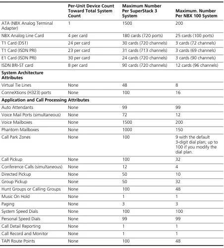
Table of Maximum Device Counts 49
2
I
NSTALLINGS
YSTEMH
ARDWAREC
OMPONENTSIntroduction 52
International Feature Support 52
Power Fail Transfer 52
Analog Terminal Connectors 52
Language Support 52
Installation Requirements 53
Electrical Requirements 53
Environmental Requirements 53
Physical Requirements 54
Local Telephone Service 55
Installation Questions 55
Who Should Install the NBX System? 55
Does the Telephone Company Need to Be Involved? 56
Can Existing Office Telephone Wires Be Reused? 56
Is Any Additional Equipment Required? 56
What External Devices Can Connect to an NBX System? 57
How Many Telephones or Devices Does the NBX System Support? 58
What Effect Does an NBX System Have on a LAN? 58
Before You Begin Installation 60
Required and Recommended Tools and Equipment 60
Important Safety Information 61
Lithium Battery Safety 64
Consignes Importantes de Sécurité 64
Batterie au lithium 66
Wichtige Sicherheitsinformationen 66
Lithiumbatterie 67
Unpacking and Examining the Components 68
Recording MAC Addresses 68
Installing the Disk Drive 69
Mounting the NBX 100 Chassis 71
Powering Your NBX 100 System 74
Installing the SuperStack 3 NBX System 74
Rack-mounting the SuperStack 3 NBX Call Processor 74
Mounting the NBX Gateway Chassis 75
Installing a Second Disk for Disk Mirroring 76
Powering Your SuperStack 3 NBX System 77
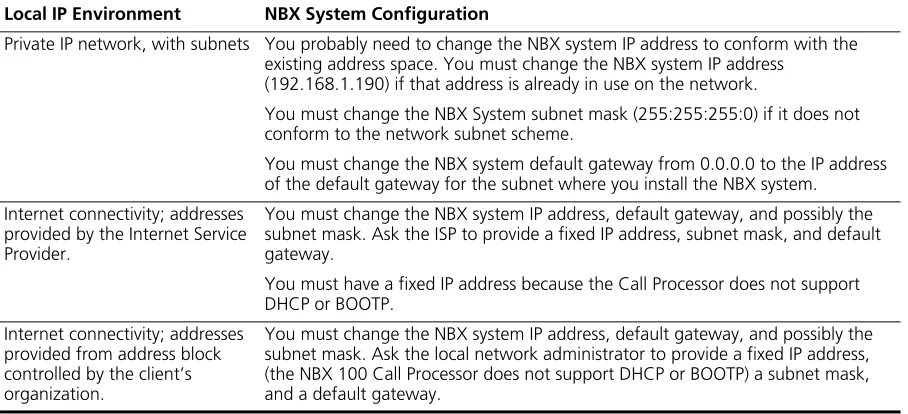
Configuring NBX System Networking 78
Establishing IP Connectivity 79
Modifying Default IP Settings 79
Configuring IP Addresses for Your LAN 82
Establishing LAN Connections 82
Connecting Cards and Devices 83
Connecting Analog Line Cards 84
Connecting Digital Line Cards 85
Connecting Analog Terminal Cards 85
Connecting an Analog Terminal Adapter 86
Connecting a 3Com Attendant Console 88
Selecting Regional Software and Components 90
Installing Regional Software and Components 90
Using Auto Discover for Initial System Configuration 91
Initial System Configuration 93
Disabling the Auto Discover Feature 95
Configuring the Operating Mode 95
Reassigning Extensions and Setting Line Card Port Options 96
Connecting Telephone Lines 100
Adding External Hardware 100
Connecting a Music-on-Hold (MOH) Input Device 100
Connecting a Paging Amplifier 100
Configuring Routing Devices 101
3
T
ELEPHONESANDA
TTENDANTC
ONSOLESAdding Telephones 103
Adding Telephones During System Installation 103
Adding a 3Com Attendant Console 113
Verifying Extension Assignments on an Attendant Console 117
Attendant Console Labels 117
Adding a Remote Telephone 118
4
A
NALOGL
INEC
ARDSAuto Discover Analog Line Cards 119
Inserting an Analog Line Card 120
Verifying an Analog Line Card 120
Using the NBX NetSet Utility 120
Using Status Lights 121
5
A
NALOGD
EVICESAdding an Analog Terminal Card 124
Inserting an Analog Terminal Card 125
Verifying Analog Terminal Card Ports 126
Using the NBX NetSet Utility 126
Using Status Lights 127
Adding an Analog Terminal Adapter (ATA) 128
Connecting the Analog Terminal Adapter 129
Verifying an Analog Terminal Adapter 130
Using Status Lights 131
6
BRI-ST D
IGITALL
INEC
ARDAdding a BRI-ST Digital Line Card 134
Preparing the NBX System for BRI Cards 134
Ordering DID, CLIP, and MSN Services for BRI 134
Enabling the Auto Discover Feature 135
Inserting the BRI-ST Digital Line Card 135
Verifying a BRI-ST Digital Line Card 136
Using the NBX NetSet Utility 136
Using Status Lights 136
7
E1 ISDN PRI D
IGITALL
INEC
ARDAdding an E1 Digital Line Card 140
Ordering DID, CLIP, and MSN Services for E1 140
Enabling the Auto Discover Feature for Digital Line Cards 141
Inserting the E1 Digital Line Card 141
Verifying an E1 Digital Line Card 142
Using the NBX NetSet Utility 142
Using the Status Lights 143
8
T1 D
IGITALL
INEC
ARDAdding a T1 Digital Line Card 146
Preparing the NBX System for a T1 Card 146
Ordering DID (Direct Inward Dialing) Services for T1 146
Enabling Auto Discover for Digital Line Cards 147
Inserting the T1 Digital Line Card 147
Verifying the T1 Digital Line Card 148
Using the NBX NetSet Utility 148
Using the Status Lights 149
9
C
ONFIGURINGIP T
ELEPHONYIP Telephony Overview 152
Implementing IP 152
Standard IP Configuration 153
IP On-the-Fly Configuration 154
Providing the NCP IP Address to Devices 154
Configuring IP Telephony 155
Selecting the Operating Mode 155
Configuring IP On-the-Fly 156
Configuring the DHCP Server 157
Manually Configuring Telephone IP Settings 157
Entering Data Using the Telephone Key Pad 158
Automatically Configuring Telephone IP Settings 159
Configuring Analog Line Card Ports 159
Configuring T1, E1, and BRI Channels 160
Low-bandwidth Telephony 161
10
T
ROUBLESHOOTINGSystem-level Troubleshooting 166
Connecting a Computer to a Serial Port 168
Servicing the Network Call Processor Battery 170
Getting Service and Support 170
A
S
PECIFICATIONSGovernment Approvals 172
Safety 172
EMC Emissions 172
EMC Immunity 172
European Community CE Notice 172
Other Approvals 172
SuperStack 3 NBX Call Processor 173
SuperStack 3 NBX Gateway Chassis 174
NBX 100 Call Processor 174
NBX 100 6-Slot Chassis 175
NBX Analog Line Cards 176
3C10114 176
3C10114C 177
NBX Analog Terminal Cards 178
3C10117 178
3C210117C 178
NBX Analog Terminal Adapter (ATA) 178
NBX BRI-ST Digital Line Card 179
NBX E1 and T1 Digital Line Cards 179
NBX Hub Card 179
NBX Uplink Card 179
3Com 3102 Business Telephone 180
3Com 2102 and 2102-IR Business Telephones 180
3Com 1102 Business Telephone 181
3Com 3101 Basic Telephone 182
3Com 2101 Basic Telephone 182
3Com 3105 Attendant Console 183
B
C
IRCUITP
ROVISIONINGCaller ID Choices for Analog Lines 185
T1 Prerequisites 186
T1 Recommendations 186
ISDN PRI Prerequisites 187
CSU Required 187
ISDN PRI Recommendations 187
ISDN BRI Prerequisites 188
ISDN BRI Recommendations 189
C
G
UIDELINESFORC
ONNECTINGR
EMOTEA
UDIOD
EVICESMaximum Transfer Unit (MTU) 191
Communication Latency Requirements 192
Large Packet Latency 192
Small Packet Latency 192
Bandwidth Requirements 193
Layer 2 Mulaw (G.711) Audio (Normal Setting) 193
Layer 3 Mulaw (G.711) Audio 193
Layer 2 ADPCM Audio (Reduced Bandwidth Setting) 193
Layer 3 ADPCM Audio (Reduced Bandwidth Setting) 193
Notes on Bandwidth Requirements 193
Installing Fax Machines with ATAs 194
D
O
BTAININGS
UPPORTFORY
OUR3C
OMP
RODUCTSRegister Your Product to Gain Service Benefits 195
Solve Problems Online 195
Purchase Extended Warranty and Professional Services 196
Access Software Downloads 196
Contact Us 196
I
NDEXFCC C
LASSA V
ERIFICATIONS
TATEMENTI
NDUSTRYC
ANADAN
OTICE3C
OME
NDU
SERS
OFTWAREL
ICENSEA
GREEMENTT
ERMS ANDA
BOUT
T
HIS
G
UIDE
This guide provides information and instructions for installing the SuperStack® 3 NBX® and the NBX®100 Networked Telephony Solutions. It is intended for authorized installation technicians.
■ If the information in the release notes differs from the information in this guide, follow the instructions in the release notes.
■ Release notes and all product technical manuals are available on the NBX Resource Pack CD and the 3Com Partner Access Web Site.
■ For information about monitoring, changing, and maintaining the system, see the NBX Administrator’s Guide on the NBX Resource Pack CD or in the NBX NetSet interface.
■ For information about using the telephones on an NBX system, see the NBX Telephone Guide and the NBX Feature Codes Guide on the NBX Resource Pack CD or in the NBX NetSet interface.
How to Use
This Guide
Table 1 shows where to look for specific information in this guide.
Table 1 Overview of the Guide
Description Chapter
An overview of the installation process and hardware components Chapter 1
How to install hardware components and telephone lines Chapter 2
How to install Telephones and Attendant Consoles Chapter 3
How to install Analog Line Cards Chapter 4
How to install Analog Terminal Cards and Analog Terminal Adapters
Chapter 5
How to install BRI-ST Digital Line Cards Chapter 6
How to install E1 ISDN PRI Digital Line Cards Chapter 7
How to install T1 Digital Line Cards Chapter 8
18 ABOUT THIS GUIDE
Conventions
Table 2 lists conventions that are used throughout this guide.International
Terminology
Table 3 lists the United States and international equivalents of some of
the specialized terms used in the NBX documentation.
Troubleshooting information Chapter 10
System and component specifications Appendix A
ISDN BRI, ISDN PRI, and T1 circuit provisioning information Appendix B
Guidelines for connecting remote audio devices Appendix C
Obtaining Support for Your 3Com Product Appendix D
References to all topics in this book Index
FCC, Industry Canada, Software License Agreement, and Warranty information
the last pages in this book Table 1 Overview of the Guide (continued)
Description Chapter
Table 2 Notice Icons
Icon Notice Type Description
Information note Information that describes important features or instructions
Caution Information that alerts you to potential loss of data or potential damage to an application, device, system, or network
Warning Information that alerts you to potential personal injury
Table 3 International Terminology
Term used in U.S. Term used outside the U.S.
Toll restrictions Call barring Pound key (#) Hash key (#) CO (central office) Telephone Exchange
Toll-free Free-phone
Your Comments on the Technical Documentation 19
Your Comments on
the Technical
Documentation
Your suggestions are important to us. They help us to make the NBX documentation more useful to you.
Send comments about this guide or any of the 3Com NBX documentation and Help systems to:
[email protected]
Include the following information with your comments:
■ Document title
■ Document part number (found on the front page)
■ Page number
■ Your name and organization (optional)
Example:
NBX Installation Guide
Part Number 900-0131-01 Rev AB
Page 20
1
I
NTRODUCTION
The NBX® Networked Telephony Solution comprises these parts:
■ An NBX Call Processor
■ A chassis with removable cards
■ Optionally, one or more additional chassis
■ One or more 3Com telephones
■ Optionally, one or more analog devices such as fax machines or third-party telephones
■ Optionally, one or more 3Com Attendant Consoles
This chapter describes NBX hardware and software in these topics:
■ SuperStack 3 NBX Core Components
■ NBX 100 Core Components
■ Overview of NBX Cards and Devices
■ Overview of Application Software
■ System Configuration Guidelines
For information about how to prepare your site and how to choose the appropriate system components, see the NBX System Planning Guide on the NBX Resource Pack CD or on the 3Com Partner Access web site.
22 CHAPTER 1: INTRODUCTION
SuperStack 3 NBX
Core Components
The core components are the Call Processor and one or more Gateway chassis.
SuperStack 3 NBX Call Processor
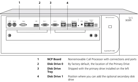
The SuperStack 3 NBX Call Processor (Figure 1) contains the system power supplies, cooling fans, and one disk drive. Optionally, you can add a second “mirrored” disk drive. (Disk mirroring is described in the NBX Administrator’s Guide in the NBX NetSet™ utility, on the NBX Resource Pack CD, or on the 3Com Partner Access web site.)
The Call Processor manages call traffic, voice mail, and the Automated Attendant. It can be licensed for up to 1500 devices. See “System
Configuration Guidelines” on page 47 for more information on the total
number of supported devices.
A SuperStack 3 NBX system is available in these base models:
■ With a single power supply and licensed for 250 devices
■ With redundant power supplies and licensed for 250 devices
CAUTION:Each of the two power supply units in the redundant model
has its own overcurrent protection device. That is, the overcurrent device for one power supply does not protect the second power supply. You must connect two AC power cords to the unit to power both of the power supplies.
A SuperStack 3 NBX system includes these features:
■ Supports the Telephony Application Programming Interface (TAPI) 2.X for Computer Telephony Integration (CTI) applications
■ Includes a web server to support the NBX NetSet administration utility
■ Includes an Internet Message Access Protocol (IMAP4) message server for integration of voice mail and e-mail
The SuperStack 3 NBX Call Processor has these connectors and LEDs, shown in Figure 1:
■ VOL — This adjusting screw controls the volume of Music On Hold.
■ MOH — This mini-jack (mono or stereo) accepts music-on-hold audio from the line output of a CD player, tape player, or other music source.
SuperStack 3 NBX Core Components 23
■ EXTERNAL ALERT —Reserved for future use.
■ Status Lights (LEDs) — Status lights indicate power, initialization, system status, and drive activity. See Figure 30 on page 51 for details.
Figure 1 Front Panel of the SuperStack 3 NBX Call Processor
For installation instructions, see Chapter 2.
SuperStack 3 NBXR
Mouse
KYBD Video USB Com 1 Com 2 Ethernet 1 Ethernet 2 MOH Paging
External Alert V
o l
NBX Call Processor
1 2 3 4
1 NCP Board Nonremovable Call Processor with connections and ports 2 Disk Drive 0 By factory default, the location of the Primary Drive 3 Disk Drive
Tray
Shipped with the primary drive installed on the left
24 CHAPTER 1: INTRODUCTION
SuperStack 3 NBX Gateway Chassis
The NBX Gateway Chassis (1 in Figure 2) contains four universal card slots. As shipped from the factory, the top three have faceplates and the fourth is left open. For installation instructions, see Chapter 2.
Figure 2 SuperStack 3 NBX Gateway Chassis (Front)
A single SuperStack 3 NBX Call Processor can support up to 25 NBX Gateway Chassis.
Use the upper 10/100 uplink port on each Gateway Chassis (shown at the top of the bracket labeled 2) to connect to the LAN. The lower port is normally inactive and becomes active only if the upper port experiences a link failure.
You must use straight-through Ethernet cable connections; you cannot use MDI/MDIX connections.
Power Partition Link/Activity Activity
10M Shared
10/100M Switched
10/100M Switched
10M Link 100M Link
3C10200 NBX Gateway Chassis
Activity 10M Link 100M Link
1 2 3
1 4-slot chassis Removable faceplates installed 2 10/100 Mbps switched Ethernet
connection
Two redundant uplink ports
3 10 Mbps shared Ethernet connection
NBX 100 Core Components 25
Redundant Power Supply
You can attach a redundant power supply to the RPS connector on the back of the NBX Gateway Chassis. Table 4 describes the items that you must purchase, assemble, and connect to the chassis. See your 3Com NBX Voice-Authorized Partner for purchasing details.
CAUTION:If you are using the 3Com SuperStack II ARPS (Advanced
Redundant Power Source) as a backup power supply for the NBX
Gateway Chassis, you can have no more than 2 Analog Terminal Cards of Models 3C10117, 3C10117A, or 3C10117B-INT per Gateway Chassis. This restriction does not apply to the 3C10117C Analog Terminal Card.
To connect the redundant power supply to the NBX Gateway Chassis:
1 Assemble the redundant power supply according to the instructions in the SuperStack II ARPS documentation.
2 Attach the “Y” cable to the RPS connector on the back of the NBX Gateway Chassis.
3 Connect the SuperStack II ARPS chassis to a source of AC power.
NBX 100 Core
Components
The heart of the NBX 100 Communications System is the Network Call Processor card. It and other removable cards sit in the 6-Slot Chassis.
NBX 100 6-Slot Chassis
The NBX 100 6-Slot Chassis, shown in Figure 3, holds the system power supply, disk drive, cooling fans, and removable cards, including the NBX 100 Call Processor.
All controls and connections are on the front of the chassis. The chassis fits into a standard 19-inch equipment rack, or it can be wall-mounted or placed on a table.
Table 4 Items in the Redundant Power Supply
Order Number Description Quantity
3C16071B SuperStack II ARPS Chassis 1
3C16074A Type 2A, 100W Power Module (NLP100-9640) 2
26 CHAPTER 1: INTRODUCTION
An NBX 100 system can have one or more chassis. The number depends on how many external telephone lines the system must support and the equipment that you choose for attaching telephones. Additional chassis must not contain an NBX Call Processor card.
Figure 3 NBX 100 Chassis with Call Processor and Cards
Up to six cards slide into the front of the chassis. An internal backplane connects the cards to each other.
The top slot has no access to the backplane. Always cover the top slot with a blank faceplate.
The Network Call Processor, interface cards, and devices are described later in this chapter.
For installation instructions, see Chapter 2.
NBX 100 O L V S 3 S 2 S 1
MOH PAGINGEXT. ALERT 10BT UPLINK COM 1 COM 2 MDI-X
1 2 3 4
1 2 3 4 PFT
1 2 3 4
1 2 3 4 PFT
1 2 3 4
1 2 3 4 PFT
PWR
1 1 2 3 4 5 6 7
8 8
3C10110D 3Com NBX Call Processor
3C10370 3Com NBX Uplink Card
3C10114C 3Com NBX Analog Line Card
3C10114C 3Com NBX Analog Line Card
3C10114C 3Com NBX Analog Line Card
10BT UPLINK MDI-X
3C10116C 3Com NBX Digital Line Card
NBX 100 Core Components 27
NBX 100 Call Processor
The top active slot in the primary NBX 100 chassis holds the NBX 100 Call Processor. The NBX 100 Call Processor:
■ Manages call traffic, voice mail, and the Automated Attendant
■ Supports the Telephony Application Programming Interface (TAPI) 2.X for Computer Telephony Integration (CTI) applications
■ Includes an Internet Messaging Access Protocol 4 (IMAP4) message server for integration of voice mail and e-mail and a web server to support web-based system administration
■ Supports all NBX line cards
■ Supports up to 200 devices. See “System Configuration Guidelines”
on page 47 for the rules about supported devices.
There are two versions of the NBX 100 Call Processor, shown in Figure 4
and Figure 5.
Figure 4 NBX 100 Call Processor (3C10110C)
Figure 5 NBX 100 Call Processor (3C10110D)
The difference between the 3C1011C and the 3C1011D is that the 3C10110C Network Call Processor includes a BNC connector for uplink connections.
The NBX 100 Call Processor has these status lights and connectors:
■ StatusLights — The three status lights (S1, S2, and S3) indicate:
S1 and S2 — Indicate operating system status.
■ If S1 and S2 are both flashing (approximately 2 flashes per second), the hardware is initializing.
■ If S1 is on and S2 is off, the operating system has started successfully. O L V S 3 S 2 S 1
MOH PAGING EXT. ALERT 10BT UPLINK COM 1 COM 2
BNC 10B2 MDI-X
3C10110C 3Com NBX Call Processor
O L V S 3 S 2 S 1
MOH PAGING EXT. ALERT 10BT UPLINK COM 1 COM 2
28 CHAPTER 1: INTRODUCTION
■ If S1 and S2 are both on, the operating system software has not started successfully.
■ If S1 and S2 flash in an alternating pattern, a file system check is in progress, possibly due to an improper shutdown, and the boot process will take longer than normal.
S3 — Indicates the status of music on hold (MOH).
■ If S3 is flashing (approximately 2 flashes per second), the music on hold processor is initializing. If this flashing continues for more than 2 minutes, the processor has not started successfully.
■ If S3 is on, the MOH processor has started successfully.
■ If S3 is flashing slowly (approximately 1 second on and 1 second off), the MOH processor has started successfully, but no music source is connected.
■ VOL-MOH — This mini-jack (mono or stereo) accepts Music-On-Hold audio from a CD player, tape player, or other music source. The adjusting screw next to the jack controls the volume.
■ PAGING — This RJ-11 connector provides an audio output or a dry contact switch connection for use with a public address system.
■ EXT ALERT — This RJ-11 connector is reserved for future use.
■ 10BT UPLINK — This connector provides means to connect to an external Ethernet switch or hub.
The 3C10110C Network Call Processor includes a BNC connector for uplink connections. The BNC and RJ-45 uplink connectors are alternative connections for a single port. They cannot be used simultaneously.
If you use the Uplink connector, be sure to program the switch or router on the other end for 10BASE-T 10 MB operation.
■ COM1 — The COM1 connector provides a DTE (Data Terminal Exchange) connection for use with a VT100-compatible control terminal. This connection provides command line access to the Call Processor’s operating system and diagnostic commands.
Overview of NBX Cards and Devices 29
Overview of NBX
Cards and Devices
This section lists all of the NBX devices that can be used with either the SuperStack 3 NBX or the NBX 100 system. Not all cards may be available in every region.
Before you install any Analog Line Cards or Digital Line Cards, you may want to configure the Dial Prefix settings. For information on this topic, see “Dial Prefix Settings” in Chapter 2 in the NBX Administrator’s Guide or the NBX NetSet Help at Dial Plan > Operations > Dial Prefix Settings.
Analog Line Card The NBX Analog Line Card connects up to four analog telephone lines to the NBX system. The SuperStack 3 NBX system can support up to 180 line cards (720 CO telephone lines) using multiple NBX Gateway chassis. The NBX 100 system can support up to 25 line cards (100 CO telephone lines) using multiple NBX 100 chassis.
Figure 6 NBX Analog Line Card (3C10114)
Figure 7 NBX Analog Line Card (3C10114C)
Functionally, 3C10114 and 3C10114C are identical. However, 3C10114C uses some different internal components so that 3C10114C requires NBX software release R4.1 or higher.
Each Analog Line Card contains the following lights and connectors:
■ Status Lights (1 through 4) — Each light shows the status of the associated line.
Initialization (prior to Release R4.1):
■ All four lights flash in unison – Hardware is initializing.
■ A light flashes on twice, off for 2 seconds – Associated port has been initialized successfully.
3C10114 3Com NBX Analog Line Card
CONSOLE
2 3 4
PFT 1
1 2 3 4
3C10114C 3Com NBX Analog Line Card LS
CONSOLE
2 3 4
PFT 1
30 CHAPTER 1: INTRODUCTION
Initialization (Release R4.1 and higher):
■ Fast steady blink – Waiting for software download.
■ Solid on – Software has been downloaded. The flash memory on the board is being loaded.
■ Slow, non-symmetric blinking pattern – Waiting for the completion of the binding process to the call processor.
Operation:
■ Off for 9 to 10 seconds, on briefly – Idle, the line is not in use.
■ On for 9 to 10 seconds, off briefly – A telephone call is connected on this port.
■ Console Connector — This DB-9 connector provides an RS-232 (DCE) TTY terminal connection for maintenance access.
T1 Digital Line Card The T1 Digital Line Card is an optional card that lets you connect a T1 line to the NBX system. The SuperStack 3 NBX system can accommodate up to 30 T1 Digital Line Cards (720 channels) if they are configured for DS1 operation, and 31 T1 Digital Line Cards (713 channels) if they are configured for ISDN PRI operation. The NBX 100 system can
accommodate up to 3 T1 Digital Line Cards (72 channels if the cards are configured for DS1 operation or 69 channels if the cards are configured for ISDN PRI operation), if you connect them using MDI-X ports. If you connect a T1 Digital Line Card using the NBX 100 system backplane, the system can accommodate only one card.
All digital line cards require NBX system software Release R2.6 or higher. The 3C10116D T1 Digital Line Card requires NBX system software Release R4.3 or higher.
You must have an external Channel Service Unit (CSU) when using the 3C10116CT1 Digital Line Card. 3C10116D includes an onboard CSU. The 3C10116D can provide CSU performance statistics, supports loopback testing, and can be configured as a remote device that communicates with its NCP over a routed network.
Overview of NBX Cards and Devices 31
ISDN PRI services require specific circuit provisioning, which you must obtain before you can use the T1 card in PRI mode. See Appendix B for more information.
Figure 8 T1 Digital Line Card (3C10116C)
Figure 9 T1 Digital Line Card (3C10116D)
The 3C10116C T1 Digital Line Card has the following lights and
connectors:
■ T1 — This RJ-48C connector makes a patch cord connection to a T1 interface (CSU/DSU).
■ Status Lights — These lights indicate the status of the card’s signaling, synchronization, and loop back test.
■ CF — On indicates a Carrier Failure. The T1 card is not receiving carrier signals from the far end of the T1 line.
■ RA — On indicates a Remote Alarm. The far (remote) end of the T1 line is not receiving appropriate signaling from the T1 board.
■ LB — On indicates that loop-back testing is in progress.
■ Nominal — On indicates ready to send and receive information.
■ 10BASE-T Uplink—This RJ-45 Ethernet connector connects the T1 card to an external LAN hub or switch. You can use this connector to isolate T1 traffic. If the T1 Digital Line Card is used in an NBX Gateway Chassis, you do not need to use this connector because the NBX Gateway chassis is connected to the LAN.
If you use the Uplink connector, be sure to program the switch or router on the other end for 10BASE-T 10 MB operation.
■ Console — This DB-9 connector provides an RS-232 (DCE) TTY terminal connection for maintenance access.
10BT UPLINK
MDI-X
3C10116C 3Com NBX Digital Line Card
CONSOLE CF
RA
32 CHAPTER 1: INTRODUCTION
The 3C10116D T1 Digital Line Card has the following lights and connectors:
■ T1 — This RJ-48C connector makes a patch cord connection to a T1 interface.
■ Status Lights — These lights indicate the status of the T1 card’s signaling, synchronization, and loop back test.
■ CO — Central Office:
Amber — Alarm condition at the remote end or the CO is not connected or available.
Green — No alarm condition.
■ POST — Power On Self Test
Off — POST test is running. The test runs approximately 5-seconds after you apply power to the board. After 5-seconds, Off indicates the POST test failed.
Green — POST test completed successfully.
■ DCH — D channel status of an ISDN PRI connection
Off — No T1 or T1 PRI line is attached or that the card does not need a D channel, such as when the card is running T1-robbed-bit (CAS).
Green — Card is configured for ISDN PRI operation and an active PRI connection has been established.
Amber — The D channel has not yet been established. It can take several seconds after the card has completed its power up tests for the card to establish a connection with the PRI trunk. If the DCH light goes to amber after the connection has been established, it can mean that an active control channel connection through the PRI line has been lost.
■ DNLD — Download
Flash — The card is downloading software from the NBX Network Call Processor.
Green — The download is complete or the Power-On-Self-Test (POST) is running.
Amber — The download was interrupted before it completed.
Overview of NBX Cards and Devices 33
network path, the download can take a few minutes. If the DNLD light remains amber, it can indicate a severely congested network or a hardware problem with the T1 card.
■ CALL — Call audio traffic
Off — No audio traffic on the T1 link.
Flashing — Audio traffic is present.
■ CARD — Card Software Status
Green — The card has finished downloading software from the NCP and all software processes have started successfully.
Amber — A problem with one or more of the software processes running on the card. The card automatically reboots itself if it detects a problem with any of its software processes.
■ DSP — Reserved for future use
■ NCP — Network Call Processor
Amber — The card is trying to establish contact with an NCP.
Green — The card has established contact with an NCP.
■ LNK — Ethernet link.
Green — The 10/100 Uplink port is connected to a 10Mb or to a 10/100 Mb hub or switch.
Red — The 10/100 Uplink port is connected to a 100 Mb hub or switch.
Off — There is no connection to the 10/100 Uplink port.
■ ACT— Ethernet activity.
Rapid blink — Data is passing into or out of the T1 card through the 10/100 Uplink port.
■ 10/100 Uplink—This RJ-45 Ethernet connector connects the T1 card to an external LAN hub or switch. You can use this connector to isolate T1 traffic. If the T1 Digital Line Card is used in an NBX Gateway Chassis, you do not need to use this connector because the NBX Gateway chassis is connected to the LAN.
■ Console — This DB-9 connector provides an RS-232 (DCE) TTY terminal connection for maintenance access.
34 CHAPTER 1: INTRODUCTION
E1 Digital Line Card The E1 Digital Line Card, used outside of North America, provides E1 connectivity using the ISDN PRI protocol. It carries data at a rate of 2.048 Mbps and can carry 32 channels, each with 64 Kbps. Thirty of these channels are available for calls. Like the T1 ISDN PRI Card, the E1 PRI Card supports PRI software features such as DID.
The SuperStack 3 NBX system can accommodate up to 24 E1 Digital Line Cards (720 channels). The NBX 100 system can accommodate up to 3 E1 Digital Line Cards (90 channels). If you connect an E1 Digital Line Card using the NBX 100 system backplane, the system can accommodate only one card.
3C10165D includes an onboard CSU. The 3C10165D can provide CSU performance statistics, can be enabled for loopback testing, and can be configured as a remote device that communicates with its NCP over a routed network.
ISDN PRI services require specific circuit provisioning, which you must obtain before using this card. See Appendix B for more information. for more information.
Figure 10 E1 Digital Line Card (3C10165C)
Figure 11 E1 Digital Line Card (3C10165D)
Each 3C10165C E1 card has the following lights and connectors:
■ E1 — This RJ-48C connector makes a connection to an ISDN interface channel service unit/data service unit (CSU/DSU).
■ Status Lights — These lights indicate the status of the card’s signaling, synchronization, and loop back test.
Overview of NBX Cards and Devices 35
■ RA — On indicates a Remote Alarm. The far end of the E1 line is not receiving appropriate signaling from the E1 board.
■ LB — On indicates that loop-back testing is going on.
■ Nominal — On indicates ready to send and receive information.
■ 10BASE-T Uplink MDI—This RJ-45 Ethernet connector connects the card to an external LAN hub or switch. If the E1 Digital Line Card is used in an NBX Gateway Chassis, you do not need to use this
connector because the NBX Gateway chassis is connected to the LAN.
If you use the Uplink connection, be sure to program the switch or router at the other end for 10BASE-T 10 MB operation.
■ Console—This DB-9 connector provides an RS-232 (DCE) TTY terminal connection for maintenance access.
Each 3C10165D E1 Digital Line Card has the following lights and connectors:
■ E1 — This RJ-48C connector makes a patch cord connection to a E1 interface.
■ Status Lights — These lights indicate the status of the card’s signaling, synchronization, and loop back test.
■ CO — Central Office:
Amber — Alarm condition at the remote end or the CO is not connected or available.
Green — No alarm condition.
■ POST — Power On Self Test:
Off — POST test is running. The test runs approximately 5-seconds after you apply power to the board. After 5-seconds, Off indicates the POST test failed.
Green — POST test completed successfully.
■ DCH — D channel status of an ISDN PRI connection
Off — No E1 or E1 PRI line is attached.
Green — Card is configured for ISDN PRI operation and an active PRI connection has been established.
36 CHAPTER 1: INTRODUCTION
light goes to amber after the connection has been established, it can mean that an active control channel connection through the PRI line has been lost.
■ DNLD — Download
Flash — The card is downloading software from the NBX Network Call Processor.
Green — The download is complete or the Power-On-Self-Test (POST) is running.
Amber — The download was interrupted before it completed.
On a LAN, the download process completes quickly. If the download from NCP to digital line card must travel a routed network path, the download may take a few minutes. If the DNLD light remains amber, it can indicate a severely congested network or a hardware problem with the card.
■ CALL — Call audio traffic
Off — No audio traffic on the T1 link.
Flashing — Audio traffic is present.
■ CARD — Card Software Status.
Green — The card has finished downloading software from the NCP and all software processes have started successfully.
Amber — A problem with one or more of the software processes running on the card. The card automatically reboots itself if it detects a problem with any of its software processes.
■ DSP — Reserved for future use.
■ NCP — Network Call Processor communications status.
Amber — The card is trying to establish contact with an NCP.
Green — The card has established contact with an NCP.
■ LNK — Ethernet link status.
Green — The 10/100 Uplink port is connected to a 10Mb or to a 10/100 Mb hub or switch.
Red — The 10/100 Uplink port is connected to a 100 Mb hub or switch.
Off — There is no connection to the 10/100 Uplink port.
Overview of NBX Cards and Devices 37
Rapid blink — Data is passing into or out of the card through the 10/100 Uplink port.
■ 10/100 Uplink—This RJ-45 Ethernet connector connects the E1 card to an external LAN hub or switch. You can use this connector to isolate E1 traffic. If the E1 Digital Line Card is used in an NBX Gateway Chassis, you do not need to use this connector because the NBX Gateway chassis is connected to the LAN.
■ Console — This DB-9 connector provides an RS-232 (DCE) TTY terminal connection for maintenance access.
If you require an alternative (bare wire-end) cable to use with the ISDN PRI Digital Line Card, contact your 3Com NBX Voice-Authorized Partner.
CAUTION:This equipment does not operate when the main power fails.
BRI-ST Digital Line Card
The ISDN BRI-ST (Basic Rate Interface) Digital Line Card (Figure 12) has four separate ports, each of which accommodates two B channels and one D channel. Each B channel carries user data at 64 Kbps and the D channel operates at 16 Kbps. If the two B channels are bonded, the transmission rate is 128 Kbps.
Figure 12 BRI-ST Digital Line Card (3C10164C)
CAUTION:The BRI-ST Digital Line Cards are not approved for use in the
United States or Canada.
■ Status Lights — Each port has three status lights (listed top to bottom):
■ D — Lights when this signaling channel is active.
■ B1 — Lights when this data channel is active (a call is in progress).
■ B2 — Lights when this data channel is active (a call is in progress).
■ Console—This DB-9 connector provides an RS-232 (DCE) TTY terminal connection for maintenance access.
CAUTION:This equipment does not operate when the main power fails.
3C10164C 3Com NBX Quad BRI-S/T Card
CONSOLE
D B1 B2
1 2 3 4
D B1 B2
D B1 B2 D
38 CHAPTER 1: INTRODUCTION
10BASE-T Uplink Card The 10BASE-T Uplink Card provides eight 10BASE-T Ethernet ports to connect 3Com Telephones (or other 10BASE-T devices) to the LAN. The Uplink Card (3C10370) replaces the 10BASE-T Hub Card (3C10115).
Figure 13 NBX Uplink Card (3C10370)
The NBX 10BASE-T Uplink Card contains the following status lights and connectors:
■ Status Lights (PWR and 1 through 8) — These lights indicate the status of power to the hub and the status of the 10BASE-T ports.
■ Ethernet Hub Ports (8) — These RJ-45 MDI-X ports connect devices to the LAN.
Analog Terminal Card Each Analog Terminal Card allows up to four analog (2500-series
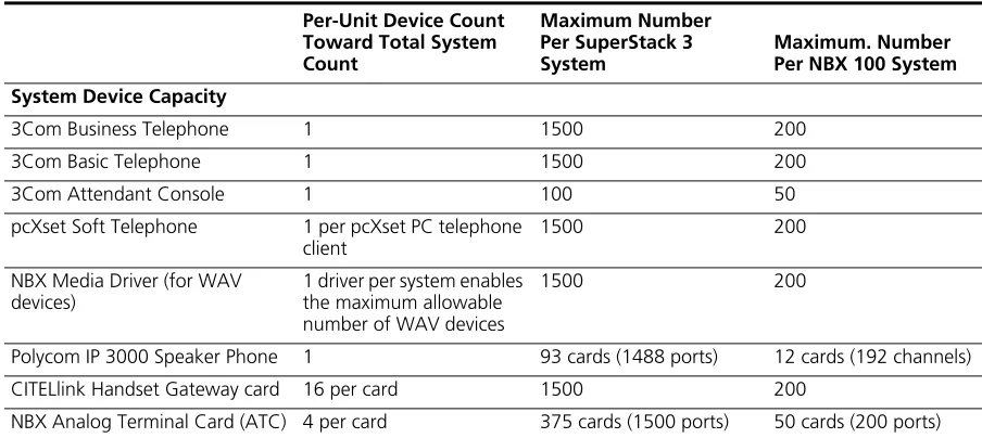
compliant) telephones, cordless telephones, and Group-3 fax machines to operate with NBX systems. The SuperStack 3 NBX system supports up to 375 Analog Terminal Cards, for a total of 1500 devices. The NBX 100 system supports up to 50 Analog Terminal Cards, for a total of 200 devices.
However, see “System Configuration Guidelines” on page 47.
CAUTION:If you are using the 3Com SuperStack II ARPS (Advanced
Redundant Power Source) as a backup power supply for the NBX
Gateway Chassis, you can have no more than 2 Analog Terminal Cards of Models 3C10117, 3C10117A, or 3C10117B-INT per Gateway Chassis. This restriction does not apply to the 3C10117C Analog Terminal Card.
When an Analog Terminal Card senses that a port is being used for fax transmission, it switches that port to reliable mode. Unlike normal voice transfers, which drop packets when they encounter congestion, reliable mode transmissions take as much time as needed to ensure that there are no lost packets. However, reliable mode also uses twice the bandwidth.
PWR
1
1 2 3 4 5 6 7
8 8
Overview of NBX Cards and Devices 39
Figure 14 NBX Analog Terminal Card (3C10117B-INT)
Figure 15 NBX Analog Terminal Card (3C10117C)
Each Analog Terminal Card has the following lights and connectors:
■ Analog Connectors (1 through 4) — Four RJ11connectors enable you to connect analog devices to the NBX system.
■ Status Lights (1 through 4) — Each light indicates the status of the associated port.
Initialization:
■ Fast steady blink – Waiting for software download.
■ Solid on – Software has been downloaded. The flash memory on the board is being loaded.
■ Slow, non-symmetric blinking pattern – Waiting for the completion of the binding process to the call processor.
Operation:
■ Off for 9 to 10 seconds, on briefly – Idle, telephone is on hook.
■ On for 9 to 10 seconds, off briefly – Idle, telephone is off hook.
■ Console Connector — This DB-9 connector provides an RS-232 (DCE) TTY terminal connection for maintenance access.
3C10117B-INT 3Com NBX Analog Terminal Card
CONSOLE
2 3 4
1
1 2 3 4
NOT FOR TELECOM USE
3C10117C 3Com NBX Analog Terminal Card
CONSOLE
2 3 4
1
1 2 3 4
40 CHAPTER 1: INTRODUCTION
Analog Terminal Adapters
The single-port Analog Terminal Adapter (ATA) is a desktop box that connects an analog telephone or fax machine to an NBX system.
Figure 16 Analog Terminal Adapter (3C10400) — Front View
Figure 17 Analog Terminal Adapter (3C10400) — Rear View
The Analog Terminal Adapter (3C10400) has the same functions as the 3C10120B plus these features:
■ Power Over Ethernet (PoE) — The 3C10400 ATA can accept power
over the Ethernet cable. It meets the IEEE 802.3af standard for Power over Ethernet. It can also accept power from an AC power adapter plugged into a wall socket.
■ Diagnostic Port — The 3C10400 ATA has an RS232 DB9 connector
to which you can connect a serial cable. Using a terminal emulation program such as Hyperterm, you can access the ATA and use diagnostic and troubleshooting commands.
Only qualified 3Com service personnel should use the serial diagnostic port.
The Analog Terminal Adapter (3C10400) has these lights and connectors:
■ Power Light — The light below the icon for power indicates that the ATA is receiving power.
■ POTS Status Lights (S1, S2, S3) — The POTS (Plain Old Telephone Service) status lights indicate the status of the Analog Port. S3 turns on when the analog telephone is in use. S2 blinks briefly every ten seconds when an analog telephone is connected to the ATA. If no
NBX Analog Terminal Adapter
POTS Status
LAN Link PC Link Power
POTS LAN PC
IOIO1
Overview of NBX Cards and Devices 41
analog telephone is connected, S2 is always off. S1 is reserved for future use.
■ PC Link Light — Indicates that there is an external network device connected to the ATA.
■ LAN Link Light — Indicates that the ATA is connected to the network.
■ 10101 — Serial port for diagnostics.
■ POTS — A connection for an analog telephone or fax machine.
■ PC — Provides a connection for a network device such as a 3Com telephone.
■ LAN — Provides a connection to the network.
Figure 18 Analog Terminal Adapter (3C10120B) — Front View
Figure 19 Analog Terminal Adapter (3C10120B) — Rear View
The Analog Terminal Adapter (3C10120B) has these lights and connectors:
■ Power Light —The light below the icon for power indicates that the ATA is receiving power.
■ Analog Port Status Lights (S1, S2, S3) — The lights below the icon for the analog telephone indicate the status of the Analog Port. S3 turns on when the analog telephone is in use. S2 blinks briefly every ten seconds when an analog telephone is connected to the ATA. If no analog telephone is connected, S2 is always off. S1 is reserved for future use.
■ Single Status Lights — The lights located below the icons for the power connector and the Ethernet ports indicate the status of the related port.
S1 S2 S3
42 CHAPTER 1: INTRODUCTION
■ Analog Port — A connection for an analog telephone or fax machine.
■ Hub Port — Provides a connection for a network device such as a 3Com telephone.
■ Network Port — Provides a connection to the network.
The Analog Terminal Adapter might require a telephone connector adapter for use outside of North America. Contact your 3Com NBX Voice-Authorized Partner for country-specific requirements.
3Com Telephones 3Com Telephones provide the familiar features of a business telephone and extra features such as one-touch access to voice mail. 3Com
Telephones operate at either 10 Mbps or 100 Mbps and contain a 10/100 Mbps switch with two ports. One port connects the telephone to the LAN and the other port can be used to connect a computer to the LAN. 3Com Telephones that have the IR designation in their part numbers, such as the 3C10228IRB and 3C10228IRPE, have an infrared port that allows the user to exchange data between a Personal Digital Assistant device and the telephone.
These 3Com devices require a license:
■ 3102 Business Telephone
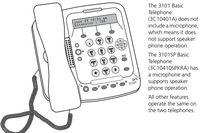
■ 3101 or 3101SP Basic Telephones
■ 3105 Attendant Console