Pool boiling heat transfer for surfaces with microchannels of
variable depth
Robert Pastuszko1*, Milena Bedla-Pawlusek2 and Robert Kaniowski1
1Kielce University of Technology, Faculty of Mechatronics and Mechanical Engineering, al. 1000-lecia Państwa Polskiego 7, PL-25-314 Kielce, Poland
2Holy Cross Cancer Center, Technical Department, Artwińskiego Street 3, PL-25-734 Kielce
Abstract. Experimental investigations of pool boiling heat transfer on microchannels of variable depth were conducted. The experiments were carried out for water and ethanol at atmospheric pressure. Microchannels of variable depth from 0.2 to 2.8 mm and width 0.5 mm were uniformly spaced on base surface with pitch of 1 mm. The comparison of heat transfer coefficients for surfaces with variable and constant depth of microchannels was made. At the low and medium heat fluxes structures with constant microchannel depth showed the best boiling heat transfer performance. EX-FH20 (Casio) camera was used to record the images of the entire surface of the specimen. The bubble growth mechanism on the enhanced surface was different from that of plain surface. Visualization investigations were aimed at identifying nucleation sites and determining the bubble growth cycle. Vapor bubbles generate in microchannel spaces, from where they move towards the fin tips, then grow and depart.
1 Introduction
The paper deals with experimental investigations of boiling heat transfer on a system of parallel horizontal channels. This structures can be applied for cooling miniature integrated devices, such as microprocessors,
by a direct or indirect method (as a thermosyphon or tube evaporator), substituting forced convection (traditional fan). An overview of the surfaces with microchannels and the heat transfer coefficients obtained are presented in Table 1.
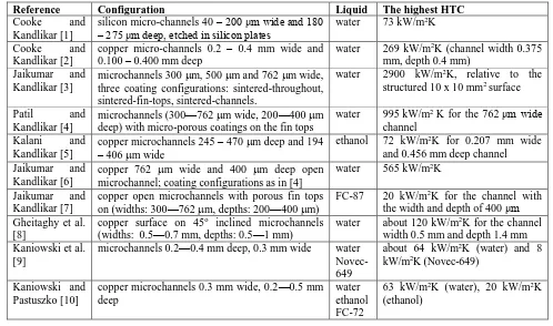
Table 1. Types of open microchannels for pool boiling enhanced heat transfer
Reference Configuration Liquid The highest HTC
Cooke and Kandlikar [1]
silicon micro-channels 40 – 200 μm wide and 180 – 275 μm deep, etched in silicon plates
water 73 kW/m2K
Cooke and Kandlikar [2]
copper micro-channels 0.2 – 0.4 mm wide and 0.100 – 0.400 mm deep
water 269 kW/m2K (channel width 0.375
mm, depth 0.4 mm) Jaikumar and
Kandlikar [3]
microchannels 300 m, 500 m and 762 m wide, three coating configurations: sintered-throughout, sintered-fin-tops, sintered-channels.
water 2900 kW/m2K, relative to the
structured 10 x 10 mm2 surface
Patil and Kandlikar [4]
microchannels (300—762 m wide, 200—400 m deep) with micro-porous coatings on the fin tops
water 995 kW/m2 K for the 762 μm wide
channel Kalani and
Kandlikar [5]
copper microchannels 245 – 470 m deep and 194 – 406 m wide
ethanol 72 kW/m2K for 0.207 mm wide
and 0.456 mm deep channel Jaikumar and
Kandlikar [6]
copper 762 m wide and 400 m deep open microchannel; coating configurations as in [4]
water 565 kW/m2K
Jaikumar and Kandlikar [7]
copper open microchannels with porous fin tops on (widths: 300—762 m, depths: 200—400 m)
FC-87 20 kW/m2K for the channel with
the width and depth of 400 μm Gheitaghy et al.
[8]
copper surface on 45o inclined microchannels
(widths: 0.5—0.7 mm, depths: 0.5—1 mm)
water about 120 kW/m2K for the channel
width 0.5 mm and depth 1.4 mm Kaniowski et al.
[9]
microchannels 0.2—0.4 mm deep, 0.3 mm wide water Novec-649
about 64 kW/m2K (water) and 8
kW/m2K (Novec-649)
Kaniowski and Pastuszko [10]
copper microchannels 0.3 mm wide, 0.2—0.5 mm deep
water ethanol FC-72
63 kW/m2K (water), 20 kW/m2K
Kaniowski and Pastuszko [11]
copper microchannels 0.3 mm wide, 0.2—0.5 mm deep
ethanol FC-72
exceeded 20 kW/m2K for ethanol
and 10 kW/m2K for FC-72
Kalani and Kandlikar [12]
copper open microchannels (widths: 194—406 m, depths: 245—470 m),16.7—101.3 kPa
ethanol about 65 kW/m2K for the channel
width 0.2 mm and depth 0.456 mm (at 101.3 kPa)
Rahman and McCarthy [13]
copper microchannel (characteristic lengths of 300μm to 3mm) with nanostructured coatings (characteristic lengths of 50 nm to 50μm)
water 461 kW/m2 K
Kwak et al. [14] copper microchannel with SiO2 layer (widths: 30
m, depths: 10—100 m) water about 60 kW/m
2K for the channel
width 30 m, depths 100 m Walunj and
Sathyabhama [15]
rectangular, parabolic and stepped microchannels on 10-mm diameter copper rod; channel widths: 250—800 μm; depth: 500 μm.
water about 16 kW/m2K
The objective of this article is comparison of surfaces with variable and constant depth microchannels with respect to boiling heat transfer enhancement, taking into account microchannels of 0.4 – 0.5 mm in wide.
2 Experimental setup
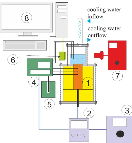
The diagram of the measurement stand for the determination of boiling curves is presented in Figure 1.
The main stand module (Fig. 2) consists of a vessel with four flat glass walls (2), filled with working fluid, and placed over the investigated sample (3). The sample was soldered to a 170 mm long cylindrical copper bar of 45 mm diameter. The cylinder diameter corresponded to the diagonal of the sample base. A 1000 W electric cartridge heater of 19 mm diameter and 130 mm long was installed into the bar. Before assembly the heater was coated with a special thermal paste to eliminate air spaces and decrease thermal resistance between the heater and cylinder material.
Fig. 1. Measurement system: 1 – main module, 2 – wattmeter,
3 – autotransformer, 4 – data logger , 5 – dry-well calibrator, 6 – high speed camera, 7 – lights, 8 – PC.
Type K (NiCr-NiAl) sheathed thermocouples of 0.5 mm in diameter were used for the measurements. They were placed as follows:
in the liquid – saturation temperature measurement (T1, T2),
under the sample – extrapolated to fin base temperature (T3, T4),
in the bar at 5, 10, 20 and 35 mm depth (Fig .3) – temperature gradient determination (T5, T6, T7, T8).
Fig. 2. Main module; 1 – top flange, 2 – glass vessel, 3 –
sample, 4 – teflon annular flange, 5 – insulation, 6 – condenser.
1
2
3
4
5
6
Fig. 3. Arrangement of thermocouples.
The heat flux was determined on the basis of the temperature gradient in the upper part of the heating cylinder, assuming one-dimensional heat conduction
8 8
T5-T 5-T T Cu
l T
q (1)
Temperature superheat (T) was related to micro-fin base. Due to the shift of the temperature measurement point, the superheat was calculated with the following dependence
sat Cu
bs T T
T T ql T
T
T
, 3 4 3
2
(2)
lT3,bs – means the distance between the microchannel
top and thermocouples under the sample (T3,T4). The estimated uncertainties were as follows:
low heat flux (2 kW/m2): heat flux ±35%, heat
transfer coefficient ±40%,
high heat flux (550 kW/m2): heat flux ±1.2%, heat
transfer coefficient ±2.2%.
The method of Kline and McClintock was used to determine uncertainty. The quoted heat fluxes referred to the fin bases. The heat transfer coefficient was expressed as:
T q
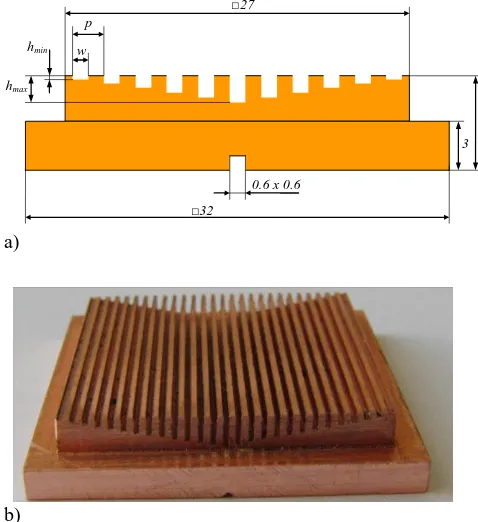
(3)3 Test surfaces
Original studies were conducted in order to plot boiling curves and perform visualisations on two types of structures (Figs. 4 and 5):
with open microchannels of constant depth – MC
with open microchannels of variable depth – MCV.The samples with microchannels were made of copper and had parallel grooves with a constant pitch, made with an end mill (CNC machining process). The
test section with a 27 x 27 mm2 boiling region consisted
of a 32 x 32 mm2 base square copper sample.
Table 2 compiles the surface codes and specifications according to Figs 4 and 5.
p
h w
0.6 x 0.6
3 5 □27
□32
a)
b)
Fig. 4. a) Dimension symbols of the surface MC, b) view of the
sample MC.
p
hmax
hmin w
0.6 x 0.6
3 6 □27
□32
a)
b)
Fig. 5. a) Dimension symbols of the surface MCV, b) view of
the sample MCV.
Table 2. MC/MCV surface codes and specifications.
Sample code w
mm
hmin
mm
hmax
mm
h
mm
p
mm
MC-0.4-0.5-0.8 0.4 0.5 0.5 0 0.8
MCV-0.5-0.2_2.8-1 0.5 0.2 2.8 0.2 1.0
T5
T6
T7
T8
10
5 5
20
4
Results
Two types of surfaces (MC and MCV) were examined to study the influence of the kind of extended surface on nucleate boiling heat transfer performance for two different liquids (water, ethanol).
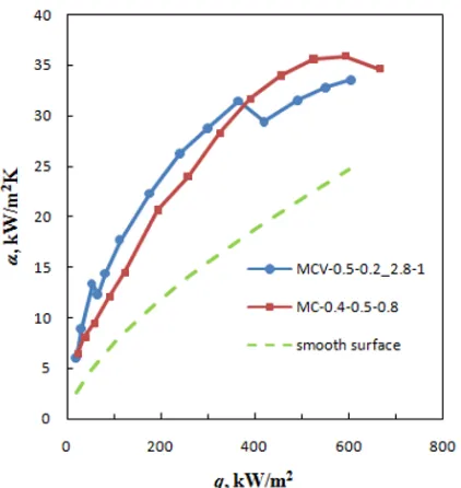
The effect of the microchannel depth and width for water is shown in Fig. 6. The best results, with low and medium heat fluxes (q < 350 kW/m2) were obtained for
microchannels with variable depth (MCV). For higher heat fluxes microchannels with constant depth (MC) shows about 10% higher heat transfer coefficients than surface MCV. Boiling heat transfer enhancement for MCV related to plain surface (α/α ps) is about 2 at heat fluxes 100 – 350 kW/m2.
With ethanol boiling, the performance of microchannels has proved especially good for the MC surface (Fig. 7). Boiling heat transfer enhancement related to plain surface(α/α ps) is 2 – 1.5 in the range q = 100 – 300 kW/m2. Compared with MC surface, MCV
surface gave lower heat transfer coefficients especially for higher heat fluxes (q > 300 kW/m2).
Fig. 6. Boiling curves for water, heat transfer coefficient vs.
heat flux.
The mechanism of bubble nucleation, growing and departing is shown in Figs 8 and 9. Vapor bubble generated in microchannel spaces between neighboring microfins in the corner at the microchannel base. It grew and moved towards the microfin tip. The second stage of growth was observed when the bubble adhered to the top of the microfin. Increasing volume of the bubble increased buoyancy force. The growing bubble departed from the microfin top.
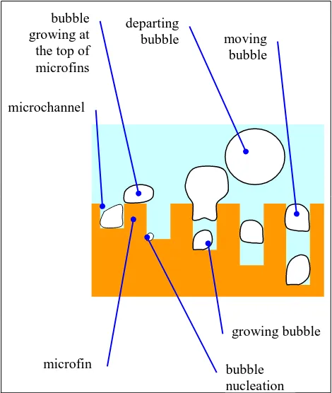
For microchannels of variable depth predicted boiling mechanism may be related to macroconvection with separate liquid-vapor pathways as well as with sustion-evaporation mode.
Figure 10 shows predicted boiling mechanism for microchannels with changing channels’ depth. Small
Fig. 7. Boiling curves for ethanol, heat transfer coefficient vs.
heat flux.
a) b)
c) d)
Fig. 8. Visualization observations of pool boiling of water on
the microchannel surface MC-0.5-0.2_2.8-1, q = 30 kW/m2, a)
d=0.6 mm, b) d = 0.9 mm, c) d = 1.4 mm, d) d = 2.1 mm.
a) b)
c) d)
e)
Fig. 9. Visualization observations of pool boiling of ethanol on
the microchannel surface MCV-0.5-0.2_2.8-1, q = 30 kW/m2, a) d = 0.25 mm, b) d = 0.5 mm, c) d =0.75 mm, d) d = 0.90 mm, e) d = 1.20 mm.
depth channels will contribute to the onset of nucleate boiling (ONB) at low superheating, but at medium heat flux heat transfer coefficient decreases after dry-out heat flux (DHF) is reached. Microchannels with greater depth improve the pool boiling performance at higher heat flux – they do not only provide an aditional surface for boiling heat transfer and nucleation, but they can prevent large bubbles from coalescing into a vapor blanket. This kind of vapor layer could cover the whole MC surface and ultimately dry out. Deep microchannels can eliminate this phenomenon, so that the critical heat flux (CHF) will have higher values.
Fig. 10. Mixed boiling mode in microchannels of variable
depth.
5
Conclusion
The following conclusions can be drawn from the experiments:
When boiling water on microchannels with constant (MC) and variable depth (MCV), similar heat transfer coefficients (HTC) were obtained. During the boiling of ethanol, higher HTC values occurred at the highest heat fluxes.
Visualization studies allowed the recognition of a two-stage bubble growing mechanism: initially at the bottom of the microchannel, and later at the top of the microfins that limit the microchannel. More exact conclusions can be drawn after testing a
larger number of samples with MC and MCV surfaces in the range of 0.2 mm and 0.6 mm mm.
Nomenclature
CHF – critical heat flux,
d – diameter, m, h – depth, m,
HTC – heat transfer coefficient,
l – distance between thermocouples, m,
MC – microchannel,
MCV – microchannel with variable depth,
p – pitch, m,
q – heat flux, kW/m2, T – temperature, K, w – width, m,
Greek symbols
– heat transfer coefficient, W/(m2K),
– thermal conductivity, W/(mK),
h
– change of depth, m,T
– difference of temperature, K,Subscripts
bs – base, Cu – copper, ps – plain surface, sat – saturation,
References
1. D. Cooke, S. G. Kandlikar, J. Heat Transfer 133
(2011)
2. D. Cooke, S. G. Kandlikar, Int. J. Heat and Mass Transfer 55 (2012)
3. A. Jaikumar, S. G. Kandlikar, Int. J. Heat and Mass Transfer 95 (2016)
4. Ch. M. Patil, S. G. Kandlikar, Int. J. Heat and Mass Transfer 79 (2014)
5. A. Kalani, S.G. Kandlikar, proc. ASME 10th Int. Conf. Nanochannels, Microchannels and Minichannels, Rio Grande, Puerto Rico (2012) 6. A. Jaikumar, S. Kandlikar, Int. J. Heat and Mass
Transfer 88 (2015)
7. A. Jaikumar, S. Kandlikar, App. Thermal Engineering 91 (2015)
8. A.M. Gheitaghy, A. Samimi, H. Saffari, App. Thermal Engineering 126 (2017)
9. R. Kaniowski, R. Pastuszko, Ł. Nowakowski, EPJ Web of Conferences 143, 02049 (2017)
10. R. Kaniowski, R. Pastuszko, EPJ Web of Conferences 180,02042 (2018)
11. R. Kaniowski, R. Pastuszko, EPJ Web of Conferences 180, 02041 (2018)
12. A. Kalani, S.G. Kandlikar, J. Heat Transfer. 135
(2013)
13. M.M. Rahman, M. McCarthy, J. Heat Transfer 139 (2017)
14. H. J. Kwak, J. H. Kim, B. Myung, M. H. Kim, D. E. Kim, Int. J. of Thermal Sciences 125 (2018)
15. A. Walunj, A. Sathyabhama, Appl. Therm. Eng. 128 (2018)
departing bubble
microfin bubble
nucleation growing bubble moving
bubble