R E S E A R C H
Open Access
Diversity and delay performance of max
link selection relay cooperation systems
over non-identical Nakagami-
m
fading
channels
Xiangdong Jia
1,2,3*, Meng Zhou
1, Xiaochao Dang
1, Longxiang Yang
2,3and Hongbo Zhu
2,3Abstract
The work focuses on the max link selection (MLS) schemes of buffer-aided relaying over the independent and non-identically distributed (i.ni.d) Nakagami-m fading channels in terms of outage probability, average packet delay, and improved diversity-delay trade-off schemes. By modeling the transition of buffer states as a Markov chain, we first obtain the outage probability and average packet delays for MLS schemes, which are given with closed-form expressions. The achieved results show that the i.ni.d fading channels impose severe loss in the diversity and coding gains of MLS schemes. Especially, when the disparity among the channel powers is very large, the diversity order provided by the MLS schemes is less than the ones provided by the traditional best relay selection (T-BRS) and max-max link selection (MMLS) schemes even if the buffers’ size is large enough. For the average packet delay of MLS schemes, our results show that they are impacted by the transmit power and the fading severity factors. In general, in the low transmit power, the average packet delays are varying with the transmit power. However, in the high transmit power, the average packet delays approach the stationary values. Besides of this, it is also achieved that the i.ni.d fading makes the average packet delays of MLS schemes at all relays are different. When the powers of relay-destination links are greater than the ones of source-relay links, the average packet delays can be reduced evidently. Motivated by the observations, a weight-based MLS (W-MLS) diversity-delay trade-off scheme is proposed. The proposed W-MLS diversity-delay trade-off schemes not only have the low packet delays at all relays but also provide enough diversity and coding gains over T-BRS and MMML, which can overcome the performance loss caused by non-identical distribution on MLS schemes.
Keywords: Cooperative relay, Buffers, Non-identical fading, Nakagami-m, Outage performance, Packet delay
1 Introduction
Recently, cooperative diversity has received much atten-tion from academia and industry due to its ability to in-crease the throughput, coverage, and reliability of wireless networks [1, 2]. It is based on the broadcast na-ture of wireless medium. In cooperative diversity sys-tems, each node can act as a relay and helps the other
nodes of the networks to forward their information to their respective destination nodes so that the spatial di-versity is exploited. The relay cooperation channels were first investigated by van der Meulen [3]. While the works [4–8] investigated the three-node relay channel, the work [9] considered the multi-relay cooperation ones, where the best relay selection scheme has been proposed (that also referred as traditional best relay selection (T-BRS)). All these works have proved that coopera-tive systems offer outstanding throughput gains over non-cooperative ones [10–13].
However, due to the practical half-duplex (HD) con-straint, in traditional protocols, the relays employ a * Correspondence:[email protected]
1
College of Computer Science and Engineering, Northwest Normal University, Lanzhou 730070, China
2Wireless Communication Key Lab of Jiangsu Province, Nanjing University of
Posts and Telecommunications, Nanjing 210003, China Full list of author information is available at the end of the article
prefixed schedule for transmission and reception, which is independent from the quality of the transmitting and receiving channels in a round of communications. The prefixed transmission and reception schedule limits the exploitation of achievable diversity degrees. Moreover, for multi-relay cooperation schemes, only the same relay node is selected for receiving data from source and for-warding data to destination in a round of communica-tions. This prefixed schedule and the selection of the same relay in a round of communications may lead significant performance degradation in wireless systems where the qualities of the transmitting and receiving channels significantly vary with time, since it may pre-vent the relays from exploiting the best transmitting and the best receiving channels. Clearly, the performance of the HD relaying systems could be improved if the above constrains are relaxed. For example, by relaxing the prefixed schedule constraint for data reception and transmission, the link with the highest quality could be always used in each time slot. Similarly, by relaxing the constraint of the same relay employed in a round of communications, the systems can always select the re-lays with the strongest source-relay (S-R) channel and the strongest relay-destination (R-D) channel for recep-tion and transmission, respectively. To achieve the ends, it is only possible if the relays are equipped with a buffer and can store data packets before retransmitting them later at a suitable time slot.
Early works of buffer-aided relaying systems can be founded in [14] and [15], where a three-node relaying system was considered and a data buffer was intro-duced at relay node. Due to the prefixed transmission and reception schedule abandoned, the results in [14] and [15] showed that the utilization of data buffer at relay can improve the throughout of relaying systems. The literature [16] focused on the multi-antenna re-laying system with buffer at relay and pointed out that if the numbers of antennas at source and destin-ation are equal or larger than the number of antennas at relay, the buffer-aided half-duplex systems can out-perform the ideal full-duplex ones. Motivated by the works [14] and [15], the buffer-aided relay systems have been investigated widely such as in [17–25]. Later, in [26] and [27] the idea of buffer-aided relay-ing was expanded to multiple relay systems, where the authors have proposed the max-max link selection (MMLS) protocol firstly. Specially, to exploit the quality of relay channels as possible, the MMLS schemes abandon the restriction of using the same relay for reception and transmission in a round of communications. Because the strongest links from both S-R and R-D group channels are always selected for data transmission, respectively, the MMLS scheme has significant coding gain over the traditional max-min
scheme [12]. However, the results in [26] and [27] show also that the diversity gain achieved by the max-max selection schemes is still the same as the one achieved by the T-BRS schemes owing to a prefixed transmission and reception schedule employed, such that the available diversity degree being not full exploited. Therefore, to overcome this prefixed sched-ule constraint and to improve the diversity gain of buffer-aided relay selection systems, in [28], the max-link selection (MLS) scheme has been proposed. In the MLS schemes, the constraint on the prefixed transmission and reception order is further relaxed so that, at any time, a best link is selected from all avail-able source-relay and relay-destination links. Depend-ing on whether one S-R or R-D link is selected, either source or relay transmits opportunistically a data packet to the corresponding destination. The MLS schemes incorporate the instantaneous quality of wireless links as well as the states of finite relay buffers (e.g., full, empty, neither full nor empty) and adapt the time slot allocation accordingly. It was achieved that when all relay channels obey independ-ent and idindepend-entically distributed (i.i.d) Rayleigh fading, the MLS schemes not only obtain coding gain over the T-BRS and MMLS schemes but also has higher diversity gain than the two schemes. The achievable diversity order approaches two times of the one of T-BRS and MMLS schemes in the ideal case where all channels experience i.i.d fading and the size of buffers grows to infinity. In [29], the buffer-aided amplify-and-forward (AF) MLS schemes have been considered over symmetric relaying channel. With the promising MLS protocol, in [30], a hybrid cooperative relaying policy was proposed. In [31], the buffer-aided multi-relay cognitive system has been investigated.
From the above literature review, it is clearly seen that the introducing of buffer at relay can signifi-cantly improve the performance of the traditional co-operation communication systems. Especially, under the extreme case where all relay channels experience the i.i.d fading, the MLS schemes are promising since the higher diversity and coding gains can be achieved over the MMLS and T-BRS schemes. However, all of the existing works about the MLS buffer-aided relay cooperation only focused on the i.i.d fading channels. For the more general scenarios where all relay chan-nels experience the independent and non-identically distributed (i.ni.d) fading, the corresponding perform-ance of the MLS schemes has not been achieved so far. However, in practical wireless implementation, due to the fact that all relays can locate at different positions and the bad wireless propagation, the S-R
have severe effect on the performance of the MLS schemes such as outage probability, symbol error rate, and average packet delay. Secondly, all of the existing works about the MLS schemes only consider Rayleigh fading scenario without Nakagami-m one. It is well known that Nakagami-m fading spans via the fading severity factor m, a wide range of fading scenarios that are typical in realistic wireless relay networks, which includes Rayleigh fading (m= 1) as special case. When the channels experience Nakagami-m fading, the performance of the MLS schemes is impacted by not only the channel variances but also the fading se-verity factors.
Therefore, motivated by the above literature review, in this work, the buffer-aided MLS schemes are inves-tigated over the i.ni.d Nakagami-m fading channels. The contributions of this work are summarized as follows.
(1) By modeling the transition of buffer states as a Markov Chain, we first obtain the state transition matrix and the stationary state probability vector as well as the closed-form expressions in terms of out-age probability and averout-age packet delays over the i.ni.d Nakagami-m fading channels. To the best of authors’ knowledge, this is new. The presented com-parison analysis shows clearly that when the relay channels experience the non-identical fading, the achievable diversity and coding gains by MLS schemes are suffered greatly from the disparity among the relay channel powers and the fading severity factors.
(2) For the average packet delays of MLS schemes, it is achieved that the average packet delays at all re-lays are the same entirely when the S-R and R-D links follow the i.i.d fading channels, respectively. More-over, the average packet delays are also independent from the transmit power and the channel fading se-verity factors. However, under the i.ni.d fading chan-nels, the average packet delays at all relays are different. This phenomenon yields that the MLS sys-tems are unstable. At the same time, it is also achieved that when the powers of S-R links are less than the ones of R-D links, the average packet delays can be reduced evidently.
(3) In order to reduce the average packet delays and to enhance the stability of the MLS systems but still obtain the enough diversity and coding gains, we fi-nally propose a weight-based MLS (W-MLS) diversity-delay trade-off scheme. By adjusting weight factor, it can be guaranteed that the equivalent signal-to-noise ratios (SNRs) of S-R links are less than the ones of
R-D links such that the novel W-MLS schemes achieve the satisfying trade-off between diversity and delay.
Note that, for the MLS scheme, the work [26] is very important and inspired our work. For comparison in this work, we also employ the framework in [26]. However, the evident advancement is performed in our work over the work [26]. Firstly, our work focuses on the i.ni.d Nakagami-m fading channels, while the work [26] con-sidered the i.i.d Rayleigh ones. Secondly, our work inves-tigates the impact of the i.ni.d fading channels on the diversity and coding gains as well as the average packet delay at relay. Finally, based on our derivations, we propose a weight-based MLS scheme, which can over-come the performance degradation caused by the i.ni.d fading.
Notation: In this work, we use boldface lower case letters to denote vectors and boldface capital letters to denote matrices. Omn is a m×n matrix with all
el-ements equal to zero, and I denotes the identity matrix. Moreover, (.)−1 and (.)T stand for matrix in-version and transpositions, respectively. Anm is the
(n,m)th entry of A. Pr(X) denotes the probability of event X. FX(.) and fX(.) are the cumulative distribu-tion funcdistribu-tion (CDF) and probability density funcdistribu-tion (PDF) of the random variable (RV) X, respectively. Γ(.) and ϒ(.,.) denote gamma function and incom-plete gamma function.
2 System model and MLS schemes
2.1 System model and assumptions
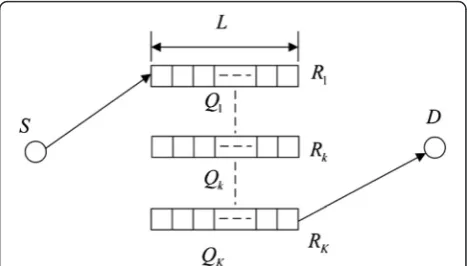
As shown in Fig. 1, we consider a buffer-aided relay-ing system, which consists of one source S, one des-tination D, K relays Rk, k∈{1,…,K}. Each relay node
Rk is equipped with a data buffer Qk of finite size L
(the number of buffer elements), and each buffer element can store one data packet of information bits. Note that, throughout this work, it is assumed that all buffers have the same size. Due to the severe fad-ing and showfad-ing, we omit the direct link between source S and destination D. All nodes work in FD mode, and there, they cannot transmit and receive
simultaneously. We also define Ψ(Qk) denoting the number of data packets in buffer Qk. We have 0≤Ψ(Qk)≤L.
We assume that hSRk denotes that channel coefficient
between the source S and the relay Rk and hRkD stands
for the one between the relayRk and the destinationD. The corresponding link gains are given byγSRk ¼jhSRkj
2
, γRkD¼jhRkDj
2. It is also assumed that all relay links are
reciprocal and experience the i.ni.d Nakagami-m fading. Therefore, the probability density function of the link gainsγSRk andγRkDis given by
fγ
Uð Þ ¼γ
1 ΓðmUÞ
mU
ωU
mU
γmU−1exp −mU
ωUγ
ð1Þ
where U∈ γSRk;γRkD
n o
, ωU and mU denote the
corre-sponding channel variance and fading severity factor. At each receiver, the received signals are affected by the circularly symmetric complex Gaussian additive noise with identical noise power N0. Without the loss of gen-erality, throughout this work, we take the noise power
N0= 1.
2.2 MLS schemes
In traditional best relay selection, the system perform-ance is limited since in a round of communications, the same relay node is selected for receiving data from source and transmitting data to destination in a prefixed transmission order. Namely, in the T-BRS, both the available link quality and the degree of di-versity freedom are not exploited effectively. Although the MMSL allows the different relays utilized for re-ception and transmission in a round of communica-tions and exploit link quality, the scheme still follows a prefixed transmission order. Therefore, both the T-BRS and MMSL schemes have the same diversity order. As an evolution of both the T-BRS and MMLS schemes, in the MLS schemes, the limitation on both the utilization of the same relay and the prefixed transmission order is relaxed so that, at any time, a best link is selected among all available S-R and R-D
links. Therefore, the available diversity degree is exploited full, and under idea case, the diversity order is two times of the number of relays. With finite buf-fer size, a S-R link is considered to be available when the corresponding relay node is not full and therefore can receive data packet from the source S, while a R-D
link is considered to be available when the relay node is not empty and thus can transmit stored data to-wards the destination D. The MLS scheme compares the quality of all the available links and adjusts the relay selection decision and the time slot allocation to
the strongest link. If a S-R link is the strongest link, the source S transmits and the corresponding relay is selected for reception; on the other hand, if a R-D
link is the strongest link, the corresponding relay is selected for transmission. Therefore, from the above description, the MLS policy can be formulated as follows.
b¼ arg max
k Rk:Ψ∪ð ÞQk ≠L γSRK
n o
; ∪
Rk:Ψð ÞQk ≠0 γRkD
n o
ð2Þ
Due to the best link selected randomly, at a given time slot, the number Ψ(Qk) of data packets at relay
Rk is also random. Therefore, we define the random vector {Ψ(Q1),⋯,Ψ(QK)} as a buffer state. Depending on the buffer’s size L and the numberK of relays, the total number of buffer states is given by (L+ 1)K. Therefore, in this work, we assume that the vector
su= {Ψu(Q1),⋯,Ψu(QK)} denotes the uth buffer state,
1≤u≤(L+ 1)K.
At the current state su, the number Ψu(Qk) of data
packets at the relay Rk is increased by one when a source data packet is correctly decoded at Rk, while it is decreased by one when the relay Rk successfully transmits a packet to the destination D. Depending on which relay receives or transmits data, the buffers may move from the current state su to several
pos-sible states. We model all pospos-sible states of buffers and the transitions between all sates as a Markov chain (MC). The state transition diagram can be used to display MC directly, in which the connectivity be-tween the different states of buffers is identified as follows: (a) the number of data elements of one relay buffer can be decreased by one if the relay node is selected for transmission and the transmission is suc-cessful; (b) the number of data elements of one relay buffer can be increased by one if the relay node is se-lected for receipting data and the reception is suc-cessful; and (c) the buffer state remains unchanged when the selected S-R or R-D transmission is not suc-cessful. At the same time, by using the state transi-tion diagram, we can construct the corresponding state transition matrix A of (L+ 1)K× (L+ 1)K, which is a square matrix. In the state transition matrix A, the entries are zero when the corresponding state transition cannot be happened. The state transition matrix A is column stochastic, irreducible, and aperi-odic. Therefore, the stationary state probability vector is given by
π¼ðA−IþBÞ−1b ð
where π ¼ π1;π2; ::::::; πðLþ1ÞK
T
, X
Lþ1
ð ÞK
u¼1
πu ¼ 1,b=
(1, 1,..., 1)T,Iis identity matrix, andBnu= 1, ∀n,u.
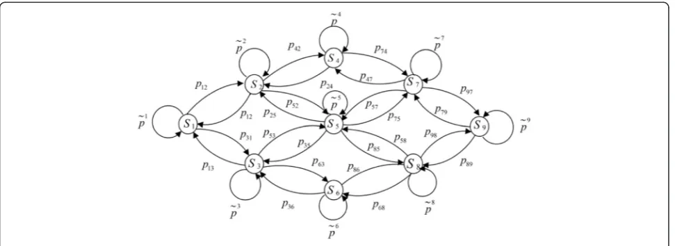
With the above formulating policy, for a buffer-aided MLS system with K= 2 and L= 2, we have the state and the corresponding state transition diagram as shown in Fig. 2. In the state transition diagram, for a given sate su, p~u denotes the probability that the
state su remains unchanged, and pnu denotes the
probability of the transition from state su to sn, i.e., pnu= Pr(su→sn). Since we assume that all relay
chan-nels experience the non-identically distributed fading, in general, we have pn1u≠pn2u for the state transition that can happen. On the other hand, for the one that cannot occur, there is no connectivity in the state dia-gram, and pnu= Pr(su→sn) = 0. With the state
transi-tion diagram, the state transitransi-tion matrix A can be achieved as well as the stationary state probability vector.
3 Exact outage performance
In this section, we investigate the exact outage per-formance of the buffer-aided MLS schemes. In MLS schemes, at state su, if the selected S-R or R-D
trans-mission is failed, there is one outage event. The prob-ability that an outage event occurs depends on the available S-R or R-D links. Therefore, to obtain the outage probability, we define two sets Nu
SR and NuRD for state su, where NuSR contains the indices of all re-lays when the corresponding S−R links are available for S−R transmission at state su (the corresponding
buffers are not full), and Nu
RD contains the indices of all relays when the corresponding R−D links are achievable for R−D transmission (the corresponding
buffers are not empty). The cardinalities of NuSR and
NuRD are given by NuSR and NuRD , respectively. Thus, for a given state su, if there is one outage event, then
no change in buffer state occurs. In state diagram, at the current state su, the corresponding outage
prob-ability is given by ~pu. In state transition matrix, the entries Auu in the main diagonal stand for the outage
probability at state su. Obviously, we have ~pu¼Auu. By considering all possible states, the average outage probability of the systems is formulated as
Pout¼
X
Mþ1
ð ÞK
u¼1
πuAuu¼
X
Mþ1
ð ÞK
u¼1
πup~u ð4Þ
In Eq.(4), the stationary distribution π is given by Eq. (3). From Eq. (4), it is found that, to obtain the outage probability, the probability p~u and the state transition matrixAare required.
3.1p~u: outage probability at state su
As stated previously, depending on which relay re-ceives or transmits data, the buffers move from the current state su to several possible states. Therefore,
we can divide all possible states to which can be moved from the current state su into two sets, UuSR−n and UuRD−n, where UuSR−n contains all states to which su
can move when one S−R link is selected and Uu−n RD contains all states to which su can move when oneR−D
link is selected.
At the same time, from Eq. (2), it is observed that for the statesuthere are NuSR and NuRD terms in the first
and second part maximizations within the “outer” max operation, respectively. Therefore, with Eq. (2), for state
su, we define the equivalent SNRs
γu the max-link selection for the overall system. The outage probability corresponding to the pair Nu
SR; NuRD
whereγthis the predefined outage threshold which is de-termined by the spectral efficiency, transmission power P, and additive noise power N0. With the consideration that all relay channels obey the i.ni.d Nakagami-m fading, using Eq. (1) leads to the first term in Eq. (6)
With similar reason, the second term in Eq. (6) is written as
Finally, the outage probability ~pu at the state su
can be achieved by substituting Eqs. (7) and (8) into Eq. (6).
3.2 Anu: the (n,u)th entry of transition matrix A
Besidesp~u, to obtain the total outage probability, Eq. (4) indicates that the stationary distribution π is also re-quired. At the same time, the Eq. (3) shows that the stationary distribution π depends on the transition matrix A. Because all relay links exhibit non-identical fading, at any time, the probabilities to select the S−R
and R−D transmissions are not the same. This is very different from the existing buffer-aided MLS schemes where all relaying links exhibit identical dis-tribution and the selection of any available link is equally likely. With this observation, we define puSR
and puRD as the probabilities that the S−R and R−D
transmissions are selected at state su, respectively. It
is clear that we have pu
SRþpuRD¼1 . We also define pnNu
SR as the probability that the best S−R link is
se-lected from the available Nu
SR S−R links such that the state transition su−>sn occurs and pnNu
RD is the
probability that the best R−D link is selected from the available Nu
RD R−D links such that the state transition su−>sn occurs. Therefore, the probabilities
to select one S−R link and one R−D link at state su
are formulated, respectively, as
pðSRu;nÞ¼pnNu
With these observations, the Anu entry of the state
transition matrixAis expressed as
Anu¼
3.3puSR: probability that theS-Rtransmission is selected at state su
At statesu, if there is noS−Rlink available (i.e., NuSR ¼0), we have the probability pu
SR¼0. On the other hand, if there is noR−Dlink available (i.e., Nu
RD ¼0), puSR¼1. For other case (i.e., NuSR ≠0 and NuRD ≠0), the probability pu
SRis formulated as
pu
RDð Þy is the probability density function of the
RV γu
. By using order statistics [33],
where∑1∑2are defined, respectively, by
The proof of Eq. (13) is presented in Appendix 1.
3.4pnNu
SR is the probability that the bestS−R
link is selected from all available NuSR S-Rlinks such that the state transitionsu−>snoccurs and pnNu
RD is the
prob-ability that the bestR−Dlink is selected from all available
Nu
RD R−Dlinks. Moreover, at the current state su, for
given state transitionsu−>sn, the selectedS−RorR−D
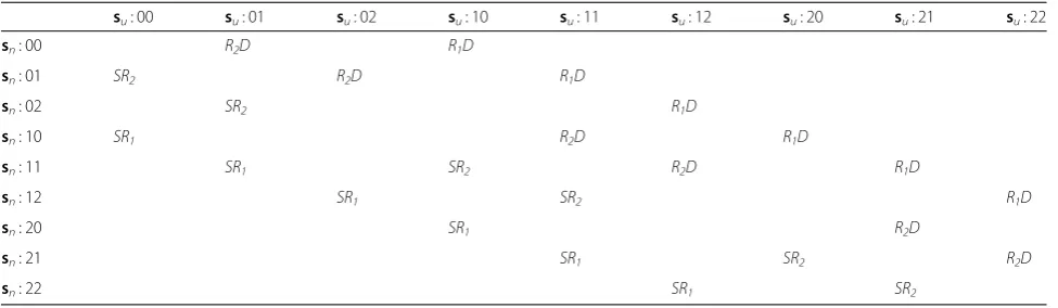
link is determined, which can be obtained from state tran-sition table. To illustrate this consideration, in Table 1, we present the selectedS−RorR−Dlink for each state tran-sition su−>sn, where we take K= 2 and L= 2. We have
the statesu= {Ψu(Q1),Ψu(Q2)}. Table 1 shows clearly that, for each given state transitionsu−>sn, the selectedS−R
orR−Dlink is determined. For example, when the state transition 11−> 10 occurs, the R2D link is selected for data transmission.
Therefore, with the above observation, without loss of generality, we assume that the ath element in Nu
SR or NuRD is selected so that the state transition su−>sn
arises. We first consider pn Nu
SR. Since there is only one
possible link is selected, the probabilitypn Nu
a is the function of u and n. Therefore, by using order statistics [33], after appropriate mathematic manipula-tion, the probabilitypn
Nu
The proof of Eq. (17) can be found in Appendix 2. Similar to Eq. (17), the closed-form expression of
pn Nu
RD can be achieved, which has the similar form as
Therefore, by substituting pnNu
RD, Eq. (17), and Eq. (13)
into Eq. (10), we can obtain A. Then, using Eq. (3) leads to the stationary state probability vector π. Finally, sub-stitutingπand p~u given by Eq. (6) into Eq. (4), the out-age probability is achieved.
4 Asymptotic performance analysis
In previous sections, we obtain the outage probability of the buffer-aided MLS schemes over the i.ni.d Nakagami-m fading channels. To highlight insight, in this section, we consider some special cases, i.e., asymmetric relay channels and symmetric relay chan-nels. We mainly discuss the probabilities pu
SR, pnNu SR,
and pnNu RD.
4.1 Identically distributed and asymmetric relay channels
When the identically distributed and asymmetric relay channels are considered, we havemSRk ¼mSR,ωSRk ¼ωSR,
and mRkD ¼mRD, ωRkD ¼ωRD, butmSR≠mRD,ωSR≠ωRD.
For such case, we first consider the case where |ωSR−ωRD|
is little, relatively. Due to the fact that the numbers of available links for S−R and R−D transmissions at state su are NuSR and NuRD , respectively, using the
results in [35] and [36] leads to the probability pu SR in Eq. (12) is written as
where N
n ¼
N!
n!ðN−nÞ! is binomial coefficient. For a more tractable form, using the multinomial expansion theorem, in Eq. (19), the first multinomial is written as
X
multinomial coefficient. Similarly, in Eq. (19), the second multinomial is written as
X
Therefore, for the identically distributed and asym-metry case, the probability of the S-R transmission selected is
With Eq. (23), havingpmRD¼1−pmSR. For pn
Nu
SR, according to Eq. (17), when the all S−R
channels are i.i.d fading, the probability pn Nu
Similarly, when all R−Dchannels are i.i.d fading, the probabilitypn
By substituting Eqs. (23), (24), and (25) into Eq. (10), we can obtain the state transition matrix A as well as the resulting stationary state probability vector π from Eq. (3) for the identically distributed and asymmetric relay channels.
4.2 Symmetric caseðωSRk ¼ωRkD¼ω; mSRk ¼mRkD¼mÞ
For the symmetric case (or i.i.d case), we have mSRk
¼mRkD¼m and ωSRk ¼ωRkD ¼ω , k∈{1,…,K}.
Therefore, the probabilitypmSRthat theS−Rtransmission is selected is given by
PuSR ¼1−NuRD
The probability pm
RD to select R−D transmission at statesmis
5 Diversity and coding gains
In this section, we consider the diversity and coding
gains. To this end, in Eq. (6), we denoteγth¼γth
0
P, where
γth' is determined by the spectrum efficiency. It is well
known, when x→0, the incomplete gamma function ϒ
However, Eqs. (29) and (30) show that it is challenging to achieve the diversity order due to the i.ni.d assump-tion. Therefore, we resort to the asymptotic analysis for the diversity and coding gains. We consider the iden-tically distributed and asymmetric fading channels, ωSRk ¼ωSR, ωRkD¼ωRD, ωSR≠ωRD, mSRk ¼mRkD¼m.
With this assumption, Eq. (29) is given by
~
With the consideration that the distribution of
Nm SR;NmRD
depends on both the number of relays K
and the relay buffer size L, we consider the following two special cases. Firstly, when the buffer sizeL= 1, we always have Nm
SR þ NmRD ¼K. The outage probability this case,πuis independent fromγ
'
. Therefore, substitut-ing Eq. (32) into (30), we have that the diversity order is
Gd¼ lim
which is the lower bound. On the other hand, when the relay buffer size L−>∞, it can be shown that the probabilities for NmSR ¼K and NmRD ¼Kare one. Cor-respondingly, the max link is selected from 2Kavailable links, and NmSR þ NmRD ¼2K. The diversity order is
Gd¼2mK ð35Þ
The result shows that the diversity order is close to 2mK, which is upper bound. In general, the diversity order of the considered scheme is betweenmKand 2mK
and increasing with the buffer size L due to the asym-metry. With the diversity order, the coding gain is writ-ten as
6 Average packet delay
The use of buffers at the relays improves the perform-ance at the expense of a higher packet delay in systems. The delay is a main issue of the buffer-aided relaying systems. Especially, the packet delay problem is becom-ing more severe in MLS schemes. This is because that in MLS schemes, the best link is selected from all available
S-Rand R-Dlinks. In this case, the weak links may have severe effect on the buffer-aided MLS relay systems. For example, we consider a MLS system with two relays, where the channel average powers of S−R and R−D
because that in each time slot, a relay node must be se-lected for receiving or forwarding data packet. There-fore, without losing the generality, in sequent, we assume that the average throughput is 1 (packet/slot). Therefore, when a packet is“waiting”for transmission at a node, another packet must be transmitted to another node. According to Little’s law, the average packet delay at a given relay node can be formulated as
E Df g ¼k
EfΨð ÞQk g
ηk
; k∈f1;…;Kg ð37Þ
where E{Ψ(Qk)} and ηk are the average queuing packet length and throughput at relay node Rk. Therefore, the average arrival rate into the buffer of the relayRkis given by
ηk¼
X
Lþ1
ð ÞK
u¼1
πupuSRηkNu
SR ð38Þ
In Eq. (38),puSR is defined by Eq. (13);ηkNu
SR denotes the
probability that the kth relay is selected for receiving data at state su, which has the similar form as pnNu
SR. At
the same time, the average queuing packet length at the relayRkis
EfΨð ÞQk g ¼ X
Lþ1
ð ÞK
u¼1
πuΨuð ÞQk ð39Þ
Hence, substituting Eqs. (38) and (39) into Eq. (37), we can obtain the average packet delay at relayRk.
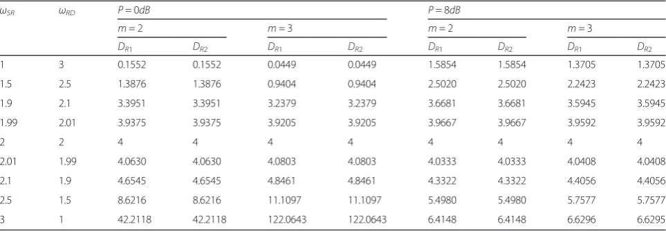
The above discussion indicates that the i.ni.d fading causes not only the degradation in diversity and coding gains but also the different average packet delays at re-lays. To achieve a perspective, in Tables 2 and 3, by tak-ingωSRk ¼ωSR, ωRkD¼ωRD, andωSR= 4−ωRD,k= 1,…,
K, we present the average packet delay comparison
analysis. From Table 2, it is easy to see that when the conditions ωSRk ¼ωSR and ωRkD¼ωRD are satisfied, the
average data packet delays at all relay are same. This is due to the fact that under the identical distribution, each relay is selected with equal probability for receipt or transmission data. It is also seen that for the different values of ωSR/ωRD, the average packet delays at each
relay are different greatly. We see that the average data packet delay is increasing with the value of ωSR/ωRD.
When (ωSR/ωRD) = 1, i.e., ωSR=ωRD, the average packet
delays at all relays equal to KL. When (ωSR/ωRD) > 1,
the average packet delays are greater than KL. How-ever, when (ωSR/ωRD) < 1, the average packet delays
are smaller than KL. This is not surprising because the higher relay-destination link gains imply that the relay-destination is more likely to be selected and the data packet are more quickly forwarded to the destination.
By taking K= 3, L= 3, and m= 2, in Table 3, we present the average packet delays at all relays under dif-ferent channel realizations. These difdif-ferentS-Rlink pow-ers are arbitrarily generated by Gaussian random vector with mean μ= 1.5 and variance σ2= 0.1, 0.2, 0.33, 0.5, 0.6, 0.8 and 0.9, respectively. Different from the results in Table 2, from Table 3, we see that the average packet delays at different relays are different entirely when the relay channels follow the non-identical distribution. Be-sides this, Table 3 also displays that, due to the different link powers for each system realization, the packet de-lays at different rede-lays are also different greatly. For com-parison analysis, in Table 3, we also present the total
average delay defined by DR¼K1
XK
k¼1
DRk. Table 3 shows
clearly that when σ2≤0.8, the total average delay DR is increasing with the disparity among the all S-R link powers.
Table 2Average data packet delay (slots) (K= 2,L= 2)
ωSR ωRD P= 0dB P= 8dB
m= 2 m= 3 m= 2 m= 3
DR1 DR2 DR1 DR2 DR1 DR2 DR1 DR2
1 3 0.1552 0.1552 0.0449 0.0449 1.5854 1.5854 1.3705 1.3705
1.5 2.5 1.3876 1.3876 0.9404 0.9404 2.5020 2.5020 2.2423 2.2423
1.9 2.1 3.3951 3.3951 3.2379 3.2379 3.6681 3.6681 3.5945 3.5945
1.99 2.01 3.9375 3.9375 3.9205 3.9205 3.9667 3.9667 3.9592 3.9592
2 2 4 4 4 4 4 4 4 4
2.01 1.99 4.0630 4.0630 4.0803 4.0803 4.0333 4.0333 4.0408 4.0408
2.1 1.9 4.6545 4.6545 4.8461 4.8461 4.3322 4.3322 4.4056 4.4056
2.5 1.5 8.6216 8.6216 11.1097 11.1097 5.4980 5.4980 5.7577 5.7577
7 Weighted-based MLS schemes
The non-identical fading imposes the great impact on diversity and coding gains as well as the average packet delay. As a result, the MLS schemes may be unstable. Here, we consider a modified buffer-aided MLS scheme that can overcome the performance loss and degrade the packet delays at all relays over the i.ni.d fading channels. One of the ways of doing it is introducing two additional weight vectors ωw
SR and ωwRD, such that the selection of the best link in MLS schemes is based on the equivalent
S-Rlink power vectorωESR ¼ωwSR:ωSR and the equivalent R-Dlink power vectorωE
RD¼ωwRD:ωRD. In general, there are three methods to determine the weight vectors ωw
SR and ωw
RD, which are referred as max-weight, min-weight, and mean-weight methods, respectively. Nevertheless, the weight vectorsωw
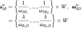
SR and ωwRD can be given by the fol-lowing form.
ωw SR¼
1 ωSR1
;…;ω1
SRK
W; ωwRD
¼ λ
ωR1D
;…;ωλ
RKD
W ð40Þ
whereλis a power adjusting factor so that the equiva-lent transmission power ofR-D links is greater than the one ofS-Rlinks a litter. In practical implementation, the power adjusting factorλcan be determined by the toler-able maximum delay and maximum outage probability. As a result, the delay performance of MLS schemes is improved greatly. For max-weight and min-weight schemes, in Eq. (40), we have W= max{ωSR,ωRD} and
W= min{ωSR,ωRD}, respectively. The max-weight and min-weight schemes are suitable for the scenario where the disparity of all relay channel powers (or variances) is small relatively. However, in practical implementation, due to the different relay positions and heavy fading, the disparity can be very large. To overcome this problem, we propose the mean-weight scheme, in which the weight factor W is given by the following algorithm in Table 4.
The proposed algorithm can be implemented in a centralized or distributed manner. Here, we employ a hybrid distributed-centralized manner to select the best link. This is due to the fact that determining weight fact W requires the statistical channel state in-formation (CSI) of all links. At the same time, in practical communication systems, the distributed manner is preferable for the selection of the best link, especially in the case where the number of contention links is very large. For such hybrid manner, before each time slot, each relay transmits the statistical CSI to the central controller, which can be obtained by listening pilot signals from source and destination. After receiving the statistical CSI from all relays, the central controller performs the algorithm given in Table 4 and broadcasts the result to all relays. Upon receiving the signal from central controller, each relay then starts a timer by jointly considering the buffer sates and its input (S-R) and output (R-D) link strength as well as the weight factor W obtained from central controller. The duration of timer is a propor-tional function that depends on the weight factor W
and S-R or R-D link strength. As a result, the best link can be selected.
Note that, due to the introduction of weight factor W, the selection of the best link in W-MLS schemes is based on the equivalent S-R link power vector ωE
SR¼ωwSR:ωSR and the equivalentR-Dlink power vectorωE
RD¼ωwRD:ωRD. Therefore, the W-MLS obtains the following advantages over the conventional MLS schemes [26]. Firstly, all S-R
and R-D links are selected with equal probability so that the maximum diversity and coding gains can be achieved. Secondly, at all relays, the average packet delays are same. Therefore, our W-MLS schemes overcome the unbalance caused by the no-identical fading. Finally, in our W-MLS schemes, the average packet delays can be further de-creased by adjustingλas shown in Table 4.
Of cause, the superiority of W-MLS over the conven-tional MLS is achieved at the price of system complexity. This is because that the weigh factor W must be
Table 3Average data delay (slots) (K= 3,L= 3, m= 2) σ2
ωSR P= 0dB P= 8dB
DR1 DR2 DR3 DR DR1 DR2 DR3 DR
0.1 1.3612, 0.9315, 1.7658 1.8535 1.3082 2.8242 1.9953 3.0862 2.4753 3.9014 3.1543
0.2 1.6428, 1.6399, 1.1132 2.9223 2.9136 1.7735 2.5365 4.0000 3.9929 2.8869 3.6266
0.33 1.7804, 1.3981, 1.3874 3.6287 2.4657 2.4405 2.8456 4.5572 3.5689 3.5440 3.8900
0.5 2.5036, 1.7062, 1.6399 9.2559 6.7472 6.3987 7.4673 9.8060 7.5676 7.3297 7.9944
0.6 1.7259, 1.6532, 2.7298 7.5342 7.1323 9.5558 8.0741 8.5251 8.2828 9.4977 8.7685
0.8 2.9201, 0.7805, 2.1231 10.1753 5.5529 10.8074 8.8452 8.8741 8.7285 9.3704 8.9910
determined firstly before performing the best link selec-tion. From Table 4, we see that when the mean-weight MLS scheme is employed, the complexity depends on the disparity of channel gains. That is to say, the com-plexity is increasing with the disparity. On the contrary, as a candidate of complexity-performance trade-off, the max-weight or min-weight scheme has low employment complexity. Obviously, when the disparity of channel gains is high, the mean-weight MLS should be per-formed so that the system performance is improved greatly. When the disparity of channel gains is small, the
max-weight or min-weight scheme is a good selection with low implementation complexity and improved performance.
8 Numerical results and simulations
Based on the previous analysis and derivations, the sim-ulated and numerical results are presented in this sec-tion. To obtain a comprehensive comparison, the T-BRS and MMLS schemes are also analyzed in this section. For simplicity, throughout the simulations, we take the system spectrum efficiency R= 1 bits/s/Hz. We also
assume that the fading severity factors are same, i.e.,
mSRk ¼mRkD¼m, for all Nakagami-mfading links.
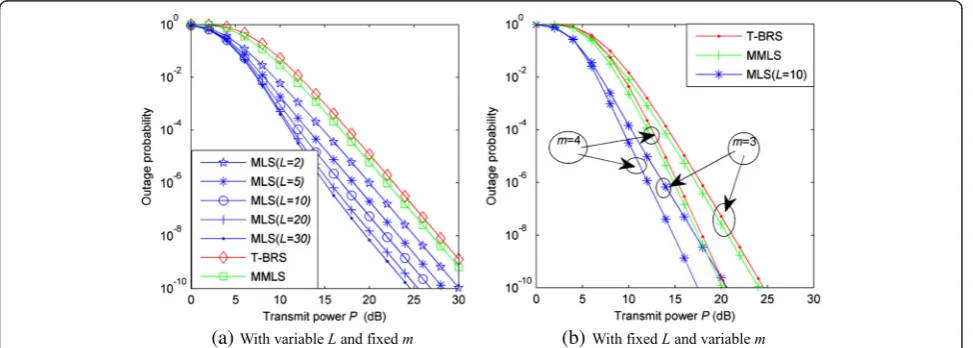
By taking the number of relaysK= 2 and the fading se-verity factorm= 2, in Fig. 3, we first investigate the out-age probability versus the transmit power P with different sizeLof relay buffers over the i.i.d Nakagami-m
fading channels. Specially, we take the buffer’s size
L= 2, 5, 10, 20, and 30, and fωSRkg
K
k¼1¼fωRkDg
K k¼1¼1 .
From Fig. 3a, it is clearly shown that the MLS schemes al-ways outperform the T-BRS and MMLS schemes when the relay channels follow the i.i.d Nakagami-mfading. The MLS schemes provide not only the coding gain but also the diversity gain over the T-BRS and MMLS schemes. Moreover, the achievable diversity gain by MLS over T-BRS and MMLS is increasing with the increase of the buffer’s sizeL. To further illustrate the impact of the fad-ing severity factormon the diversity order, in Fig. 3b, the outage probability is investigated by taking the fixed buffer sizeL= 10 and taking the variable fading severity factorm,
m= 3,4. It is found that the performance of the three buffer-aided relaying schemes is enhanced by the increase of m. Similar to Fig. 3a, we see that for each fixed m in Fig. 3b, the MLS schemes always outperform the T-BRS and MMLS ones. This is due to the superiority provided by the MLS schemes.
In Fig. 4, the outage probability of the three buffer-aided relaying schemes is investigated over more general i.ni.d Nakagami-m fading channels, in which there are two different channel realizations are considered, re-spectively. Different from the results achieved in Fig. 3, from Fig. 4, we achieve that when the relaying channels experience the non-identical fading, all curves in Fig. 4a have the same slope, approximately. This observation in-dicates that in this non-identically distributed fading case, the MLS scheme does not provide the diversity
gain over the T-BRS and MMLS schemes, or only givens very limited diversity gain. At the same time, it is also achieved that although the MLS schemes outperform the T-BRS, it has the same performance as MMLS schemes in certain case. For example, Fig. 4b shows that the achieved coding gains by MLS over MMLS are nom-inal. Obviously, the performance loss is increasing with the disparity of the channel variances. Therefore, we have the following results. (1) When all relaying channel experience i.i.d fading, compared with the both T-BRS and MMLS schemes, the MLS schemes provide not only the coding gain but also the diversity gain. Moreover, the achievable diversity order is increasing with the buffer’s sizeL. (2) When all relaying channels experience i.ni.d fading, the performance of the MLS schemes is im-paired greatly by the disparity of relaying channels. On the one hand, the MLS schemes only provide the very limited diversity gain over the T-BRS and MMLS schemes. In an extreme case, there is no diversity gain achieved even if the buffer sizeLis large enough. On the other hand, the achieved coding gain is also limited. Spe-cially, in certain case, the MLS schemes can be inferior to the MMLS schemes even if the MLS schemes always achieve the coding gain over the T-BRS.
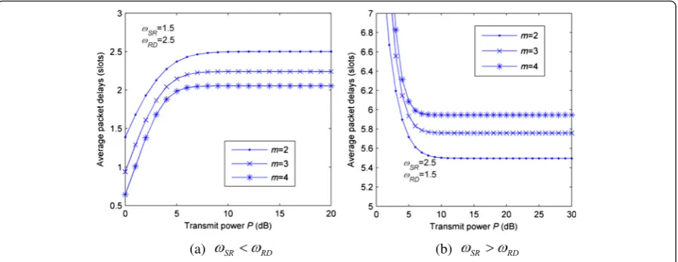
In Fig. 5, we plot the average packet delay versus the transmit power P under different m for the case ωSRk ¼ωSR, ωRkD¼ωRD, ωSR≠ωRD, k= 1,…,K.
Com-paring Fig. 5a, b, we find that, for the two considered cases, ωSR<ωRD and ωSR>ωRD, the system parameters P and m impose different impact on the average packet delay. When ωSR<ωRD, the average packet
delay is proportional inversely with the fading severity factor m. This observation indicates that when the condition ωSR<ωRD is satisfied, the systems with
lar-ger m obtain not only higher diversity gain but also
(a) (b)
less average packet delay. However, when ωSR>ωRD,
compared with Fig. 5a, Fig. 5b shows that the average packet delay is increasing with m. For the effect of the transmit power P, Fig. 5a, b shows that when the transmit power P is large enough, the average packet delay is not affected by P and saturated to a constant. The reason is that when the transmit power P is large enough, the difference of equivalent SNRs between the S-R and R-D links is negligible, such that all links are selected with equal probability and the delay ap-proaches a constant. On the contrary, when the trans-mit power P is small relatively, Fig. 5a shows that the increase of P causes the increase of the average packet delay, while Fig. 5b shows that it causes the decrease of the average packet delay.
Similar to Fig. 5, to observe the average packet de-lays at different rede-lays over non-identical fading chan-nels, by taking fωSRKg
K
k¼1¼f1:3612; 0:9315; 1:7658g
and fωSRKg
K
k¼1¼f2:6388; 3:0685; 2:2342g, the
corre-sponding average packet delays versus the transmit power are plotted in Fig. 6a, b, respectively. The figure shows clearly that when the relay channels obey non-identical distribution, the delays at different relays are different. Moreover, the asymptotic delays are also dif-ferent when the transmit power goes large enough.
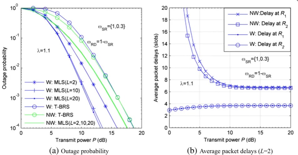
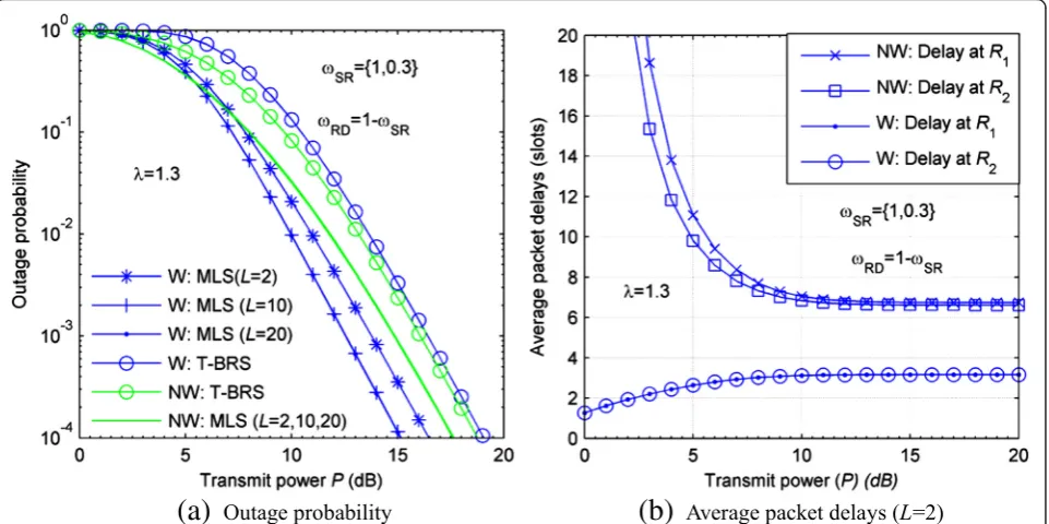
To illustrate the feasibility and superiority of the pro-posed weight-based MLS schemes, in Figs. 7 and 8, we compare the outage performance and average packet de-lays among the weight-based and non-weight-based schemes, where we take K= 2, m= 2, ωSR= {1, 0.3},
(a) (b)
Fig. 5Average packet delays versus transmit power (L = 2, K = 2)
ωRD= 1−ωSR. In Figs. 7 and 8, “W” stands for the proposed weight-based schemes, while “NW” stands for the non-weight-based schemes. For a fair compari-son, the following power constraint is adopted.
PW
2K
XK
k¼1 W ωSRk
þXK k¼1
Wλ ωRkD
" #
¼P ð41Þ
where PW denotes that transmission power at each node when the proposed weight-based schemes is used
to select the best link (or relay). In the two figures, we only consider the T-BRS and MLS schemes with or with-out the proposed weight-based method. From Fig. 7a, we see that the effect of weight-based schemes on the outage performance of both the T-BRS and MLS schemes is different greatly. Specially, for the T-BRS schemes, it is easily seen that the proposed weight-based schemes do not improve outage performance, instead of increasing the outage probability, especially in the low region of transmission power P. Only in medium and
(a)
(b)
Fig. 7Comparison of outage and delay performance between the weight-based and non-weight-based schemes (m= 2,K= 2,λ= 1.1,NW
non-weight-based schemes,Wweight-based schemes)
high region of P, the loss will be reduced gradually. In high P, the weight-based schemes obtain the same out-age performance as the non-weighted-based ones. How-ever, for the MLS schemes, it is clearly found that the proposed weight-based methods cause greatly improve-ment on outage performance over the entire region of transmission power P. For example, Fig. 7a shows that when the power adjusting factor λ= 1.1 and L= 20, the weight-based MLS schemes achieve the power gain of 5 dB over the traditional MLS schemes at 10−4of outage probability. At the same time, another interesting result can also be found in Fig. 7b. Figure 7b shows that, with the proposed weight-based MLS, the packet delays at all relays are improved greatly. On the one hand, the delays at all relays are the same entirely, which indicates that all data packets can be forwarded to destination with equal probability. On the other hand, the average packet delay at each relay is reduced distinctly, especially in low region of transmit powerP. Therefore, it is obtained that the proposed weight-based schemes not only can im-prove the outage performance but also can decrease the average packet delay. The proposed W-MLS schemes are feasible.
For more insight, in Fig. 8, the outage and delay per-formance are compared once again. In the figure, we take the power adjusting factor λ= 1.3. Comparing Figs. 7a and 8a, we see that the increase of the power adjusting factor λ yields the loss in the outage perform-ance of the weight-based MLS schemes. For example,
when L= 20, Fig. 8a shows that the weight-based MLS schemes only achieve the power gain of 3 dB over the traditional MLS schemes at 10−4 of outage probability. On the contrary, Fig. 8b shows that the average packet delays for the proposed weight-based MLS schemes are decreasing with the power adjusting factorλ. This is due to the fact that the outage probability of relay systems is increasing with the symmetricity of relay channels. When the channels are symmetric entirely, the relay sys-tems achieve the optimal outage performance. There-fore, we have the result that the increasing power factor yields the increasing outage probability. However, when the equivalent power ofR-Dlinks is greater than the one ofS-Rlinks, the probability that oneR-Dlink is selected is greater than the one that one S-Rlink is did. The re-sults from Figs. 7 and 8 indicate that in practical applica-tion, the power adjusting factor λ should be jointly determined by the maximum delay, maximum outage probability, etc. As a result, the proposed W-MLS scheme is a delay-diversity trade-off scheme.
9 Conclusions
While it has been proved that in buffer-aided relaying systems, the MLS schemes can provide both the diver-sity and coding gains over the T-BRS and MMLS schemes when the all relay channels obey the i.i.d fading, the corresponding diversity and delay performance of the MLS schemes have not been reported when the relay channels experience the practical i.ni.d fading. Thus, in
(a)
(b)
Fig. 8Comparison of outage and delay performance between the weight-based and non-weight-based schemes (m= 2,K= 2, λ= 1.3,
this paper, the MLS schemes are investigated over the i.ni.d Nakgami-mchannels. By employing Markov chain model, the statistical descriptions of the MLS schemes are achieved firstly. Then, with the derived statistical de-scriptions, the average packet delays are investigated over the i.ni.d Nakgami-mfading channels. The obtained results show that the non-identically distributed relay links impose a severe loss in the diversity and coding gains for the MLS schemes. Moreover, when the dispar-ity of the powers of relay links is very large, the MLS schemes no longer provide any diversity gain over the T-BRS and MMLS ones even if the buffers’size is enough large. However, when the disparity of the powers of relay links is little relatively, the enough diversity and coding gains can be still provided by the MLS schemes. For the average packet delays, it is achieved that under the i.ni.d fading channels, the average packet delays at all relays are different. The results indicate that at some relays, the average packet delays can be very large, and at other relays, they are small. This phenomenon yields that at some relays, the data packets would be trapped for a long time and the relay systems with MLS schemes are unstable. However, it is enough lucky that when the powers ofS-Rlinks are less than the ones ofR-Dlinks, the average packet delays are reduced evidently. Inspired this observation, a W-MLS diversity-delay trade-off scheme is proposed to reduce the delay and to enhance the stability of MLS schemes but still obtain the enough diversity and coding gains over T-BRS and MMLS schemes. In the pro-posed W-MLS schemes, before selecting a best link, the systems multiply the link gains by a weight vector, such that the equivalent signal-to-noise ratios of S-Rlinks are same, so does the ones of R-D links, such that the data packet delays at all relays are same. By adjusting the weight vector, it is guaranteed that the equivalent SNRs of
R-Dlinks are greater than the ones ofS-Rlinks, such that the delays can be decreased evidently. Moreover, by de-signing feasible weight vector, the W-MLS can still pro-vide the enough diversity and coding gains.
10 Appendix 1: Proof of Eq. (13)
With the definition γu
SR¼|ffl{zffl}max ing the Nakagami-m distribution with parameters mSRk
andωSRk, in Eq. (12) the term Pr γ can been written as
Pr γu
At the same time, to obtain the closed-form expres-sion offγu required. To this end, we first consider its CDF Fγu
RDð Þ.y
With γRkD following Nakagami-m distribution with pa-rametersmRkDandωRkD, having
Taking the derivative of Fγu
RDð Þy with respect to y, we
Thus, by substituting Eqs. (46), (45, and (43) into Eq. (12) and using (3.351.3) in [34], we have the probability pmSR given by Eq. (13).
11 Appendix 2: Proof of Eq. (17)
According to Eq. (16), at state suthe probability pnNu SR is
definition YNu
SRð Þa ¼max
Using the results in [35] and [36] we have
FYNuSRð Það Þ ¼y
Substituting Eqs. (50) and (49) into (47), after some al-gebraic manipulations, we have the closed-form expres-sion ofpn
Nm
SR that is given by Eq. (17).
Competing interests
The authors declare that they have no competing interests.
Acknowledgements
The authors thank the editors and the anonymous reviewers for their constructive comments and suggestions, which helped to improve the quality of this paper. This work was supported by the Natural Science Foundation of China under Grant 61261015, the 973 project 2013CB329104, the Natural Science Foundation of China under Grant 61561043, 61372124, and 61302100, the Natural Science Foundation of Gansu Province for Distinguished Young Scholars (1308RJDA007), and the Foundation Research Funds for the University of Gansu Province:“Massive MIMO channels modelling and estimation over millimeter wave band for 5G”.
Author details
1College of Computer Science and Engineering, Northwest Normal
University, Lanzhou 730070, China.2Wireless Communication Key Lab of
Jiangsu Province, Nanjing University of Posts and Telecommunications, Nanjing 210003, China.3Key Lab of Broadband Wireless Communication and Sensor Network Technique of Ministry of Education, Nanjing University of Posts and Telecommunications, Nanjing 210003, China.
Received: 11 September 2015 Accepted: 21 December 2015
References
1. J Xiangdong, Y Longxiang, F Haiyang, Tight performance bounds for two-way opportunistic amplify-and-forward wireless relaying networks with TDBC protocols. EURASIP J. Wirel. Commun. Netw.2011, 1–8 (2011) 2. J Xiangdong, Y Longxiang, Upper and lower bounds of two-way
opportunistic amplify-and-forward relaying channels. IEEE Commun Lett 16(8), 1180–1183 (2012)
3. ECVD Meulen, Three-terminal communication channels. Adv. Appl. Probab. 3(1), 120–154 (1971)
4. T Cover, AE Gamal, Capacity theorems for the relay channel. IEEE Trans. Inf. TheoryIT-25(5), 572–584 (1979)
5. A Host-Madsen, Z Junshan, Capacity bounds and power allocation for wireless relay channels. IEEE Trans. Inf. Theory51(6), 2020–2040 (2005) 6. A Sendonaris, E Erkip, B Aazhang, User cooperation diversity—Part I. System
description. IEEE Trans. Commun.51(11), 1927–1938 (2003) 7. A Sendonaris, E Erkip, B Aazhang, User cooperation diversity—Part II.
Implementation aspects and performance analysis. IEEE Trans. Commun. 51(11), 1939–1948 (2003)
8. J Laneman, D Tse, G Wornell, Cooperative diversity in wireless networks: efficient protocols and outage behavior. IEEE Trans. Inf. Theory50(12), 3062–3080 (2004)
9. A Bletsas, A Khisti, DP Reed, A Lippman, A simple cooperative diversity method based on network path selection. IEEE J. Sel. Areas Commun. 24(3), 659–672 (2006)
10. JN Laneman, GW Wornell, Distributed space-time-coded protocols for exploiting cooperative diversity in wireless networks. IEEE Trans. Inf. Theory 49(10), 2415–2425 (2003)
11. C Xu, S Ting-wai, QF Zhou, FCM Lau, High-SNR analysis of opportunistic relaying based on the maximum harmonic mean selection criterion. IEEE Signal Process Lett.17(8), 719–722 (2010)
12. I Krikidis, J Thompson, S McLaughlin, N Goertz, Max-min relay selection for legacy amplify-and-forward systems with interference. IEEE Trans. Wirel. Commun.8(6), 3016–3027 (2009)
13. L Yingbin, VV Veeravalli, HV Poor, Resource allocation for wireless fading relay channels: max-min solution. IEEE Trans. Inf. Theory53(10), 3432–3453 (2007) 14. X Bing, F Yijia, J Thompson, HV Poor, Buffering in a three-node relay
network. IEEE Trans. Wirel. Commun.7(11), 4492–4496 (2008)
15. N Zlatanov, R Schober, P Popovski, Throughput and diversity gain of buffer-aided relaying, inPROC Of 2011 IEEE Global Communications Conference, 2011, pp. 1–6
16. N Zlatanov, R Schober, Buffer-aided half-duplex relaying can outperform ideal full-duplex relaying. IEEE Commun. Lett.17(3), 479–482 (2013) 17. A El Shafie, MG Khafagy, A Sultan, Optimization of a relay-assisted link
with buffer state information at the source. IEEE Commun. Lett. 18(12), 2149–2152 (2014)
19. N Zlatanov, A Ikhlef, T Islam, R Schober, Buffer-aided cooperative communications: opportunities and challenges. IEEE Commun. Mag. 52(4), 146–153 (2014)
20. T Islam, DS Michalopoulos, R Schober, V Bhargava, Delay constrained buffer-aided relaying with outdated CSI, inProc of Wireless Communications and Networking Conference (WCNC), 2014 IEEE, 2014, pp. 875–880
21. T Islam, A Ikhlef, R Schober, VK Bhargava, Diversity and delay analysis of buffer-aided BICM-OFDM relaying. IEEE Trans. Wirel. Commun. 12(11), 5506–5519 (2013)
22. D Chen, Z Jing, Y Lie-Liang, H Yongkai, N SoonXin, L Hanzo, Energy-efficient buffer-aided relaying relying on non-linear channel probability space division, inProc Of Wireless Communications and Networking Conference (WCNC), 2014 IEEE, 2014, pp. 1979–1984
23. L Guan-Xing, D Chen, L Dong, L Guangtao, Z Yonghui, Outage analysis of dual-hop transmission with buffer aided amplify-and-forward relay, inProc Of Vehicular Technology Conference (VTC Fall), 2014 IEEE 80th, 2014, pp. 1–5 24. M Darabi, B Maham, Z Yan, Buffer-aided link selection for incremental
relaying systems, inProc. of Computers and Communication (ISCC), 2014 IEEE Symposium on, 2014, pp. 1–6
25. D Chen, Y Lie-Liang, Z Jing, N Soon Xin, L Hanzo, Energy, delay, and outage analysis of a buffer-aided three-node network relying on opportunistic routing. IEEE Trans. Commun.63(3), 667–682 (2015)
26. A Ikhlef, DS Michalopoulos, R Schober, Buffers improve the performance of relay selection, inProc. of 2011 Global Telecommunications Conference (GLOBECOM 2011), 2011 IEEE, 2011, pp. 1–6
27. A Ikhlef, DS Michalopoulos, R Schober, Max-max relay selection for relays with buffers. IEEE Trans. Wirel. Commun.11(3), 1124–1135 (2012) 28. I Krikidis I, T Charalambous, JS Thompson, Buffer-aided relay selection for
cooperative diversity systems without delay constraints. IEEE Trans. Wirel. Commun.11(5), 1957–1967 (2012)
29. Z Tian, G Chen, Y Gong, Z Chen, J Chambers, Buffer-aided max-link relay selection in amplify-and-forward cooperative networks. IEEE Trans. Veh. Technol.64(2), 553–565 (2014)
30. N Nomikos, T Charalambous, I Krikidis, D Vouyioukas, M Johansson, Hybrid cooperation through full-duplex opportunistic relaying and max-link relay selection with transmit power adaptation, inProc. of Communications (ICC), 2014 IEEE International Conference on, 2014, pp. 5706–5711
31. C Gaojie, T Zhao, G Yu, J Chambers, Decode-and-forward buffer-aided relay selection in cognitive relay networks. IEEE Trans. Veh. Technol. 63(9), 4723–4728 (2014)
32. B Vo Nguyen Quoc, TQ Duong, DB da Costa, GC Alexandropoulos, A Nallanathan, Cognitive amplify-and-forward relaying with best relay selection in non-identical Rayleigh fading. IEEE Commun. Lett. 17(3), 475–478 (2013)
33. HA David, HN Nagaraja,Order statistics, 3rd edn. (John Wiley, New York, 2003) 34. IS Gradshteyn, IM Ryzhik,Table of integrals, series, and products, 7th edn.
(Acdemic, San Diego, 2007)
35. TQ Duong, VNQ Bao, HJ Zepernick, On the performance of selection decode-and-forward relay networks over Nakagami-m fading channels. IEEE Commun. Lett.13(3), 172–174 (2009)
36. GC Alexandropoulos, A Papadogiannis, K Berberidis, Performance analysis of cooperative networks with relay selection over Nakagami-mfading channels. IEEE Signal Process Lett.17(5), 441–444 (2010)
Submit your manuscript to a
journal and benefi t from:
7Convenient online submission 7Rigorous peer review
7Immediate publication on acceptance 7Open access: articles freely available online 7High visibility within the fi eld
7Retaining the copyright to your article