© 2018 IJSRCSEIT | Volume 3 | Issue 5 | ISSN : 2456-3307
Image Retrieval Using the Centroid Based Shape Descriptor
Priyanka R Kabber1, Prof. J C. Karur2, Dr. Jagadeesh Pujari3
1M. Tech student in Computer Science , SDM College of Eng & Tech, Dharwad ,India 2Professor of CSE , SDM College of Eng & Tech, Dharwad ,India
3HOD of ISE, SDM College of Eng & Tech, Dharwad ,India
ABSTRACT
Shape analysis is used in many application field including security applications, medical field ,agricultural field,cyber crime and many more. A shape descriptor is the simplified representation of the images. These shape descriptor contain the information of that image which will help to store the image information and make easy comparison between the images or easy for matching the different shapes .The proposed method is centroid based shape descriptor. The type of shape descriptor used here is boundary based shape descriptor. Distance from center of bounding box encompassing the edge image to farthest point on the edge is calculated. A circle is drawn using the distance mentioned above as radius (the farthest distance between centroid and edge pixel). A line using Bresenham algorithm drawn between two opposite pixels on circle forms the bases of computation. Distances between all the edge pixels falling on the above mention line are computing , these distance matrix is nothing but the features extraction for image. The descriptor is divided into segments so as to avoid global distribution. A rotational matching scheme ensures invariance to rotation. As the computation of feature set is compact, implementation of this method results in quick retrieval of images invariant to scaling, translation and rotation.
Keywords: Centroid, Distances using Euclidean distance formula and Binning of Image
I.
INTRODUCTION
Image Processing is one of the field which helps to operate on the image content and image itself to make the best use of it. There are several crucial applications which apply image processing methods to exploit the image content and use it in different fields. Different fields of application include recognition of patterns, encoding and transmission, video processing, remote sensing, medical field, imaging microscopic contents, robot/machine vision and others. Every image is represented in binary. An image consists of small sized squares arranged in horizontal rows and are called pixels. The characteristics that an image displays are very essential. They are noise containing unwanted,
meaningless information, second characteristics is contrast that depicts the difference of the shades of luminance or gray level on image. The third characteristic is sharpness that is concerned with sudden changes of blackening at the corner parts. There are two methods are available to find the shape descriptor, they are boundary based and region based shape descriptor. Boundary based shape descriptor help in finding boundary pixels value of image.The shape descriptors contains information about boundary and inside region of objects.Here boundary based shape descriptor is used.
II.
SYSTEM MODEL1. Query Image: Query image is chosen randomly from the dataset. Query set is chosen in such a way that, it consist of one image from all classes (dataset consists of 70 class and each class contains 20 images).
Remaining steps are explained in next part in deatail.
Figure 1. system model
III.
IMPLEMENTATION
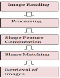
The implementation of proposed shape descriptor is implemented as follows (3.1).In this section explained detailed implementation of each step involved in finding the descriptor. The working of descriptor from feature extraction till similarity matching is divided into the following stages:
Figure 2. Flow diagram depicting working of the shape descriptor
3.1 Image Reading
Image reading is initial step in implementing this application. Images from MPEG7 dataset are read using the mat lab function imread ( ).
3.2 Processing
The image after being read goes the initial processing stages. The processing of images transforms the images in the form that are ready for further
processing such as signature extraction. The processing includes the following stages:
3.2.1. Binarization of image
It is a process of converting image into binary image. Binary image contains only two colours they are white(1) and black(0).The images in MPEG7 are mixture of binary and gray scale images(pixels value ranges between 0-255).Gray scale images are converted into binary images. Fig 3.2.1.1 shows the change in colour of pixels. Binary images show efficient calculation of distance from pixels to its nearest pixels. This feature helps in finding image centroid and in retrieval in image.
(a) ( b )
Figure 3. Images with different background.(a) image with white background;(b) Image with black background
3.2.2 Determining Edge Pixels
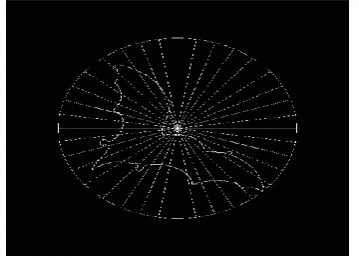
The edge pixels that form the shape of the image object is to be obtained. As the proposed method contour based shape descriptor, only the edge pixels are considered for computation.
Figure 4. Representation of edge pixel image
As we know that the image is already converted into binary format. So Now image has only two values 0 and 1. The logic behind zero crossing technique is considering the 3x3 matrix. Find the sum of matrix if the sum is 9 than all values of that matrix is 1 , it shows that pixel is not a edge pixel. If the sum is less than 9 than that pixel is an edge pixel. The bone image from the dataset obtained with only the edge pixels can be seen as in below Figure 4
3.2.3 Minimum Bounding Box
Minimum bounding box is used to constrain the image by removing the extra rows and extra column .For example the rows and column which has the zero value will not play important role in any shape analysis. So by removing such rows and column will not effect the image. It just make the image more perfect .After removing such rows and column , than need to find the minimum and maximum of row and column coordinates image. The row and column coordinates is nothing but the edge pixels having value 1 and 0. After finding the min and max of row and column coordinates than the image is constrained within bounding box.
3.2.4 Fitting circle around the centroid of the bounding box
Already min and max of row and column is calculated. So half of length of row and column is nothing but centroid of the image.
Once after calculating centroid of the image , need to calculate the radius. The distance between center and the farthest edge pixel is radius. The radius is calculated using the Euclidean distance formula. To find the distance between the centroid and to farthest edge pixel, need to calculate the distance from centroid to each edge pixel. And find the maximum among those distances ,that distance is nothing but radius. The Euclidean distance formula is calculated as:
Where (a1 , b1) and (a2 , b2) are coordinates of pixels
between which the distance is calculated.
Bresenham -Circle algorithm
Bresenham circle algorithm is used to get the coordinates of the circle. If we join those coordinates circle will form. To draw the circle, Bresenham-circle drawing algorithm is used. The algorithm takes the value of cropped image , centroid coordinates and radius value and returns the circle coordinates points. The first half of coordinates plotted is initial points and second half coordinates will be diagonally opposite points to the first half plotted points. Than the coordinate values returned are sorted and then plotted in the cropped image.
3.3 Shape Feature Computation
This part of implementation is very important and it plays a very important part in increasing accuracy or retrieval rate of image. This part includes two parts they are:
Binning
Calculation of distances
Centroid = [ (nR/2) ,(nC/2)]
Euclidean Distance = (a1-a2)
2
Binning
The circle encompassing the image is being segmented into 18 bins. Thus the first half circle is divided into 18 bins. This is to be applied only to the pixels which are covered on one half of circle and the circle binning. In following image we got 18 bins and calculated bin wise pixels like pixels which belongs to that bin will be recorded. At the end we will get 18 bins with respective to there pixel values. It covers entire image .All pixel value is recorder
A line using Bresenham algorithm drawn between two opposite pixels on circle forms the bases of computation. Bresenham-line will return all pixel value which all are lying on the line. In this set coordinates includes circle and image pixels value.
Need to extract only image pixel values. To get only image pixel value we need to apply intersection on PixArray coordinates which contains the image pixel value and image pixel coordinates ( which contain all image pixel value).This operation will generate the set of image coordinates lying on that line.
Now compute distance between each pixel to all pixels of PixelOnLine.This process continues for all size of first half circle pixels and opposite pixels values will also recorded automatically. This helps in reducing the computation.
Now find the maximum distance among all distance. Maximum distance is used to normalize the matrix which contain the all distances by dividing each distance by maximum distance. Now all the distances are in the range of 0.something to 1 but not zero .Find maximum and minimum distances. Any Histogram matching. Before matching the histogram first need to plot the histogram of all images present in that dataset . Shape matching includes two section one is histogram plotting and second section is histogram matching ,they are:
Histogram plotting
Histogram Matching
Histogram Plotting:
The local histogram is plotted of size number of bins cross 64.Means number of bins is an row and intermediate distances is an column (64). Bins number is on x axis and distances interval is on y axis.
Pts_Per_each_Bin =(NoOfhalfCirPts/ Noofbins);
[PixArray] = bresenhamLine (double (Coord2Mod(i,:)), double(Coord1Mod(i,:)));
PixelOnLine= intersect(EdgeMatrix, PixArray, 'rows'
);
PixelOnLine= intersect(EdgeMatrix,PixArray,'rows');
CrlBin = floor (i/PtsPerBin) + 1;
if (CrlBin > NoOfBins) CrlBin = NoOfBins ; end
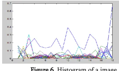
to be using min and max value which is to be calculated during computing distances. Than those distances is to be distributed on that bin and that interval. In this case size of histogram is of 18 x 64. So that for each bin one histogram is plotted.
Figure 6. Histogram of a image
Histogram Matching:
The histogram of query image is compared with the histogram of all dataset .But the way of matching is different. The histogram of one bin of image is compared with the histogram of other bin of query image. Thus the bin wise matching is done by relative way of rotating the bins.
Than the bins are rotated one by one and compared with the query image until the best match for the query image occurs. For doing so we need to set two flags. Flag 1 means clockwise rotation of bins and Flag 2 means anticlockwise rotation of bins of query image . Find the minimum distance of similarity between the histogram. Minimum distance means closer the result ( more is the image close) and maximum distance means query image is distinct or not so similar to the query image.
Figure 7. Bin wise rotational histogram matching
In histogram matching ,in the first iteration the nth bin of dataset image is compared with nth bin of the query image ,if it not matched means again in second iteration n+1th bin of dataset image is compared with nth bin of query image as shown in fig 3.4.2.In this way histogram matching works.
3.5 Retrieval of Image
Query image is randomly chosen from the dataset and matched for the similarity of dataset images. The images which have the minimum matching distance are retrieved because those images are considered as the best match. The result is stored in the mx2 matrix where 1st column represents image number or count
of dataset for which the minimum matching occur and second column represents the distance.
IV.
RESULT
The retrieved images are nothing but the result of this application. As discussed before images are displayed based on its minimum matching distance. Closest matched image has very less matching distance. The results obtained from matching and retrieval of images from MPEG-7 dataset for the proposed technique is shown in this section. In fig 4.1 the query image is taken from the class apple. So histogram of query image is bin wise compared with the dataset .Than the top 5 images having minimum matching distance are displayed as below. For this class of images its showing good result. Because it is accurately able to retrieve the images even though some image position are different and some are small in size compare to the query image.
In Figure 8 the query image is taken from the class beetle. So histogram of query image is bin wise compared with the dataset .Than the top 5 images having minimum matching distance are displayed as below. For this class of images its showing good result.
Figure 9. Class beetle image
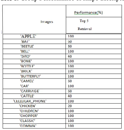
Table 1. Group Performance of shape descriptor
V.
CONCLUSION
The proposed centroid based shape descriptor computes distances for A line using Bresenham algorithm drawn between two opposite pixels on circle forms the bases of computation. Distances between all the edge pixels falling on the above mention line are computing , these distance matrix is nothing but the features extraction for image. Localized histograms are plotted for each bin of an image and the histogram matching is done by bin
wise rotation in a relative way between query image and dataset image. The results obtained are efficient as the features are compact with reduced computations and the descriptor exhibits invariance towards geometrical transformations and mirroring as well due to the normalization process
VI.
REFERENCES
[1].Sonya Eini and Abdulah, Shape retrieval using Smallest Rectangle Centroid Distance, IJSP, Image Processing and Pattern Recognition Vol.6, No.4, August, 2013. [2].Yong Hu, Zuoyon Li, an Improved Shape
Signature for Shape Representation and Image Retrieval, Journal of Software, Vol.8, No.11, November 2013.
[3].Zhiyan Li, Junjie, Heng, Geometry-based 2D Shape Descriptor Retrieval in Large Databse, ICSP 2012.
[4].Bhargavi Mokashi, Dr. Jagadessh Pujari, Prof. Jaya Karur, Implementation of Shape Descriptor Based on DistanceInterior Ratio for Image Retrieval, IJRASET 2015.