R E S E A R C H
Open Access
A generalized design framework for IIR digital
multiple notch filters
Qiusheng Wang
1*and Deepa Kundur
2Abstract
Digital multiple notch filters are used in a variety of applications to remove or suppress multiple sinusoidal or narrow-band interference in digital signals. In this paper, we propose an all-pass filter-based design framework for infinite impulse response (IIR) multiple notch filters. Our approach aims to overcome the limitations of former techniques through greater design capacity and performance. The proposed framework has versatility and enables the tailored use of design constraints thus providing a family of possible multiple notch filter design methods. The design performance and practicality of the proposed framework are verified empirically by a series of experimental results and different applications.
Keywords: Multiple notch filter; Digital notch filter; Digital all-pass filter; Infinite impulse response; Digital filter design; Filter design framework; Weighted least square; Digital signal processing
1 Introduction
Digital notch filters are used to eliminate sinusoidal or narrow-band interference in digital signals while preserv-ing the other frequency components intact [1-4]. They have been widely applied in a variety of disciplines rang-ing from audio signal processrang-ing to biomedical engineer-ing [5-19]. Recently, there has been interest in design-ing multiple-frequency notch filters that aim to suppress two or more frequencies of an input signal [20-25]. Two types, finite-impulse response (FIR) and infinite-impulse response (IIR), exist. As typical, the former exhibits advantages of linear phase and stability while the latter has advantages of narrower stop-band and higher quality fac-tor for the same filter order of more significance to notch filter design [26-34].
Several approaches exist to design IIR multiple notch filters [1-3,21-23,35-40]. Thecascading methodis a pop-ular direct design technique that realizes a multiple notch filter by cascading several well-designed second-order IIR single-notch filters [36]. The resulting system is characterized by a canonical structure for software and hardware realization. The main drawback is that it is restricted to few notch frequencies and very narrow
*Correspondence: [email protected]
1School of Automation Science and Electrical Engineering, Beihang University, Xueyuan Road No.37, Haidian District, 100191 Beijing, China
Full list of author information is available at the end of the article
bandwidths otherwise leading to non-unity pass-band gains [37].
Theoptimal design method requires computations for pole placement that results in a better frequency char-acteristic [2,3,37,38], but highly complex search-based or iterative algorithms are required even for a notch filter with two frequencies [2,38]. For a greater number of notch frequencies, a two-stage approach has been proposed to generate a stable optimal multiple notch filter, but the design procedure involves quadratic programming via an iterative scheme [3].
Theall-pass filter-based methodpresented by S-C. Pei and C-C. Tseng transforms the specifications of a mul-tiple notch filter to those of an equivalent all-pass filter. A linear design equation is constructed to determine the all-pass filter coefficients which are used to character-ize the desired multiple notch filters [1,41]. An improved method was proposed to design a notch filter with only two frequencies [42]. One advantage is that all-pass filter-based methods have normalized analytical forms with no iterative calculations.
lead to the following challenges [42]. The symmetric mag-nitude responses are too prohibitive for applications. The information of the all-pass filter is not fully utilized. And, the linear equation is potentially ill-conditioned due to tangent operations.
Thus in this work, we present a generalized design framework for IIR multiple notch filters whereby we aim to: a) deduce an improved design process of the all-pass filter-based method, b) maximize the availability of phase information of all-pass filter, and c) introduce selection mechanisms and weighting strategies to enable the unified representation of a family of all-pass filter-based methods. We also apply the framework to typi-cal multiple notch filter applications to empiritypi-cally test performance.
In the next section, an improved all-pass filter-based approach is explored for multiple notch filters. Section 3 proposes a generalized framework with selection mech-anisms and weighting strategies. Section 4 verifies the effectiveness and practicality of our framework through experimental results. Final conclusions are drawn in Section 5.
2 Improved multiple notch filter design
Supposes[n] is a desired information-bearing signal cor-rupted by N sinusoidal interference components whose frequencies areωN1,ωN2,· · ·,ωNN. The overall corrupted
signal can be expressed as [1,2]:
x[n]=s[n]+
N
i=1
Aisin(ωNin+φi) (1)
whereAiandφirepresent the magnitude and initial phase
of theith sinusoidal component.
In order to extracts[n] fromx[n] with limited distor-tion, the design specification of an ideal digital multiple notch filter is given by [2]:
Hd(ejω)=
bandwidths can not be realized [22]. Hence, the frequency response of an actual notch filter is the approximation to that of the ideal one.
2.1 All-pass filter-based design process
In this section, we reformulate the all-pass filter-based design process of multiple notch filters. Suppose that the notch frequenciesωN1,ωN2,· · ·,ωNN correspond to
notch bandwidths BN1,BN2,· · ·,BNN, respectively. The
system function of the notch filter is expressed as follows [1,3]:
H(z)= 1+A(z)
2 (3)
whereA(z)is an 2N-order all-pass filter.
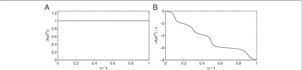
The frequency response of the notch filter is given by: H(ejω)=H(z)z=ejω = 1+A order all-pass filter (N = 4), its magnitude and phase responses are shown in Figure 1. Thus, Aejω can be uniquely characterized byθA(ω):
A(ejω)=ejθA(ω). (5)
Therefore, θA(ω) must be carefully selected such that
Hejωfulfills the design specifications (notch frequencies and bandwidths) of the notch filter.
Generally, a 2N-order all-pass filter is expressed as:
A(z)= a2N+a2N−1z
the numerator and denominator polynomials [1,3]. Given the formulation in Equation 4, determining appropriate values of a1,a2,· · ·,a2N represents the core problem of
all-pass filter-based multiple notch filter design.
To determine a1,a2,· · ·,a2N, we relate them to the
multiple notch filter design specifications as follows. Rear-ranging Equation 6 gives:
Next, substitutingz = ejωand Equation 5 into the left-hand side of Equation 7 gives:
ej[θA(ω)+2Nω]=cos[θ
A(ω)+2Nω]+jsin[θA(ω)+2Nω] .
(8) Correspondingly, the right-hand of Equation 7 becomes:
Figure 1Frequency responses of an 8-order (N=4) all-pass filter.(A)Amplitude response.BPhase response.
From Equations 7, 8, and 9:
cos[θA(ω)+2Nω]+jsin[θA(ω)+2Nω]
Therefore, Equation 10 can also be expressed as:
cos[θA(ω)+2Nω]· Then, we obtain Equation 12 from Equation 11:
2N
By equating the real and imaginary parts of Equation 12 and applying triangular identities: cos(α − β) = cosαcosβ +sinαsinβ and sin(α−β) = sinαcosβ−
Finally, adding both sides of Equations 13 and 14 together gives:
to solve 2Nunknowns.
Suppose M-pairs (ω,θA(ω)) denoted {(ωm,θA(ωm))|
m=1, 2,· · ·,M}are known. Then, a linear equation con-tainingMidentities with 2Nvariablesa1,a2,· · ·,a2Ncan
be constructed from Equation 15 and represented by:
Based on the above discussion, our proposed design process works as follows. Given the N notch frequen-cies ωN1,ωN2,· · ·,ωNN and corresponding bandwidths
specifications BN1,BN2,· · ·,BNN for the multiple notch
filter:
1. Choose the related all-pass filter design constraints {(ωm,θA(ωm))|m=1,2,···,M}to construct Equation 16
whereM≥2N.
2. Solve the linear equations of Equation 16 to obtain the all-pass filter coefficient vector
a=[a1,a2,· · ·,a2N]T.
3. Substitutea1,a2,· · ·,a2Ninto Equation 6 and then
Equation 3 to obtain the multiple notch filter system functionH(z).
We assert that step 1 will have a significant impact on the quality of the multiple notch filter design. Thus, in the next section, we assess four strategies to select design constraints that we verify and compare empirically in Section 4.
2.2 Constraint selections of notch filter design
For a 2N-order all-pass filter, its phase responseθA(ω)is
monotonically decreasing from 0 to−2Nπ as illustrated in Figure 1. Given the continuity of both ω andθA(ω),
there are an uncountably infinite number of (ω,θ(ω)) pairs that can be selected for notch filter design by Equation 16. However, if we restrict ourselves to those quantities related to the design specifications of the mul-tiple notch filter, we can naturally arrive at 3N pairs that may be used. Specifically, those pairs related to the notch frequencies and left-hand and right-hand 3 dB cut-off frequencies employed [1].
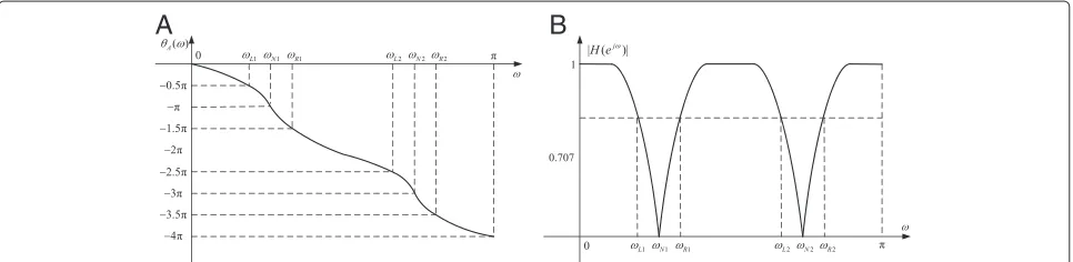
Figure 2 illustrates the relationship betweenθA(ω)and |Hejω| to ensure that Equation 4 results in a suitable
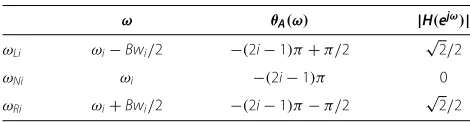
notch filter frequency response that we detail as follows: 1. At notch frequencies,θA(ω)must be equal to an odd
multiple ofπto ensure that|Hejω| =0. Specifically, we require that
θA(ωNi)= −(2i−1)π,(i=1, 2,· · ·,N), to give
AejωNi=ejθA(ωNi)= −1resulting in |HejωNi| =0. Therefore,{(ω
Ni,θA(ωNi))|i=1,2,···,N}
gives|H(ejωNi)| =0at theNnotch frequencies providing a valuable set of filter design constraints. 2. Next, at the left-hand 3 dB frequencies,θA(ω)must
appropriately ensure that|Hejω| =√2/2. One way to achieve this is to let
θA(ωLi)= −(2i−1)π+π/2,(i=1, 2,· · ·,N)such
thatAejωLi=ejθA(ωLi)= −jresulting in |HejωLi| =√2/2. Thus,
{(ωLi,θA(ωLi))|i=1, 2,· · ·,N}gives
|HejωLi| =√2/2providing another valuable set of filter design constraints.
3. Similarly, the right-hand 3 dB frequencies with θA(ωRi)= −(2i−1)π−π/2,(i=1, 2,· · ·,N)give
AejωRi=ejθA(ωRi)=jresulting in |HejωRi| =√2/2providing
{(ωRi,θA(ωRi))|i=1, 2,· · ·,N}as the third set of
filter design constraints.
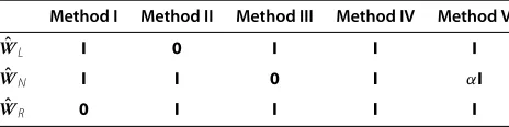
Those relations are summarized in Table 1. It provides 3Npossible(ω,θA(ω))pairs for notch filter design.
How-ever, given that only 2Nare needed to solve Equation 16, four intuitive and effective selection methods from the 3N-pair parameters are possible as highlighted in Table 2. The reader should note that each selection method from Table 2 provides sufficient information to solve Equation 16 sinceM≥ 2N, but they may lead to slightly different results for the same design specifications. We evaluate their design performance in Section 4 but char-acterize each approach briefly below.
Method I utilizes notch and left-hand cutoff frequen-cies as filter design constraints, which is suitable for the case of very narrow interference bandwidths and symmet-rical magnitude responses about the notch frequencies. Method I is adopted in [1].
Method II, in contrast to method I, utilizes notch and right-hand cutoff frequencies for filter design. Roughly, it has the same applicability and limitations as method I, but
Table 1 Relationships amongω,θA(ω), and|H(ejω)|, for
the results of method II are slightly different from those of method I.
Method IIIemploys left-hand and right-hand cutoff fre-quencies as the constraints for filter design. Although it is not limited to very narrow notch bandwidths and symmetrical magnitude responses, it may result in notch frequencies drifting from their desired positions.
Method IVmakes use of all available information: notch frequencies and both left-hand and right-hand cutoff fre-quencies. Thus, it is able to realize a trade-off between notch bandwidths and notch positions effectively enhanc-ing the design performance. The constraint selection method is also adopted by method V in Section 3.
The reader should note thatM= 2N in methods I, II, and III produce unique solutions. In contrast to method IV,M=3Nresults in an over-determined equation with a least-square solution. However, we aim to unify both into a generalized design framework that we present next. 3 Multiple notch filter design framework 3.1 Matrix representations of selection methods
The options for constraints of multiple notch filter design discussed in Section 2.2 can be described col-lectively via vector-matrix forms. LetN notch frequen-cies, N left-hand and N right-hand cutoff frequen-cies be denoted as ωN = [ωN1,ωN2,· · ·,ωNN]T, ωL = [ωL1,ωL2,· · ·,ωLN]T, andωR = [ωR1,ωR2,· · ·, ωRN]T, respectively. We also denote theN×Nzero matrix
with0and theN×Nidentity matrix withI. The selected frequencies can be expressed as:
⎡
Table 2 Parameter constraint selection methods for Equation 16, fori=1, 2,· · ·,N
Method I Method II Method III Method IV
(ωLi,θA(ωLi)) • • •
(ωNi,θA(ωNi)) • • •
(ωRi,θA(ωRi)) • • •
Value ofM 2N 2N 2N 3N
SL,SN, andSRareN×Nsub-matrices equal to either0
orIsuch thatSmaps the set of all possible frequencies of interestωtoωˆemployed for notch filter design.
From Table 2, it is clear that at least two sub-matrices of Smust be set asI. For example, forSL=SN =IandSR= 0,ωLˆ = ωL,ωNˆ = ωN, andωRˆ = 0, which corresponds to method I that only makes use of notch and left-hand cut-off frequencies. Table 3 relates the specific sub-matrix values to all selection methods discussed in Section 2.2.
For convenience, we abbreviate all-pass phasesθA(ωLi),
θA(ωNi), andθA(ωRi)asθLi,θNi, andθRi, respectively, for
i = 1, 2,· · ·,N. Similarly, we defineN×1 vectorsθL =
[θL1,θL2,· · ·,θLN]T, θN = [θN1,θN2,· · ·,θNN]T, and θR = [θR1,θR2,· · ·,θRN]T which correspond toωL,ωN,
andωR, respectively. A similar vector-matrix form related to all-pass filter phases is expressed as follows:
⎡
the same meaning as in Equation 19.
Therefore, four selection methods of (ω,θA(ω)) in
Table 2 can be uniformly represented via Equations 19 and 20 whereby the value ofSdetermines the particular method used for multiple notch filter design.
3.2 Linear equation and least-square solution
If all elements of the selected frequency vector ωˆ and all-pass phase vectorθˆare substituted into Equations 17 and 18, we obtain the following linear equation from Equation 16:
Table 3 Relationships between parameter constraint methods and selection matrix S
Method I Method II Method III Method IV
SL I 0 I I
SN I I 0 I
In general, Equation 21 is an over-determined linear equation that can be solved by the least-square tech-nique [44]: In particular, for methods I, II, and III, Equation 21 degenerates into ordinary linear equations. For example, in method I, SR = 0 implies ωRˆ = 0 and θˆR = 0,
and hence pˆR = 0 andQˆR = 0in Equation 21. Thus, Equation 21 is simplified to:
solution of Equation 23 is as follows:
a=Qˆ−I1pˆI (24)
whereQˆ−I1is the inverse ofQˆI. Similar forms and results as Equations 23 and 24 can be easily surmised for methods II and III.
Generally speaking, for methods I, II, and III,pˆandQˆ of Equations 21 degenerate to a 2N×1 vector and a 2N×2N nonsingularmatrix, respectively. Because the rank of the resulting matrixQˆ is 2N, Equation 21 has a unique solu-tion. In contrast, for method IV, pˆ is a 3N × 1 vector and Qˆ a 3N ×2N matrix whose rank is also 2N; thus, Equation 21 only has a least-square solution due to the structure and rank ofQˆ. Thus, Equation 21 is a general-ized form applicable to the various constraints discussed in Section 2.2.
3.3 Weighted design equation and its solution
For certain applications, the design precision require-ments of notch frequencies are more rigorous than those at the cutoffs and vice versa. For example, in a contam-inated electrocardiogram (ECG) signal, the interference resulting from fundamental and harmonic components of power lines have near-fixed frequency values [7,14,17]. Hence, the design precision requirement for the notch fre-quency values of the filter is stricter than those of the cut-off frequencies. The same is true of rejecting narrow-band interference from amplitude-modulated (AM) broadcasts in corona current of high-voltage direct current (HVDC) transmission lines.
However, until now, both sets of constraints have been treated equally in multiple notch filter design. To address this issue, we propose the introduction of a weighting matrix: sion of Equation 21 is therefore expressed by:
WQaˆ =Wpˆ (26) with the least squares solution given by:
a= The weighting matrices employed in methods I to IV are listed in Table 4. As evident, it is possible to weight the notch and cutoff frequencies with equal or different relative significance.
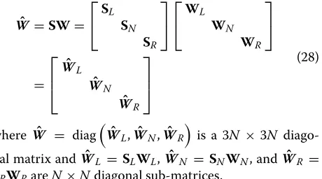
To incorporate such representations to develop new design methods, we combine Sand W to create a new weighting matrixWˆ as follows:
ˆ
We highlight that Wˆ combines the selection matrix S and weighting matrixW together to implement their respective functions jointly. Therefore, an enhanced ver-sion of Equation 26 can be expressed as:
ˆ
WQaˆ =Wˆ pˆ (29) whereais solved as:
a= The readers should note that Equation 29 provides a generalized formulation of the all-pass filter-based mul-tiple notch filter design approach whereby the weighting matrix Wˆ incorporates both the selection mechanisms and weighting strategies. We note that for methods I to IV, the commonIand0sub-matrix structure of bothS andW(as evident in Tables 3 and 4), results in weighting
Table 4 Relationships between design methods and weighting matrix W
Method I Method II Method III Method IV
WL I 0 I I
WN I I 0 I
matrices that have the same form (see columns 1 to 4 of Table 5), despite their different objectives.
Thus, the incorporation of new design constraints can be easily achieved by modifying the weighting matrix of Equation 28. Method V in Table 5 is a new design method derived from Equation 29. It utilizes the same frequency selection method as method IV in Table 2. However, it treats notch and cutoff frequencies with dif-ferent significance through the difdif-ferent weighting matrix. The advantages of method V is demonstrated in Section 4. The readers should note that Table 5 only provides five special cases of weighting matrixWˆ . They can easily be modified to address different design requirements beyond those presented.
3.4 Generalized design framework
Our all-pass filter-based approach to multiple notch filter design can therefore be summarized as follows.
Step 1 Acquire the design specifications of the multiple notch filter as a set ofN notch frequencies andNnotch bandwidths that form a set of 3N constraint frequencies presented in Table 1.
Step 2 For the 3Nfrequencies in step 1, we can determine the 3Nrelated all-pass filter phases from Table 1 and then produce 3N×1 vectorsωandθ.
Step 3 Select one of the constraint methods from Table 2 and determine its corresponding selection matrixSfrom Table 3. From this, compute the frequency vector ωˆ via Equation 19 and the all-pass phase vector θˆ from Equation 20.
Step 4 Substitute all entries ofωˆ andθˆinto Equations 17 and 18 to compute the 3N×1 vectorpˆand 3N×2Nmatrix
ˆ
Q, necessary in step 6.
Step 5 Employing a measure of importance of notch, left-hand and right-left-hand cutoff frequencies determine a suit-able 3N×3Nweighing matrixWfrom Table 4 and then combine it withSto formWˆ using Equation 28.
Step 6 Construct the weighted equationsWˆ Qaˆ = Wˆpˆ and solve it by the least-squares technique of Equation 30. The solutiona=[a1,a2,· · ·,a2N]Tis the desired all-pass
filter coefficient vector.
Step 7 Substitute all entries ofainto Equation 6 to gain system function A(z) of the all-pass filter. Then, substi-tuteA(z)intoH(z) = (1+A(z))/2 to obtain the system functionH(z)of the desired multiple notch filter.
Table 5 Relationships between design methods and weighting matrixWˆ , forα >1
Method I Method II Method III Method IV Method V ˆ to verify whether the design requirements are satisfied. If it is not, go to step 3 to choose a different method and/or step 6 to set a new weighting matrix and repeat the above design process.
Once the desired notch filterH(z)is obtained, it can also be expressed as: notch filter, respectively. Equation 32 is applied to perform notch filtering by iterative operations in time domain. 4 Experiments and results analysis
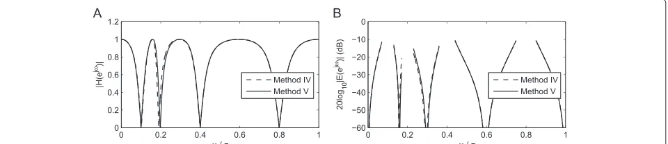
To assess the performance of the proposed framework for multiple notch filter design, the five methods of Table 5 are applied and compared empirically in terms of the pass-band errormetric defined as:
Eejω=20 log10|Hejω−Hd
4.1 Design performance among five methods
Under the conditions of sufficiently narrow bandwidths, the five methods derived from the proposed framework obtain similar results. However, under the rigid conditions of non-uniform notch frequencies and wide bandwidths, the limitations of those methods emerge. For example, for the specifications of ωN = [ 0.1π, 0.2π, 0.4π, 0.8π]T andBW = [ 0.06π, 0.06π, 0.08π, 0.10π]T, the magnitude
responses and pass-band errors of the designed notch filters are presented from Figures 3,4,5 and 6. For con-venience, method V is set as the referenced method (for α=5 in Table 5).
Figure 3Design performance: method I vs. method V.(A)Magnitude responses.(B)Pass-band errors (dB).
Figure 4Design performance: method II vs. method V.(A)Magnitude responses.(B)Pass-band errors (dB).
Figure 5Design performance: method III vs. method V.(A)Magnitude responses.(B)Pass-band errors (dB).
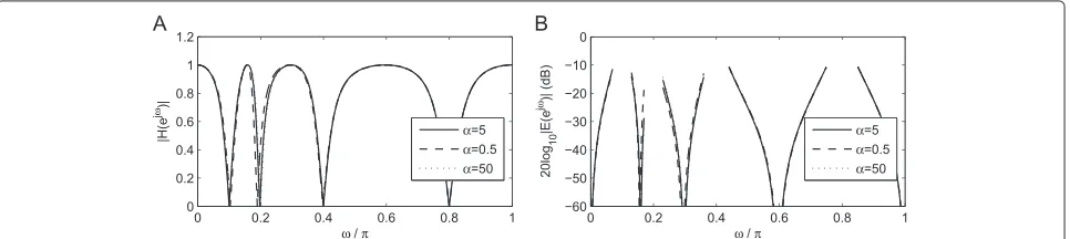
the best performance in our tests and may be the opti-mal choice in practice. Thus, we employ method V for the remainder of experiments. Figure 7 shows that the values ofαin Table 5 affect the design performance of method V. A smallerαcan result in notch frequency shifting, and larger values may decrease the performance at cutoff fre-quencies, although the latter impact is small. Based on the authors’ experience,α should typically be greater than 3 to obtain good performance in practice.
4.2 Comparisons with the classical methods
For the same specifications as Section 4.1, the multiple notch filters are designed by the cascading method, the optimal pole placement method, and the all-pass filter-based method in [1]. Their magnitude responses and pass-band errors of the designed results are shown in Figures 8,9 and 10.
Figure 8 shows that the cascading method cannot meet the design requirements due to its uncontrollable gain. Figure 9 demonstrates that the optimal pole placement method and method V have similar magnitude responses, but the latter does not require iterative calculations. Figure 10 shows that the designed result of the method in [1] is the same as that of method I because they adopt the same all-pass filter phase information to design notch filter, but method I uses the degenerated design forms (shown in Equation 23) with no tangent computations. Therefore, method V has some advantages over those classical methods.
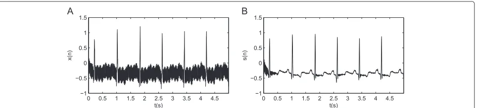
4.3 Interference elimination of ECG signals
The original waveform of a contaminated ECG signal is shown in Figure 11. It is sampled with frequency of 720 Hz. The main interference arises from the fundamental and harmonic components of power lines. To eliminate those interference, a multiple notch filter is designed with specifications ofωN =[ 0.2778π, 0.5556π, 0.8333π]Tand BW = [ 0.01π, 0.01π, 0.01π]T. The frequency responses
of the filter are shown in Figure 12 which demonstrates that the power line interference has been effectively elim-inated by the designed notch filter.
It is worth noting that several oscillations occur near to the origin in Figure 11. This is due to edge effects (due to the iterative operations using Equation 32) at the beginning of the processing window and vanishes quickly.
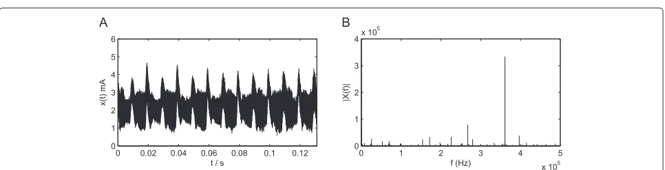
4.4 Radio noise suppression of corona current
Corona current is usually measured to estimate the corona discharge loss of high-voltage direct current (HVDC) power transmission lines. It occupies a wide frequency range and is affected by various electronic and non-electronic factors, especially narrow-band radio noise from civilian broadcasts. The original corona current was measured from the HVDC transmission lines with sam-pling frequency of 1 MHz. Its waveform and spectrum are shown in Figure 13.
Due to the carriers of amplitude modulation (AM) broadcast signals, there are five significantly narrow-band radio noise components in Figure 13. To analyze corona loss accurately, those components must be effec-tively suppressed. The desired notch filter is designed with
ωN = [ 0.3440π, 0.4520π, 0.5348π,0.7220π, 0.7940π]T, and BW = [ 0.008π, 0.008π, 0.008π, 0.008π, 0.008π]T.
The frequency responses of the notch filter are shown in Figure 14.
The filtered waveform and spectrum are shown in Figure 15. Compared with Figure 13, the narrowband radio noise components has been suppressed and the waveform quality is enhanced significantly, although it also has many other interference components due to the complexity of corona discharges. Subsequent calculations show that the signal-to-noise ratio (SNR) of corona cur-rent increases 11.45 dB by the designed notch filter.
Based on the results above, we surmise the following: 1) irrespective of computational complexity and for the same specifications, method V obtains the best results among the derived approaches (methods I to V). 2) Method V outperforms the cascading method and the technique of [1] that exhibits the same results as method I. More-over, method V has close results to the optimal pole placement technique but exhibits lower computational complexity. 3) The effectiveness and practicality of the
Figure 8Performance comparison: cascading method vs. method V.(A)Magnitude responses.(B)Pass-band errors (dB).
Figure 9Performance comparison: optimal method vs. method V.(A)Magnitude responses.(B)Pass-band errors (dB).
Figure 10Performance comparison: method in [1] vs. method V.(A)Magnitude responses.(B)Pass-band errors (dB).
Figure 12The frequency response of multiple notch filter for ECG signal.(A)Magnitude responses.(B)Phase response.
Figure 13The waveform and spectrum of the original corona current.(A)Original waveform.(B)Original spectrum.
Figure 14The frequency response of multiple notch filter for corona current.(A)Magnitude response.(B)Phase response.
proposed framework has been demonstrated by the exper-imental results on power line interference elimination of ECG signals and narrow-band radio noise suppression of HVDC corona currents.
4.5 Discussions
For a multiple digital filter withN notch frequencies, it has 3N constraints (N notch frequencies, N left-hand, andNright-hand cutoff frequencies). All-pass filter-based design methods attempt to find 2N appropriate coeffi-cients to construct a 2N-order rational system function to approximate 3Nconstraints. The proposed framework enables a unified representation of the all-pass filter-based design methods using part or all (2Nor 3N) constraints to find those 2Ncoefficients.
Among the derived methods from the proposed frame-work, methods I, II, and III only use 2N available phase information of all-pass filter. Their design equations are the special forms of the weighted design techniques. They are full rank and have exact solutions. Moreover, for the same design specifications, method I obtains the same results as the method in [1], but it avoids tangent computations which may result in ill-conditioned linear equations.
Methods IV and V utilize all 3N available phase infor-mation of all-pass filter. Their design equations are over-determined and only have least-square solutions. Method V achieves a better compromise between notch frequen-cies and cutoff frequenfrequen-cies. It obtains the best results among the derived methods, although it has very slight frequency drift which can be neglected in practice. The reader should note that in Section 3.2, the 2N notch fil-ter coefficients of methods I, II, and III are directly solved from 2N×2Nregular linear equations via Gaussian elim-ination, but those of methods IV and V are solved from 3N×2Nover-determined linear equations using weighted least-square techniques. Hence, the computational com-plexity of methods IV and V are almost identical but higher than for methods I, II, and III.
In our design framework, the selection mechanisms provide the flexibility to choose a desired design method. The weighting strategies implement the compromise among the restricted conditions. Through the incorpora-tion of diagonal selecincorpora-tion matrixSand weighting matrix W, the improved diagonal matrixWˆ can implement selec-tion and weighting simultaneously, but the calculaselec-tion burden does not increase significantly. The computational efficiency of the proposed framework is far higher than that of the iteration-based design method.
5 Conclusions
In this paper, we present an all-pass filter-based design framework for digital multiple notch filters. The main contributions include: 1) the all-pass filter-based design
process is reformulated as a novel linear equation which overcome the limits of classical design methods due to no tangent operations. 2) All-pass phase selection mecha-nisms and weighting strategies are introduced and incor-porated to meet the diverse of requirements. They con-stitute the main parts of the presented framework under weighted least-square sense. Our framework enables the unified representation of a family of all-pass filter-based design methods. We highlight five design methods (meth-ods I to V) derived from the presented framework. Their performance and effectiveness are compared and vali-dated by a series of experimental results. Our inves-tigations leads us to believe that method V has the best design performance and is recommended for use in practice.
Future work will extend our formation to: a) explore an adaptive IIR multiple notch filter design methodology and b) explore a FIR multiple notch filter by linear phase control mechanisms and weighting strategies.
Competing interests
The authors declare that they have no competing interests.
Authors’ contributions
The core idea was initially developed by QW who carried out related experiments and analysis. Through joint discussion, DK helped to improve the research results, analysis, and presentation. The paper was written and modified jointly by both authors. Both authors read and approved the final manuscript.
Acknowledgements
The authors would like to thank all the reviews for their helpful comments. The first author would like to thank the National Natural Science Foundation (60504023, 61273165) of China for funding this research.
Author details
1School of Automation Science and Electrical Engineering, Beihang University,
Xueyuan Road No.37, Haidian District, 100191 Beijing, China.2Edward S.
Rogers Sr. Department of Electrical & Computer Engineering, University of Toronto, 10 King’s College Road, M5S 3G4 Toronto Canada.
Received: 15 August 2014 Accepted: 25 February 2015
References
1. SC Pei, CC Tseng, IIR multiple notch filter design based on allpass filter. IEEE Trans. Circuits Syst. II: Analog Digital Signal Process.44(2), 133–136 (1997) 2. S Phongsuwan, T Sitthiwongwanich, A Thamrongmas, C
Charoenlarpnopparut, inProc 2011, 8th International Conference on Electrical Engineering / Electronics, Computer, Telecommunications and Information Technology (ECTI-CON). Multiple IIR notch filter design and optimization by Secant approximation (IEEE Piscataway, 2011), pp. 971–974
3. CC Tseng, SC Pei, Stable IIR notch filter design with optimal pole placement. IEEE Trans. Signal Process.49(11), 2673–2681 (2001) 4. A Nehorai, A minimal parameter adaptive notch filter with constrained
poles and zeros. IEEE Trans. on Acoust. Speech Signal Process.
33(4), 983–996 (1985)
5. L Tan, J Jiang, Novel adaptive IIR filter for frequency estimation and tracking. IEEE Signal Process. Mag.186(10), 186–189 (2009)
6. SMM Martens, M Mischi, SG Oei, JWM Bergmans, An improved adaptive power line interference canceler for electrocardiography. IEEE Trans. Biomed. Eng.53(11), 709–717 (2006)
8. DS Leeds, inProceedings of IEEE International Conference on Acoustics, Speech, and Signal Processing (ICASSP). Adaptive noise cancellation of coupled transmitter burst noise in speech signals for wireless handsets (IEEE Piscataway, 2002), pp. IV-3924–3927
9. S Narieda, inProceedings of IEEE International Conference on Vehicular Technology Conference. Downsampling techniques using notch filter for interference cancellation in narrowband wireless systems (IEEE Piscataway, 2011), pp. 1–5
10. H Wei, Z Yan, D Yuandan, Z Jianyi, Z Xiaowei, Z Kuai, Y Cheng, J. Chen, in IEEE International Workshop on Antenna Technology. UWB antenna with multiple frequency notched bands for onboard communications (IEEE Piscataway, 2009), pp. 1–4
11. M Malekpour, M Farshadnia, M Mojiri, inProceedings of 5th International Conference on Power Engineering and Optimization Conference (PEOCO). Monitoring and measurement of power quality indices using an adaptive notch filter (IEEE Piscataway, 2011), pp. 291–296
12. TM Adami, R Sabala, JJ Zhu, inProceedings of International Conference on the 22nd Digital Avionics Systems (DASC’03). Time-varying notch filters for control of flexible structures and vehicles, vol. 12 (IEEE Piscataway, 2003), pp. 7.C.2–7.1-6
13. M Ferdjallah, RE Barr, Adaptive digital notch filter design on the unit for the removal of powerline noise from biomedical signals. IEEE Trans. Biomed. Eng.41(6), 529–536 (1994)
14. O Ozkaraca, AH Isik, NF Guler, inProceedings of 2011 International Symposium on Innovations in Intelligent Systems and Applications (INISTA). Detection, real time processing and monitoring of ECG signal with a wearable system (IEEE Piscataway, 2011), pp. 424–427
15. B Widrow, JR Glover, JM McCool, J Kaunitz, CS Williams, RH Hearn, JR Zeidler, D Eugene, RC Goodlin, Adaptive noise canceling: principles and applications. Proc. IEEE.63(12), 1692–1716 (1975)
16. S Nishimura, A Mvuma, T Hinamoto, inProceeding of 2013 IEEE International Symposium on Circuits and Systems (ISCAS). Tracking properties of complex adaptive notch filter for detection of multiple real sinusoids (IEEE Piscataway, 2013), pp. 2928–2931
17. KJ Kim, JH Ku, IY Kim, SI Kim, SW Nam, inProceedings of International Conference on Control, Automation and Systems (ICCAS ’07). Notch filter design using theα-scaled sampling kernel and its application to power line noise removal from ECG signals (IEEE Piscataway, 2007),
pp. 2415–2418
18. YW Bai, WY Chu, CC Chen, YT Lee, YC Tsai, CH Tsai, inProceedings of 21st IEEE International Conference on Instrumentation and Measurement Technology Conference (IMTC 04). Adjustable 60Hz noise reduction by a notch filter for ECG signals. vol. 3, (All-pass based IIR multiple notch filter design using, 2004), pp. 1706–1711
19. TTC Choy, PM Leung, Real time microprocessor-based 50 Hz notch filter for ECG. J. Biomed. Eng.10(3), 285–288 (1988)
20. TB Airimitoaie, ID Landau, Indirect adaptive attenuation of multiple narrow-band disturbances applied to active vibration control. IEEE Trans. Control Syst. Technol.PP(99), 1–1 (2013)
21. V DeBrunner, S Torres, Multiple fully adaptive notch filter design based on allpass sections. IEEE Trans. Signal Process.48(2), 550–552 (2000) 22. YV Joshi, SC Dutta Roy, Design of IIR multiple notch filters based on
all-pass filters. IEEE Trans. Circuits Syst. II: Analog Digital Signal Process.
46(2), 134–138 (1999)
23. MA Soderstrand, TG Johnson, RH Strandberg, HH Loomis, KV Rangarao, Suppression of multiple narrow-band interference using real-time adaptive notch filters. IEEE Trans. Circuits Syst. II: Analog Digital Signal Process.44(3), 217–225 (1997)
24. FH Su, YQ Tu, HT Zhang, X Hua, TA Shen, inProceedings of 8th World Congress on Intelligent Control and Automation (WCICA). Multiple adaptive notch filters based a time-varying frequency tracking method for Coriolis mass flowmeter (IEEE Piscataway, 2010), pp. 6782–6786
25. QS Wang, HW Yuan, Improved approach for digital multiple notch filter design. Journal of Beijing University of Aeronautics and Astronautics.
37(10), 1250–1255 (2011)
26. P Zahradnik, M. Vlcek, Fast analytical design algorithms for FIR notch filters. IEEE Trans. Circuits Syst. I: Regular Papers.51(3), 608–623 (2004) 27. P Zahradnik, M Vlcek, B Simak, Equiripple FIR triple narrow band filters. 2002 Asia-Pacific Conference on Circuits and Systems, APCCAS ’02 vol. 1, 83–86 (2002)
28. P Zahradnik, M Vlcek, An analytical procedure for critical frequency tuning of FIR filters. IEEE Trans. Circuits yst. II: Express Briefs.53(1), 72–76 (2006) 29. R Deshpande, SB Jain, B Kumar, Design of maximally flat linear phase FIR
notch filter with controlled null width. Signal Process.88(10), 2584–2592 (2008)
30. CC Tseng, SC Pei, Design of an equiripple FIR notch filter using a multiple exchange algorithm. Signal Process.75(3), 225–237 (1999)
31. J Okello, S Arita, Y Itoh, Y Fukui, M. Kobayashi, inProceedings of IEEE International Symposium on Circuits and Systems (ISCAS 2000). An adaptive notch filter for eliminating multiple sinusoids with reduced bias, vol. 3 (IEEE Piscataway, 2000), pp. 551–554
32. MR Petraglia, SK Mitra, J Szczupak, Adaptive sinusoid detection using IIR notch filters and multirate techniques. IEEE Trans. Circuits Syst. II: Analog Digital Signal Process.41(11), 709–717 (1994)
33. PA Regalia, An improved lattice-based adaptive IIR notch filter. IEEE Trans. Signal Process.39(9), 2124–2128 (1991)
34. S Kocon, J. Piskorowski, inProceedings of 17th International Conference on Methods and Models in Automation and Robotics (MMAR). A concept of time-varying FIR notch filter based on IIR filter prototype (IEEE Piscataway, 2012), pp. 91–95
35. G Stan, Nikoli ˇai´c, ´c S, Digital linear phase notch filter design based on IIR all-pass filter application. Digital Signal Process.23, 1065–1069 (2013) 36. PA Regalia, SK Mitra, PP Vaidyanathan, The digital all-pass filter: a versatile
signal processing building block. Proc. IEEE.76(1), 19–37 (1988) 37. S Yimman, S Praesomboon, P Soonthuk, K. Dejhan, inProceedings of
International Symposium on Communications and Information
Technologies, ISCIT ’06. IIR multiple notch filters design with optimum pole position (IEEE Piscataway, 2006), pp. 281–286
38. C Charoenlarpnopparut, P Charoen, A Thamrongmas, S Samurpark, P Boonyanant, inProceedings of 6th International Conference on Electrical Engineering / Electronics, Computer, Telecommunications and Information Technology, ECTI-CON 2009. High-quality factor, double notch, IIR digital filter design using optimal pole re-position technique with controllable passband gains (IEEE Piscataway, 2009), pp. 1163–1166
39. J Piskorowski, Suppressing harmonic powerline interference using multiple-notch filtering methods with improved transient behavior. Measurement.45(6), 1350–1361 (2012)
40. P Srisangngam, P Mongkudvisut, S Yimman, K Dejhan, inInternational Symposium on Intelligent Signal Processing and Communications Systems, ISPACS 2008. Symmetric IIR notch filter design using pole position displacement (IEEE Piscataway, 2008), pp. 1–4
41. SC Pei, CC Tseng, inProceeding of 1996 IEEE Digital Signal Processing Applications TENCON ’96. IIR multiple notch filter design based on allpass filter, vol. 1 (IEEE Piscataway, 1996), pp. 267–272
42. A Thamrongmas, C Charoenlarpnopparut, inProceeding of 7th International Workshop on Multidimensional Systems. All-pass based IIR multiple notch filter design using Gröbner Basis (IEEE Piscataway, 2011), pp. 1–6
43. AV Oppenheim, RW Schafer, JR Buck,Discrete-time signal processing. (Prentice Hall, New Jersey, 2009)