Technology (IJRASET)
Closed Loop Control of DC to DC Converter with
Hybrid Input Sources
Guggulothu Gopala Naik1, D.Sunder Singh2 1
PG Student, 2Assistant Professor, Dept. of EEE, Gudlavalleru Engineering College, Gudlavalleru (A.P)
Abstract: This paper proposes a closed loop based dc-to-dc power conversion circuit for distributed generation systems. With the two-port converter, the load can be powered from two different dc sources, which can be a combination of two from a solar-cell panel, a fuel-cell set, a battery bank, etc. and for continuous supply and reliable output we extended the circuit into closed loop system. The power conversion circuit consists of two active power switches by commonly using an inductor and an output filter capacitor. By adjusting the duty-ratio of the active power switch and gate triggering pulses of the inverter with the closed loop method, the voltage regulation at the output as well as the power coordination between two input sources can be made. The circuit operation is described in detail with the theoretical analysis and computer simulation. An experimental circuit has been built and tested to verify the analyzed and simulated results.
Keywords- two-port dc-to-dc power converter; distributed generation system; power coordination
I. INTRODUCTION
In our daily life, power electronic converters have been widely used, not only for industry applications but also in many electronic products, such as portable devices and consumer electronics. Actually, most electronic devices are not using energy directly from the power system or a battery set. To provide the required voltage or current level to a load, in general, a power electronic converter is interposed between the power source and the load to perform the conversion of the voltage or current level and in addition to regulate the power requirement. A conventional power electronic converter is supplied from a single input source, but may provide multiple outputs. In the case that two or more voltage or current levels are required by the loads, a transformer with multiple output windings is employed [1], [2]. On the other hand, however, for some applications, the loads may not be powered from a single source but from two or more input sources specified by different voltage, current, and power ratings [3-13]. For example, a solar power based street lamp is mainly supplied from solar cells, but needs a subordinate battery power. Such a prerequisite can be found more and more frequently in applications with renewable power generation, especially in a hybrid system with different kinds of power sources. Conventionally, multiple power converters are needed to convert power from manifold power sources. Such a simple solution is obviously of high cost and inefficient. To cope with this prerequisite, this paper proposes a three-port dc-to-dc converter, which is capable of converting power from two inputs sources to the load. The hybrid power sources deliver energy to the load alternatively by switching active power switches on and off, respectively.
II. CIRCUIT CONFIGURATION
A. Open loop
The power conversion circuit of the proposed hybrid input dc-to-dc converter is shown in Fig. 1, which is essentially an integration of a boost converter and a buck-boost converter. The integrated power converter consists of two active power switches, S1 and S2, for boost conversion and buck-boost conversion, respectively, by commonly using a diode, D, an inductor, L, and a filter capacitor, C. The two dc sources, Vin1 and Vin2, are treated as the primary and secondary sources, depending on the capacity and the dependability of the power sources. The primary source has a capability of providing more energy to the load and is more durable than the secondary source is. Two active power switches are turned on and off periodically at a same frequency but are activated alternately in a period. The powers delivered by two sources are coordinated by controlling their duty-ratios.
Technology (IJRASET)
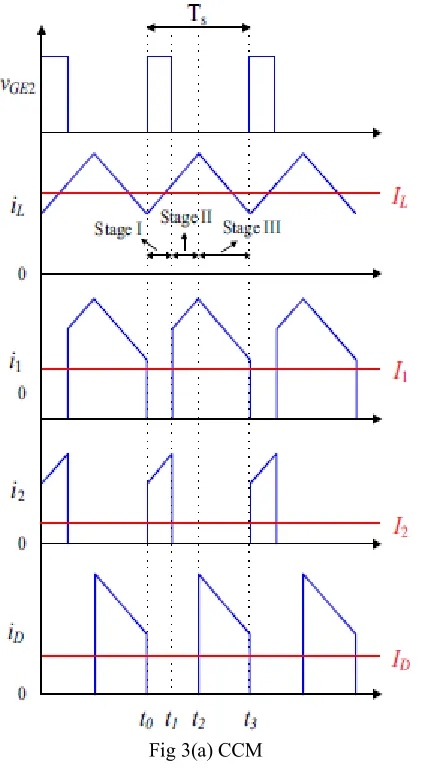
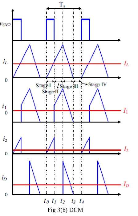
The power conversion circuit can be operated at the continuous conduction mode (CCM) or the discontinuous Conduction mode (DCM), depending on the continuity of the inductor current. In which, the duty-ratios of two active power switches are d1 and d2, respectively. At the CCM, the power conversion circuit is operated through Stages I, II, and III sequentially in a switching period, T2. Stage IV occurs only at the DCM when the inductor current falls down to zero. The steady state operation is described in the followings.
Stage 1:
As the active power switch S2 is turned on, the diode D will be reversely biased and turned off. The inductor is charged by the secondary voltage source, V2, and the inductor current, iL, increases linearly. In this stage, the filter capacitor delivers the stored energy to the load.
Stage 1 circuit Stage 2:
As S2 is turned off, the active power switch, S1 is turned on, and the diode D is now still turned off. The primary dc power source is providing electromotive force for charging the inductor in this stage. At the same time, iL increases linearly after preceding stage.
Stage 2 circuit
The filter capacitor is still providing energy to the load in this stage.
Stage 3:
When the power switch S1 is turned off, the diode D is forced to be turned on to conduct the inductor current. In this stage, the load draws energy from the primary source and the inductor.
Technology (IJRASET)
Stage 4:
[image:4.612.198.430.140.287.2]This stage only happened when the inductor current declines to zero, both S and D are turned off. The filter capacitor supplies a current to the load, and voltage on the capacitor declines.
Fig. 2 depicts the theoretical waveforms on the key components of the power converter for CCM and DCM.
Stage 4 circuit
The output voltage of the power converter is the sum of V1 and the buck-boost conversion output voltage from V1 and V2. This equation indicates the output voltage is always higher than the input voltage. In practice, the sum of d1 and d2 in one cycle is limited to be less than 0.9.
[image:4.612.203.414.335.719.2]Technology (IJRASET)
Fig 3(b) DCM
B. Closed Loop
[image:5.612.95.538.42.438.2]The control strategy for dc-dc converter under both CCM and DCM modes are developed under closed loop control base. In both DCM and CCM modes the pulses for switches are obtained by comparing output voltage with reference value of dc output voltage as per the CCM and DCM values. And also conventional PI controller is used to control the output voltage as shown in figure4.
Fig 4: Closed loop control strategy for DCM and CCM modes
III. EXPERMENTAL RESULTS
[image:5.612.200.424.82.431.2] [image:5.612.210.415.505.621.2]Technology (IJRASET)
the measured current waveforms on the key components when the converter is operated at CCM and DCM, respectively. Primary
input voltage 10V, Secondary input voltage 5 – 30 V, Constant Load current0.3A, Inductance 237uH, Filter
capacitor330uF, IGBT S1 and S2 IXGR35N120B, Diode PSR10C40
[image:6.612.202.410.149.263.2]Case 1: OPEN LOOP
Fig 5: Simulation Circuit for Open Loop Circuit
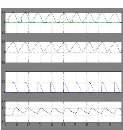
Fig. 6 shows the measured current waveforms on the key components when the converter is operated at CCM and DCM, respectively.
Fig 6(a) Simulation Results for DCM Mode
[image:6.612.189.408.308.455.2] [image:6.612.205.416.467.690.2]Technology (IJRASET)
The converter is operated in CCM mode, in this case V0 and current wave forms are shown in figure 6(a) and figure 6(b) shows the current waveforms for DCM mode. In this the inductor current rises faster than that CCM.
Demerits
1) In this Output is inaccurate.
2) They are unreliable.
3) Any change in output cannot be corrected automatically
[image:7.612.214.447.216.369.2]4) Unfortunately this type of open-loop system is inadequate as variations or disturbances in the system Case 2: CLOSED LOOP
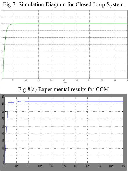
[image:7.612.197.417.384.677.2]Fig 7 shows the simulation result for closed loop diagram for both CCM and DCM modes.
Fig 7: Simulation Diagram for Closed Loop System
Fig 8(a) Experimental results for CCM
Technology (IJRASET)
IV. CONCLUSION
This paper proposed a closed loop controlled three-port dc-to-dc power conversion circuit which can be powered from three input sources. The power coordination between input sources and the voltage regulation can be made by adjusting the duty-ratios of two active power switches and gate pulses of the inverter switches with the help of closed loop. As compared with the conventional open-loop multiple-input power converter, the proposed conversion circuit has less component count and generates a better results. The power conversion circuit can be used in a distributed generation system with different dc power sources.
REFERENCES
[1] Chin-Sien Moo, Tsung-Hsi Wu, Kong-Soon Ng, and Yao-Ching Hsieh “DC-to-DC Converter with Hybrid Input Sources” in 3rd IEEE International Symposium on Power Electronics for Distributed Generation Systems (PEDG) 2012
[2] K. P. Yalamanchili and M. Ferdowsi, “Review of Multiple Input DC-DC Converters for Electric and Hybrid Vehicles,” in Proc. IEEE VPPC Conf., September 2005, pp. 160-163.
[3] Y. M. Chen, Y. C. Liu, and S. H. Lin, "Double-input PWM DC/DC converter for high/low voltage sources," in Telecommunications Energy Conference, 2003. INTELEC '03. The 25th International, 2003, pp. 2732.
[4] D. Liu and H. Li, “A Novel Multiple-Input ZVS Bidirectional DC-DC Converter,” in Proc. IEEE IECON Conf., Nov.r 2005, pp. 579-584.
[5] H. Tao, A. Kotsopoulos, J. L. Duarte, and M. A. M. Hendrix, “Family of Multiport Bidirectional DC–DC Converters,” IEE Proceedings-Electric Power Applications, vol. 153, no. 3, pp. 451-458, May 2006.
[6] N. Vazquez, A. Hernandez, C. Hernandez, E. Rodriguez, R. Orosco, and J. Arau, “A Double Input DC/DC Converter for Photovoltaic/Wind Systems,” in Proc. IEEE PESC Conf., Jun. 2008, pp. 2460-2464.
[7] A. Khaligh, “A Multiple-Input Dc-Dc Positive Buck-Boost Converter Topology,” in Proc. IEEE APEC, Feb. 2008, pp. 1522-1526.
[8] S. H. Choung and A. Kwasinski, “Multiple-Input DC-DC Converter Topologies Comparison,” in Proc. IEEE IECON Conf., Nov. 2008, pp. 2359-2364. [9] K. Gummi and M. Ferdowsi, “Derivation of New Double-Input DC-DC Converters Using H-Bridge Cells as Building Blocks,” in Proc. IEEE IECON Conf., November 2008, pp. 2806-2811.
[10] R. C. Zhao and A. Kwansinski, “Multiple-Input Single Ended Primary Inductor Converter (SEPIC) Converter for Distributed Generation Applications,” in Proc. IEEE ECCE Conf., Sep. 2009, pp. 1847-1854.
[11] W. Qin, Z. Jie, R. Xinbo, and J. Ke, "A double-input flyback DC/DC converter with single primary winding," in Energy Conversion Congress and Exposition (ECCE), 2010 IEEE, 2010, pp. 1938-1944.
[12] F. Sedaghati and E. Babaei, "Double input Z-source DC-DC converter," in Power Electronics, Drive Systems and Technologies Conference (PEDSTC), 2011 2nd, 2011, pp. 581-586.