2017 2nd International Conference on Computer Engineering, Information Science and Internet Technology (CII 2017) ISBN: 978-1-60595-504-9
A Frequency Band Phase Calibration Method Based
on Differential Group Delay
JIE LIU and JINYAO CAI
ABSTRACT
Due to the disadvantages of single calibration way and low efficiency of the dual-channel monopoles radar phase calibration method and single frequency calibration for one time, we propose a method of phase calibration based on the information plus channel group delay, by which we can deduce the phase of the whole frequency just through one single phase calibration with high efficiency. In this paper, we explain the reason for dual-channel monopoles radar, analyze the disadvantages of current calibration method and prove the feasibility of this phase calibration method based on group delay. By experiments, we testify that the calibration results by this method can satisfy the performance demands of the equipment. This method improves the calibration process and efficiency.
KEYWORDS
Phase Calibration, Monopoles, Group Delay.
INTRODUCTION
Most of the T&C radars (telemetry & control radars) use two-channel monopoles tracking system, which has high tracking accuracy, high data rate, long operating range, and strong anti-interference capability. But due to the design principle for this system, one needs to make sure the phase consistency of sum and difference channel to work out the correct angle error. That is normally called phase calibration [1].
The existing calibration methods include tower calibration, synchronous satellite calibration and curve-fitting based calibration [2], etc. All these methods do phase calibration for single point every time, which is less effective. If multi-point phase calibration is needed, it will have huge coordination work load and huge data size, which is not convenient. Meanwhile, along with the increasing needs for emergent telemetry & control at sea, surveying ships always need to execute outburst emergent telemetry & control tasks. All these make higher requirement for the phase calibration technology of ship borne monopoles radar.
To deal with the disadvantage of single point calibration of the current methods, this paper provides a method which calculates out the phase of every point in the whole frequency band through measuring the differential group delay (DGD) of the tracking link sum and difference channel. In this method, phase of all points in the whole frequency band can be got by make phase calibration for single point in the frequency band. It is fast and efficient, and greatly reduced the task preparation procedure. In this paper, the method of making phase calibration through DGD will be _________________________________________
demonstrated in theory and will discuss the practical application value of this method through analyzing and verifying test data.
BRIEF INTRODUCTION OF CURRENT CALIBRATION TECHNOLOGY
Reason for Phase Calibration
Two-channel monopoles tracking system uses single whole multimode feed. It uses TE11 as common mode, high-order mode TE21 as differential mode, and uses the eight uniformly distributed coupling holes on the circular waveguide to get the optimism coupling of high-order mode TE21. Also, using the combination of magic T and network to add azimuth error signal ΔAZ and pitch error signal ΔEL together, Δ=ΔAZ+jΔEL. At the same time could get export which can form left-hand or right-hand circular polarization (or left-right-hand plus right-right-hand circular polarization). After sending sum and difference signals to two-channel monopoles tracking receiver, location and pitch angle error signal could be demodulated.
Below formulas could be got through two-channel monopoles demodulation principle:
( ) sin cos( ) cos sin( ) E
U t K K (1)
( ) cos cos( ) sin sin( )
A
U t K K (2)
Thereunto, θ is any space angle on the direction of off-target antenna electrical foresight. Φ is the included angle of the horizontal plane and the composed plane of foresight line and target point P. ΔΦ is the phase difference of sum and difference channel. [3]
Formula (2-1) means that UE represents angle error voltage in pitching direction. Formula (2-2) means that UA represents angle error voltage in azimuth direction. And K in the formula represents angle error gain. It is observed that when ΔΦ≠0° or ΔΦ≠180°, that is when the phase shifts of sum and difference signal are inconsistency, both UE and UA are composed by two parts, and the second part is the cross-coupled term. Therefore phase calibration is needed to get the phase difference △grit of the sum and difference channel.
Current Calibration Methods
Currently, there are two calibration methods for ship-borne monopoles radar: Tower calibration and synchronous satellite calibration.
Tower calibration means that a surveying ship can calibrate through calibration Tower when it berths at the wharf. The advantage for Tower calibration is that it has a simple principle and method, and it’s easy to operate. The result is correct and reliable. But the disadvantage is that it can only calibrate one frequency point each time. The work load and coordination load are huge.
methods, either tower calibration or synchronous satellite calibration, doesn’t have a good solution for multiple frequency point’s calibration. So, there is an urgent need for a new calibration method for ship-borne monopoles radar to fulfill task needs.
THE PHASE CALIBRATION BASED ON DIFFERENTIAL GROUP DELAY
The Definition of Differential Group Delay
In a transmission system, because of the effect of some inert elements (e.g., Capacitance, inductance, transistor, etc.), the output voltage is posterior to input voltage for some time τ0, that is called filter delay.
If the delay originated by the signal of some angular frequency ωi is τ0, then the phase shift generated is ωiτ0. If all the delays of frequency component are τ0, then the phase shift generated should be:
0
( )
(3)
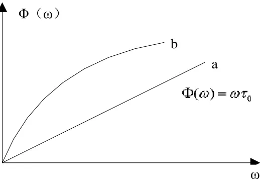
Obviously, phase shift changes along with the change of angular frequency ω. Φ (ω) in it could be put down as the difference of signal input phase and output phase. In ideal conditions, if you draw it in a coordinate, it should be straight line through the origin with a slope of τ0, as the curve an in figure 2, normally the relation curve of Φ (ω) and ω is called phase-frequency curve. But in the real transmission system, the delay to each kind of frequency components in signals are different, that is phase-frequency curve is non-linear, as curve b in figure 2. The delay of all phase-frequency components can be expressed as:
0 ( ) /
(4)
It presents the absolute relation between phase shift and frequency. Sometimes it is called “phase delay”. In a narrow frequency range, the small part of phase characteristic curve can be treated as straight line, and its slop is:
( ) /
(5)
Taking the limit when Δω→0, we can get:
0
1 lim
2
d d f
d df
(6)
Φ
(
ω
)
ω
a
[image:4.612.157.416.80.264.2]b
Figure 1. Phase-frequency curve.
Principle of Measurement
Figure 2 shows that, to a linear system, its Phase-frequency Curve should be the linear function of the relative phase frequency. But to a non-linear system, it can also be treated as linear in a narrow frequency range. The group delay parameter of the specific frequency points can be get by similar procession method as linear system in the adjacent frequency range [5]. To a two-channel monopoles radar, sum and difference channel can be separately treated as a single transmission system, and the phase shifts generated are Φ(f)sum and Φ(f)difference. Then the phase difference of sum and difference route, i.e., the phases need to be calibrated are:
( )= ( )f f - ( )f
sum di f f er ence (7)
If in the whole frequency band, Φ(f) and f have linear relation, as curve a in figure 2, we can get from the definition of group delay that, the differential group delay are the same in the whole frequency band. We can get phases of all frequency points in the whole frequency band if we know one phase of any frequency points.
Figure 2. Link block diagram of the tracking system.
Feed
If a signal with a frequency of moving from down converter output to tracking receiver in the sum route generates a phase shift of:
1 1 0
( )f 2 f 70M* 2
(8)
Among which, τ1 is the delay generated from feed source to down converter output. It is the delay generated from down converter output to tracking receiver. In the same way, we can get the phase shift of difference route is:
'
2 2 0
( )f 2 f 70M* 2
(9)
Sum and difference rout phase difference is:
'
1 2 1 2 0 0
( )f ( )f ( )f 2 (f f ) 70M* 2 ( )
(10)
Test Verification
From formula 3-8 we can get that the phase difference of sum and difference route can be divided into two parts. Among which the signal frequency is fixed as 70MHz transmitting from down converter output to tracking receiver. Meanwhile, transmission route and components passed by are fixed. So τ0-τ’0 is fixed. That means the phase difference of sum and difference route is fixed from down converter output to tracking receiver. So, we can get the phase difference of the whole route by solving
1 2
2 ( f f ).
Make'( )f 2 ( f 1 f2), frequency of getting differential, then:
'
1 2
1 2
d f
df
(11)
Among which, τ is the differential group delay of sum and difference route from feed source to down converter output.
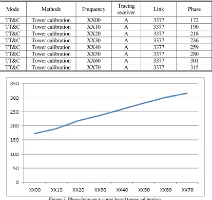
TABLE 1. RESULT OF CALIBRATION.
Mode Methods Frequency Tracing
receiver Link Phase
TT&C Tower calibration XX00 A 3377 172
TT&C Tower calibration XX10 A 3377 190
TT&C Tower calibration XX20 A 3377 218
TT&C Tower calibration XX30 A 3377 236
TT&C Tower calibration XX40 A 3377 259
TT&C Tower calibration XX50 A 3377 280
TT&C Tower calibration XX60 A 3377 301
[image:6.612.92.505.64.453.2]TT&C Tower calibration XX70 A 3377 315
Figure 3. Phase-frequency curve based tower calibration.
Calculating out from phase-frequency curve that:
6
2.15 4558
( ) 2 * *10 2 2 0,1, 2,3...
360 360
f f n n
(12)
' 2.15 6
( ) 2 * *10
360
f f
(13)
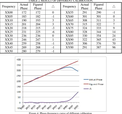
In the range of XX00-XX70, Φ’(f) and f are linear, τ is fixed value, the phase difference generated in this link route can be get from formula (3-11), the phase difference from down converter output to tracking receiver is fixed, the phase difference of the whole sum and difference route can be get by adding them together. To pick a point every 5MHz in the whole working frequency range, get phase value separately by differential group delay calibration and tower calibration, data is as below:
TABLE 2. RESULT OF DIFFERENT CALIBRATION.
Frequency Actual
Phase
Figured
Phase △ Frequency
Actual Phase
Figured
Phase △
XX00 172 172 0 XX55 291 290 -1
XX05 183 182 -1 XX60 301 301 0
XX10 190 193 3 XX65 308 311 3
XX15 201 204 3 XX70 315 322 7
XX20 218 215 -3 XX75 324 333 9
XX25 231 225 -6 XX80 328 344 14
XX30 236 236 0 XX85 330 354 24
XX35 246 247 1 XX90 322 365 43
XX40 259 258 -1 XX95 306 376 70
XX45 269 268 -1 XY00 291 387 96
[image:7.612.90.507.58.447.2]XX50 280 279 -1
Figure 4. Phase-frequency curve of different calibration.
The result shows that, in the range of XX00-XX70, the phase we got from formula calculation is as consistency as from tower calibration. The calibration accuracy is less than 8°, which can fulfill the request of equipment design target; in the range of XX70-XY00, the phase-frequency curves of part of the components are non-linear, therefore this method cannot be used.
APPLICATION PROSPECT
Through the theoretical derivation and data analysis of differential group delay phase calibration, the result shows that, this method works in most part of the working frequency band; due to device performance fails to meet the condition, in small part of the working frequency band, this method cannot be used. But to most of the works for surveying ships to execute, differential group delay phase calibration method can not only be used, but also have an error less than or equal than 8°, which can completely fulfill task requirement.
got the feasibility and super performance of this method. This calibration method is easy to use and convenient. It has great practical application value, and has below innovation points:
1. Apply phase delay to phase calibration area for the first time, which highly improved the working efficiency of multi-frequency-point phase calibration.
2. Achieved the phase calibration of frequency band innovatively, which provides a new calibration method for the follow-up other calibration system.
REFERENCES
1. Jing Li. TE21 mould monopulse auto tracking system of radio communication technology. 2005, 31(6):42-44.
2. Baishi Li, Chongyan Xu, Yunqi Fu, Jingguo Yin. The method of phase calibration based on curve fitting of the monopulse tracking system. Modern Radar, 2010, 32(12):14-19.
3. Liankui Wei. Method of fast calibration of Ship-Borne monopulse tracking radars[J] Journal of Spacecraft TT&C technology, 2013, 32(1):48-52.
4. Deru Li. Group delay measurement technology [M]. Publishing House of Electronics Industry, 1990.